Meaning
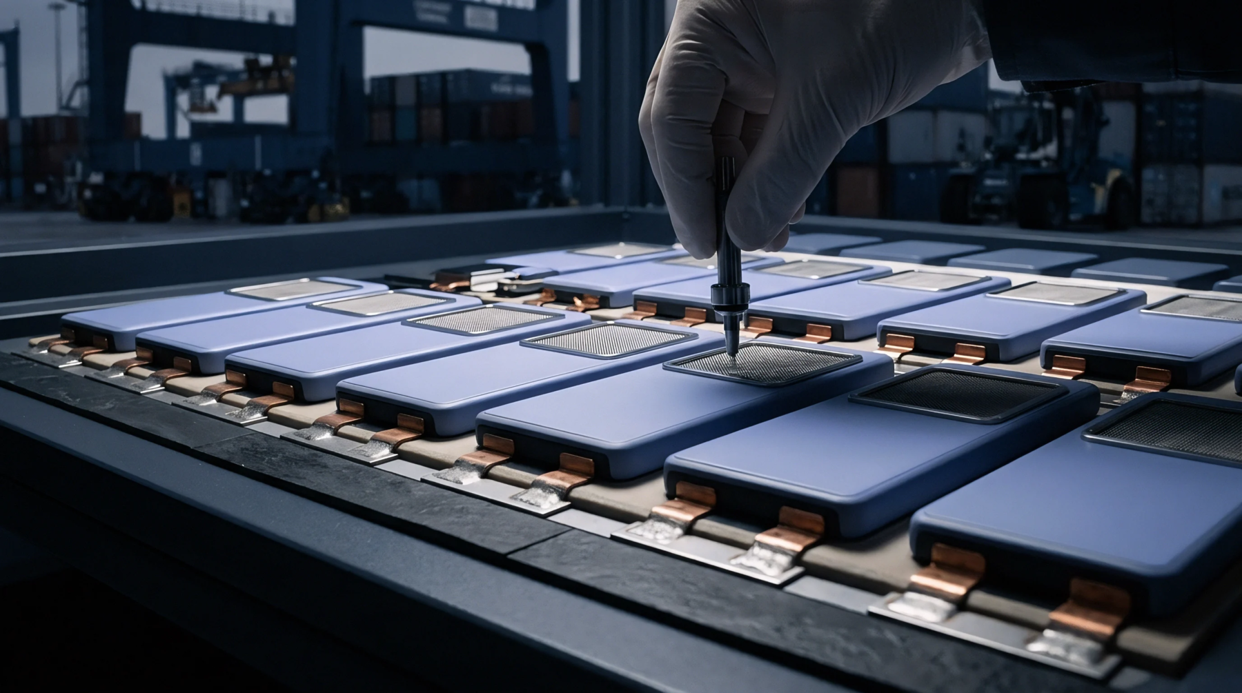
Force applied by external hardware to a lithium-ion cell stack ensures optimal performance during charging and discharge cycles. Mechanical clamping pressure refers to the normalized load maintained across the faces of a battery pack or module to preserve interface contact. Such load minimizes swelling and prevents internal delamination between layers of the separator and electrode.
A device or fixture supplies this load throughout the operational life of the unit. The value stops applying at the boundary where the force compromises the internal structure or causes puncture of the pouch film. Maintaining this pressure prevents capacity loss caused by contact resistance or physical separation between the active materials and the current collectors within the cell.
Load Distribution
Uniformity of contact across the entire surface area of the electrodes affects how ions move during electrochemical reactions. Mechanical clamping pressure provides the resistance necessary to counteract the volumetric expansion of graphite anodes during lithiation. When the fixture provides insufficient load, the internal materials experience micro-delamination that degrades long-term cycle life.
Excess force induces damage to the jelly roll or stacked configuration by distorting the separator pores. Precise control of the torque on bolts or the stiffness of the springs within the assembly keeps the force within the range specified by the cell manufacturer. Engineers calculate this parameter by dividing the total force applied by the total active surface area of the electrode stack.
Maintaining this steady force prevents the formation of hot spots that occur when localized pressure gradients develop across the battery components.
Structural Integration
Thermal management systems often combine with the hardware designed to hold the battery modules in place. Mechanical clamping pressure acts as a baseline requirement for the efficacy of heat dissipation when thermal pads reside between the cell surface and the cooling plate. Compression ensures the thermal interface material fills all air gaps to reach the desired thermal conductivity.
If the assembly lacks adequate force, the resistance to heat transfer spikes and the cells reach temperatures that exceed safety limits. Testing protocols verify this connection by measuring the temperature gradient between the cell skin and the heat sink under fixed load conditions. Manufacturers calibrate the tensioning tools to ensure every module experiences consistent force.
Variations in the tightening of individual bolts result in non-uniform aging across the pack because some cells experience more mechanical stress than others.
Commercial Calibration
Purchasing specifications for energy storage systems include strict tolerances for the force exerted by the enclosure housing. Mechanical clamping pressure dictates the physical dimensions of the pack assembly and determines the compatibility of the module with the vehicle or rack design. Procurement teams request data sheets that define the upper and lower bounds for acceptable load because operating outside these limits voids the warranty and compromises safety certifications.
Vendors provide specific torque requirements for installation to ensure the force reaches the level intended by the design. Laboratory equipment measures this force during the validation of prototype builds to confirm that the mechanical design holds the cells firmly without crushing the internal architecture. High levels of force correlate with lower internal resistance and better power delivery during high current pulses.