Hard Carbon Precursor Selection and Thermal Carbonization Principles
Hard carbon performance relies on precursor heteroatom crosslinking and tuned carbonization thermal ramps to maximize closed porosity and initial capacity.


Origin
Hard carbon synthesis requires non-graphitizing precursors rich in aliphatic crosslinks, heteroatoms, or rigid three-dimensional networks that prevent parallel crystallite alignment during heat treatment. While soft carbons reorder into graphite sheets above 1500 degrees Celsius, hard carbon precursors preserve a disordered, turbostratic framework past 2000 degrees Celsius. Yield drops sharply when the starting chemistry lacks sufficient oxygen or aromatic crosslinks prior to pyrolysis.
This initial feedstock selection sets the working baseline between sloping and plateau capacity in both sodium-ion and lithium-ion anodes.
Raw Material Selection and Carbon Network Formation
Biomass, synthetic resins, and heavy fossil fractions follow markedly different thermal decomposition paths. Bio-derived feedstocks like coconut shells, starch, cellulose, and lignin provide natural abundance alongside high oxygen-to-carbon atomic ratios; intramolecular oxygen forms ether and carbonyl bridges during early degradation, blocking long-range alignment of aromatic sheets. Synthetic thermosets, including phenolic and furfuryl alcohol resins, deliver consistent architectures and high purity.
Phenolic systems crosslink through methylene bridges into rigid frameworks that carbonize into isotropic networks.
Petroleum and coal tar pitches require chemical intervention to avoid graphitizing. Their polycyclic aromatic hydrocarbons stack readily under heat unless interrupted by crosslinking agents or aggressive oxidative stabilization. Introducing oxygen or sulfur into the pitch modifies liquid-phase pyrolysis kinetics, suppressing mesophase sphere growth and locking in structural disorder.

Biopolymer Processing and Resin Crosslinking Mechanisms
Feedstock chemistry governs both carbon yield and final microtexture. Lignin yields more fixed carbon than high-cellulose biomass because its complex phenylpropanoid network is inherently resistant to heat. Cellulose depolymerizes heavily between 300 and 400 degrees Celsius, shedding carbon monoxide, carbon dioxide, and water vapor that carve open, high-surface-area pores if unchecked.
Resins break down along more predictable lines, shedding methyl and hydroxyl groups to leave behind an intact three-dimensional skeleton.
| Precursor Family | Oxygen/Carbon Ratio | Carbon Yield (% w/w) | Ash Content (% w/w) | Optimal Heat Temp (°C) | ICE Range (%) |
|---|---|---|---|---|---|
| Coconut Shell Biomass | 0.65 to 0.75 | 28 to 35 | 0.80 to 1.50 | 1200 to 1400 | 80 to 86 |
| Phenolic Resin | 0.20 to 0.30 | 50 to 62 | 0.01 to 0.05 | 1250 to 1450 | 84 to 90 |
| Air-Blown Petroleum Pitch | 0.05 to 0.12 | 65 to 78 | 0.05 to 0.20 | 1100 to 1300 | 78 to 85 |
| Sucrose / Carbohydrate | 0.80 to 0.90 | 20 to 28 | 0.02 to 0.10 | 1100 to 1300 | 72 to 81 |
Early thermal processing determines whether the final product develops open or closed pores. High oxygen content in raw carbohydrates triggers violent outgassing and high specific surface area unless stabilized first by low-temperature hydrothermal carbonization. This hydrothermal step converts dissolved sugars into dense, spherical furanic hydrochars, boosting precursor carbon density and lowering final surface area.
Whether continuous liquid-phase chemical pre-treatment can match the heteroatom distribution of gas-phase oxidation at half the energy demand remains an open operational question.

Pitch
Refinery and coal-derived aromatic residues require thorough stabilization before they can serve as non-graphitizing sources. Raw pitch melts into an isotropic fluid around 200 to 300 degrees Celsius, allowing aromatic units to stack into graphitic domains. Oxidative stabilization shifts the material from thermoplastic to thermoset by exposing pitch particles to oxygen-bearing gas at elevated temperatures, creating hydroxyl, carbonyl, and carboxyl bridges that act as permanent crosslinks.
Oxidative Stabilization and Oxygen Content Control
Stabilization rates depend on reaction temperature, oxygen concentration, and grain size. Heating pitch powder in air between 200 and 300 degrees Celsius initiates free-radical reactions that attach oxygen to aliphatic side chains and aromatic rings. Insufficient oxidation leaves soft spots that melt during subsequent pyrolysis, forming graphitic crystallites that cut into sodium capacity.
Over-oxidation, by contrast, loads the surface with functional groups that decompose into carbon dioxide at high temperatures, degrading carbon yield and opening excessive surface porosity.
High oxygen retention during pre-oxidation promotes rigid aromatic ether linkages that inhibit aromatic sheet alignment during pyrolysis.
Tracking mass gain during air blowing serves as the standard quality benchmark, where weight gains between 5 percent and 12 percent indicate thorough thermosetting into the particle core. Coarser particles require slower ramp rates or longer dwell times to prevent core-shell gradients with under-oxidized centers. Alternatively, liquid-phase treatments using concentrated nitric acid, sulfuric acid, or sulfur additives can crosslink aromatic domains with nitro or sulfonic groups at lower operating temperatures.
Volatile Extraction and Aromatic Condensation
Above 400 degrees Celsius, stabilized pitch undergoes active thermal condensation. Low-molecular-weight fractions distill or fuse into larger polycyclic aromatic sheets, while heteroatom crosslinks keep these expanding planes from aligning parallel to one another. As volatile hydrocarbons leave, the solid matrix contracts and consolidates into a rigid, disordered network.
Operational defects during pitch crosslinking and stabilization degrade downstream properties:
- Core Melting Inversion occurs when insufficient oxidation depth leaves particle interiors thermoplastic, resulting in localized crystallite alignment and loss of sodium storage capacity.
- Exothermic Thermal Runaway happens when oxidation reaction heat exceeds furnace dissipation limits, causing particle sintering and uncontrolled surface area expansion.
- Heteroatom Gas Trapping develops when rapid heating traps liberated carbon monoxide inside the solid matrix, generating undesirable macropores.
- Excessive Surface Passivation Loss manifests when over-oxidized surface layers create irreversible surface defects that increase solid electrolyte interphase formation during initial cell charge.
Slower oxidation ramps yield uniform crosslinking profiles across large precursor grain diameters.

Flue
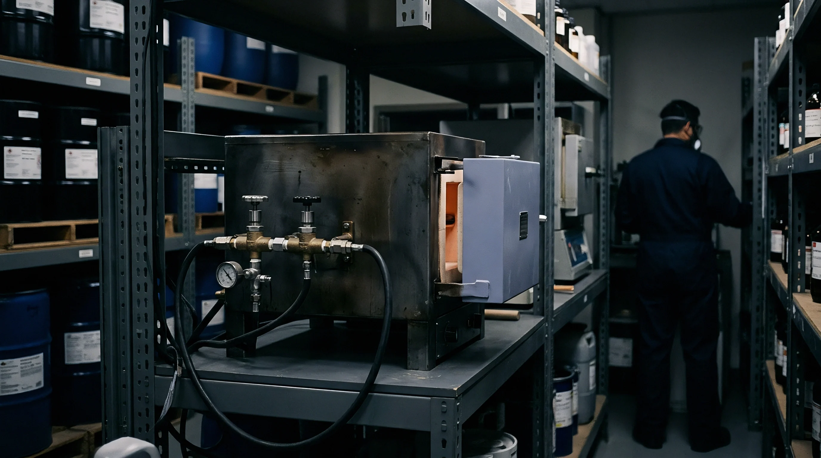
Kiln dynamics, heating ramps, and purge gas velocities govern the carbonization path and final microtexture of hard carbon. Pyrolysis drives off non-carbon elements, leaving a carbonaceous solid while venting water vapor, tar mists, methane, hydrogen, and carbon oxides. Furnace operators must clear these off-gases quickly enough to prevent cracked volatiles from recondensing onto the cooling bed.
Thermal Ramps and Pyrolysis Residence Times
Industrial heating profiles rely on planned isothermal dwells to match specific decomposition stages. Heating from room temperature to 400 degrees Celsius strips moisture and light volatiles, where rates between 1 and 5 degrees Celsius per minute prevent thermal shock and particle clumping. A steady, gentle ramp allows gases to escape through internal channels without fracturing the emerging carbon framework.
Active carbonization occurs between 400 and 1000 degrees Celsius as heteroatom bonds break and mass loss peaks. Polymers decompose into tar vapors and light hydrocarbon gases; maintaining controlled ramps through this range keeps aromatic ring growth disordered. Subsequent holds between 1000 and 1600 degrees Celsius settle the structure, venting residual hydrogen and closing isolated micro-cavities within the bulk.
Inert Gas Environment and Outgassing Dynamics
Running an inert atmosphere inside the kiln stops unwanted combustion and sweeps out heavy tars. Nitrogen or argon purges the hot zone continuously under positive displacement, carrying cracked hydrocarbon vapors into the exhaust before secondary reactions can deposit pyrolytic carbon onto particle surfaces.
- Pre-charge the furnace chamber with high-purity nitrogen gas to reduce ambient oxygen concentration below 10 parts per million.
- Ramp furnace temperature at 2 degrees Celsius per minute to 400 degrees Celsius under a continuous gas flow rate of two chamber volumes per hour.
- Hold at 400 degrees Celsius for 120 minutes to achieve complete outgassing of light volatile compounds and moisture.
- Increase temperature at 5 degrees Celsius per minute to the final carbonization target between 1200 and 1400 degrees Celsius.
- Soak at peak temperature for 240 minutes to induce structural consolidation and close internal pore entrances.
- Cool the reactor under nitrogen atmosphere to below 80 degrees Celsius before exposing the hard carbon powder to ambient air.

Why Does Soaking Time Shape Lattice Spacing?
Sustained heat above 1200 degrees Celsius realigns disordered graphene fragments over time. Extended holds remove dangling bonds and edge flaws, nudging neighboring aromatic clusters into subtle lateral growth and parallel stacking. The interlayer distance expands slightly before settling toward a turbostratic equilibrium around 0.37 to 0.38 nanometers.
Excessive dwell at peak temperature narrows this gap and shrinks closed pore volume, cutting directly into low-potential sodium plateau storage.
Inadequate gas purge velocity during volatile liberation leads to tar re-deposition on cooling particles, permanently reducing initial coulombic efficiency.
Matrix
Microstructure dictates how hard carbon stores charge. The material consists of small, randomly tilted graphitic domains flanked by curved single graphene sheets and closed nanovoids. This layout gives rise to two distinct storage mechanisms: ion adsorption along defect-rich surfaces and disordered graphene sheets, and ion insertion or pore filling inside closed cavities.
Defect levels and interlayer spacing govern both transport rates and total capacity.

Interlayer Spacing and Disordered Graphite Domains
Graphite features an interlayer spacing of 0.335 nanometers, but hard carbon for sodium storage requires a d002 spacing between 0.37 and 0.39 nanometers to allow ion insertion without severe volume expansion. X-ray diffraction shows broad, muted (002) reflection peaks, pointing to short crystallite stacks along the c-axis of only 2 to 5 aromatic sheets. Broad (100) and (110) in-plane peaks confirm that lateral domain dimensions remain under 5 nanometers.
Edge vacancies, Stone-Wales defects, and residual heteroatoms create local states that bind alkali ions between 0.2 and 1.2 Volts against metal reference electrodes. Higher defect counts increase sloping capacity at higher potentials, but they also lower packing density and reduce initial coulombic efficiency through irreversible ion trapping.

Closed Porosity Generation and Surface Area Minimization
High initial coulombic efficiency depends on minimizing external surface area while opening up closed internal pores. Pores exposed to electrolyte solvents generate solid electrolyte interphase, consuming active alkali ions on the initial charge. Carbonizing between 1200 and 1400 degrees Celsius causes crosslinked aromatic sheets to warp and fuse, sealing surface throats and trapping micro-cavities within the bulk carbon.
Heat treatment at 1300 degrees Celsius under high-purity argon reduces BET surface area below 5 square meters per gram while maintaining interlayer spacing above 0.37 nanometers.
| Carbonization Temp (°C) | d002 Interlayer Distance (nm) | BET Surface Area (m²/g) | Closed Pore Volume (cm³/g) | Sloping Capacity (mAh/g) | Plateau Capacity (mAh/g) | First Dwell ICE (%) |
|---|---|---|---|---|---|---|
| 1000 | 0.395 | 45.2 | 0.012 | 180 | 60 | 68.5 |
| 1200 | 0.382 | 8.4 | 0.045 | 130 | 180 | 83.2 |
| 1300 | 0.376 | 3.1 | 0.068 | 105 | 225 | 88.7 |
| 1400 | 0.371 | 1.8 | 0.052 | 90 | 210 | 89.4 |
| 1600 | 0.358 | 1.2 | 0.021 | 65 | 110 | 85.1 |
In carbonization trials moving from 1000 to 1300 degrees Celsius, specific surface area falls from 45.2 to 3.1 square meters per gram as closed pore volume expands from 0.012 to 0.068 cubic centimeters per gram. The primary storage mechanism shifts from high-voltage surface adsorption to low-voltage pore filling, lifting reversible capacity from 240 to 330 milliampere-hours per gram and first-cycle efficiency from 68.5 percent to 88.7 percent. Above 1600 degrees Celsius, incipient graphitization collapses closed voids and narrows crystallite spacing, sharply reducing sodium uptake.
Poor batch-to-batch initial coulombic efficiency frequently traces back to improper furnace soak calibration rather than seasonal moisture variations in precursor feedstocks.

Sodium
Sodium insertion into hard carbon proceeds in two steps visible on galvanostatic charge-discharge curves. The sloping profile from 1.2 Volts down to roughly 0.1 Volts marks sodium adsorption onto defect sites and disordered graphene sheets. The flat plateau below 0.1 Volts represents intercalation between turbostratic layers and sodium clustering in closed nanopores.
Balancing this split between sloping and plateau capacity drives both thermal profile design and cell matching.
Sloping Capacity Adsorption versus Plateau Insertion
Sloping capacity delivers fast reaction kinetics with minimal volume strain, which suits high-power cells, though it lowers average cell voltage and volumetric energy density. Plateau capacity operates near the potential of metallic sodium, offering higher working voltage and energy density at the cost of slower diffusion and greater risk of metal plating under fast-charging or freezing conditions.
Lowering carbonization temperatures leaves more defects in place, favoring sloping capacity. Raising the temperature consolidates the carbon network, lowering accessible surface area, expanding closed pores, and shifting output into the low-voltage plateau. A carbonization window between 1250 and 1350 degrees Celsius generally strikes the best balance between overall capacity and rate response.
Electrolyte Interaction and Passivation Film Growth
Exposing fresh hard carbon to non-aqueous liquid electrolytes decomposes solvent molecules and conducting salts on active surfaces. This reduction step forms the solid electrolyte interphase, locking up sodium ions and reducing first-cycle efficiency. Carbonate solvents like ethylene carbonate and diethyl carbonate blends react heavily with surface heteroatoms, growing thicker passivation films than ether formulations.
Incorporating an explicit maximum limit of five square meters per gram for BET surface area into purchase contracts forces vendors to verify thermal stabilization completeness before lot release.
Comparing precursor types and furnace runs against commercial requirements relies on a standard set of physical metrics:
- Specific Surface Area Threshold demands nitrogen adsorption surface area below 5 square meters per gram to restrict solid electrolyte interphase formation and preserve active sodium inventory.
- Interlayer Spacing Lower Bound enforces d002 crystal lattice dimensions above 0.37 nanometers to guarantee unhindered sodium insertion without kinetic bottlenecks.
- True Density Calibration requires helium pycnometry values between 1.45 and 1.60 grams per cubic centimeter, confirming adequate closed void generation without microstructural density loss.
- Residual Hydrogen Content Ceiling sets elemental hydrogen concentrations below 0.2 percent by weight, preventing active site blockage and voltage hysteresis.
Contractually enforcing surface area thresholds remains the primary commercial safeguard against high irreversible capacity loss.
Assay
Receiving inspection for hard carbon requires tight analytical checks on chemical purity, microtexture, and lot consistency prior to slurry mixing. Unreacted inorganic ash acts as inactive ballast and can catalyze parasitic electrolyte reactions during cycling. Procurement specifications balance these purity requirements directly against raw material and processing costs.
Ash Contamination and Residual Elemental Impurities
Bio-based precursors carry varying levels of inorganic ash, largely silica, alumina, iron oxides, and alkali salts. Silica provides zero sodium storage, while iron and transition metals risk internal micro-shorts or catalyze solvent degradation. Bio-derived commercial grades typically undergo hydrochloric or hydrofluoric acid washing to pull inorganic minerals below 0.1 percent by weight.
Trace metals are verified by inductively coupled plasma optical emission spectroscopy. Moisture picked up during transport or warehousing requires oven drying at 110 degrees Celsius before electrode compounding, as residual water reacts with electrolyte salts to produce hydrofluoric acid and degrade passivation layers.

Processing Energy Balance and Mass Economics
High-temperature carbonization represents over 60 percent of hard carbon powder manufacturing costs. Long furnace dwell times at extreme temperatures drive heavy power usage, making precursor mass yield a decisive commercial factor. Carbohydrates yield around 25 percent carbon, requiring high incoming raw volumes, whereas pitch and synthetic resins consistently yield over 50 percent.
Commercial viability hinges on balancing high precursor carbon yields with low thermal energy demands during high-temperature carbonization.
| Precursor Stream | Raw Feedstock Cost ($/kg) | Thermal Carbonization Yield (%) | Energy Demand (kWh/kg output) | Purification Cost ($/kg) | Final Powder Cost ($/kg) | Cell Level Cost ($/kWh) |
|---|---|---|---|---|---|---|
| Coconut Shell Bio-Char | 0.80 to 1.20 | 30 to 34 | 14 to 18 | 1.20 to 1.60 | 5.50 to 7.20 | 16.50 to 21.60 |
| Purified Phenolic Resin | 3.50 to 4.80 | 52 to 58 | 10 to 13 | 0.00 to 0.20 | 9.80 to 12.50 | 29.40 to 37.50 |
| Air-Blown Petroleum Pitch | 1.10 to 1.60 | 68 to 74 | 8 to 11 | 0.50 to 0.80 | 4.20 to 5.80 | 12.60 to 17.40 |
| Dehydrated Hydrochar | 1.50 to 2.20 | 38 to 44 | 12 to 15 | 0.80 to 1.10 | 6.80 to 8.90 | 20.40 to 26.70 |
Synthetic resins deliver high yield and negligible ash, but their raw cost confines them to premium cells. Petroleum pitch offers high carbon yield at lower material cost, though it demands dedicated oxidation equipment to prevent graphitization. Coconut shells provide an accessible middle ground if acid washing cleanly removes silica and iron.
Procurement ultimately balances these yield losses against delivered electrochemical stability.