Solid State Cell Initial Stack Pressure Baseline Qualification Procedures
Solid-state cell qualification demands matching fixture compliance to anode expansion profiles while holding stack pressure decay below 0.05 MPa per 100 hours.


Rig
Solid-state pouch cells with sulfide-based inorganic electrolytes require continuous, uniform perpendicular force across the active area to prevent voiding and delamination during lithium stripping and plating. If ionic contact degrades at the solid electrolyte interface, localized current density spikes, pushing metallic lithium dendrites through microscopic voids in the ceramic separator. Baseline stack pressure qualification checks that test fixtures apply uniform compression without creating parasitic shear vectors or bending moments across the pouch.
Acceptance testing starts with the structural chassis. Fixtures built from unhardened aluminum plates flex under multi-kilonewton loads, concentrating force near the outer bolt lines and unloading the center of the active area. To maintain uniform ionic flux across the cell, deflection across the top and bottom load plates must stay below 0.012 millimeters at maximum qualification pressure.
Parallelism deviation across a 200 millimeter by 150 millimeter platen area cannot exceed 0.025 millimeters under full clamp load.
Force delivery mechanisms fall into two categories: passive spring-loaded stacks and active servo-hydraulic or electromechanical actuators. Passive fixtures use calibrated Belleville disc springs, wave springs, or coil springs held under fixed mechanical compression. Active fixtures rely on closed-loop load cells tied to drive screws or hydraulic cylinders, maintaining target pressure as cell thickness changes during cycling.
Passive spring stacks provide long-term stability without external power, but their restoring force alters as the cell expands and contracts. A cell expanding 8 percent in thickness during charge compresses a passive spring stack further, driving stack pressure above the target setpoint unless spring compliance is tuned to match the expected expansion profile.

Mechanical Fixture Deflection and Force Vector Alignment
Planar alignment errors create high-pressure zones around the pouch perimeter, causing edge failures and uneven lithium plating. Calibration requires dual-plane pressure mapping with thin-film piezoresistive sensor arrays placed between the platen face and a calibrated elastomeric pad. The pad matches the compliance of raw pouch materials, separating fixture planarity errors from surface micro-roughness.
Load cells in qualification rigs must sit on the central force axis. Single-point sensors mounted off-center introduce bending moments into the guide pins, causing linear bearings to bind. This binding generates frictional hysteresis that corrupts force readings, creating a gap between the transducer reading and the actual force on the cell stack.
A fixture platen displaying 0.030 millimeters of center deflection creates a 35 percent pressure drop at the cell core relative to its clamped edges.
Guide post alignment requires precision linear ball bearings or ground dowel pins hardened to 60 Rockwell C. Standard commercial bushings allow rotational play that lets platens skew under load. Skew angles as small as 0.05 degrees convert vertical clamping force into lateral shear across the solid electrolyte, degrading contact and cracking brittle ceramic separators.
Thermal isolation between heating elements and load transducers prevents calibration drift during high-temperature testing. Sulfide cells undergo baseline qualification at 45 degrees Celsius or 60 degrees Celsius to boost ionic conductivity. Unshielded load cells exposed to thermal radiation from heated platens suffer zero-point drift, corrupting baseline pressure metrics over multi-week tests.

Tooling and Mechanical Rig Failure Modes
Pre-qualification verification identifies potential failure modes before cell trials start. Fixture components undergo stress screening to catch assembly, material, and alignment faults.
- Platen Bowing Under Load center deflection exceeds parallelism limits, creating non-uniform ionic current distribution and early stripping failure at the cell center.
- Linear Bearing Binding friction along guide shafts masks cell thickness changes, causing actual stack pressure to drift from values reported by the primary force sensor.
- Belleville Spring Pack Hysteresis internal friction between spring washers alters force output during contraction, leaving pressure lower during cell discharge than during charge.
- Thermal Transducer Drift uncompensated heating of load cell strain gauges causes baseline drift, recording false pressure changes during isothermal holds.
- Threaded Fastener Creep torque loss in clamping studs relaxes spring compression over extended cycling, leading to interface delamination.
Torque loss on un-lubricated grade 8 steel studs accounts for up to 14 percent pressure relaxation within 72 hours of initial fixture setup. Hardened washers and thread lubricant stabilize preload retention during thermal cycling.
Off-center force readings during initial clamp-down stem from normal pouch thickness variations or fixture assembly tolerances.


Compliance
Mechanical compliance governs how the fixture responds to dimensional changes inside the cell during charge and discharge. Solid-state chemistries with pure lithium anodes show significant thickness variation as lithium plates and strips. A 20 Ah pouch cell with a pure lithium anode can expand by 20 to 100 micrometers, depending on initial anode thickness and state of charge.
If cell expansion meets an overly rigid clamp, stack pressure rises rapidly, exceeding yield limits and crushing porous cathode structures or ceramic separators. Conversely, a soft clamping setup lets stack pressure drop below the threshold needed for interfacial contact during stripping, causing rapid capacity fade and void formation.
Establishing baseline compliance requires measuring the spring rate of the complete stack, including end plates, insulation sheets, heating elements, shim stock, force distribution pads, and internal load sensors. System compliance is then tuned to match the cell chemistry under test.

Pressure Baseline Specifications across Solid State Chemistries
Solid-state electrolyte formulations require distinct baseline pressure regimes and dynamic compliance windows. Sulfides have lower shear moduli and higher plasticity, maintaining interface contact at moderate pressures. Oxide electrolytes possess high elastic moduli, resisting deformation and demanding precise planar compliance to prevent stress concentrations that crack the ceramic.
| Electrolyte Class | Typical Baseline Pressure (MPa) | Max Allowable Pressure Peak (MPa) | System Compliance Target (mm/MPa) | Operating Temperature Range (°C) |
|---|---|---|---|---|
| Sulfide (LPSCl / Argyrodite) | 1.0 to 5.0 | 8.0 | 0.015 to 0.035 | 15 to 60 |
| Oxide (LLZO / NASICON) | 0.1 to 1.5 | 3.0 | 0.005 to 0.015 | 20 to 80 |
| Halide (Li3YCl6 derivatives) | 2.0 to 7.0 | 10.0 | 0.010 to 0.025 | 20 to 45 |
| Polymer-Matrix Hybrid | 0.2 to 1.0 | 2.5 | 0.040 to 0.080 | 40 to 80 |
Interfacial contact resistance in sulfide cells drops exponentially as initial stack pressure increases from 0.1 MPa to 2.5 MPa. Beyond 5.0 MPa, performance gains diminish, and the risk of short circuits from lithium driving through separator micro-cracks rises sharply.
Oxide systems require low baseline pressures because high mechanical loads fracture brittle garnet separators. Polymer-matrix hybrid cells use elevated temperatures to soften the polymer phase, allowing lower stack pressures to maintain ionic contact across composite boundaries.

Fixturing Spring Mechanics and Load Balance Calculations
Spring rates for passive compression fixtures follow series-spring equations. Total stack displacement equals the sum of the individual displacements of each component under load.
Total system stiffness follows the reciprocal formula:
1 / K_system = (1 / K_plates) + (1 / K_springs) + (1 / K_pads) + (1 / K_cell)
Where K_system represents overall fixture spring rate, K_plates represents structural plate stiffness, K_springs represents clamping spring stiffness, K_pads represents compliance pad stiffness, and K_cell represents transverse cell elastic modulus.
When K_springs dominates system compliance, pressure variations stay controlled during volume changes. Designing K_springs well below K_plates ensures that thickness increases produce minimal pressure spikes across the active cell face.
A sulfide cell stack operating under 5.0 MPa pressure exhibits a 2.3 percent loss in capacity per hundred cycles for every 1.0 MPa drop below its initial pressure baseline.
Cell swelling forces measured on active electromechanical load frames establish dynamic stiffness targets. The collected load-displacement curves allow tuning of passive spring packs for pilot volume qualification testing.
Selecting incorrect compliance parameters damages the solid electrolyte matrix during charge and causes loss of interfacial contact during discharge, ending cell operating life prematurely.


Swell
Volume changes in solid-state pouch cells show up primarily as thickness expansion perpendicular to the electrode layers, with minor planar expansion along length and width. Linear displacement sensors measuring perpendicular movement must separate cell expansion from thermal expansion of fixture components, as heated platens can introduce false displacement signals into logs.
High-precision rigs use dual optical displacement sensors or differential LVDTs mounted on low-thermal-expansion invar frames. Displacement resolution must reach 0.1 micrometers to capture structural shifts from phase transitions in cathode materials and early stage lithium plating.
Dynamic thickness changes during charging follow two phases: linear expansion from lithium deposition at the anode interface, and non-linear expansion driven by cathode lattice volume changes and potential gas evolution. Qualification protocols track displacement profiles against capacity throughput to spot abnormal swelling early.

Zero-Point Calibration and Pre-Load Stabilization
Establishing a repeatable zero point is required before running qualification sweeps. Pouch materials have surface irregularities, seal wrinkles, and internal gas pockets that cause non-linear load-displacement curves at low force levels.
The sequence below establishes standardized zeroing and pre-load stabilization before logging baseline qualification data.
- Mount the uncharged solid-state cell centrally between cleaned fixture platens using clean-room gloved tools.
- Install calibrated piezoresistive pressure mapping film between cell surface and platen face to verify force distribution uniformity.
- Apply an initial seating load of 0.05 MPa to collapse pouch surface wrinkles and align internal current collector foils.
- Dwell at seating load for 300 seconds while monitoring linear displacement sensors for mechanical creep saturation.
- Ramp compression force at a constant rate of 0.1 MPa per second until reaching target baseline qualification pressure.
- Hold target baseline pressure for 1,800 seconds to achieve mechanical equilibrium across cell, compliant pads, and load sensor train.
- Zero all displacement transducers and load cell channels in data acquisition software.
- Execute three minor force cycles of plus or minus 10 percent target baseline force to verify fixture return elasticity without hysteresis offset.
Completing this sequence ensures subsequent displacement logs measure true cell expansion rather than initial mechanical settling within the fixture.
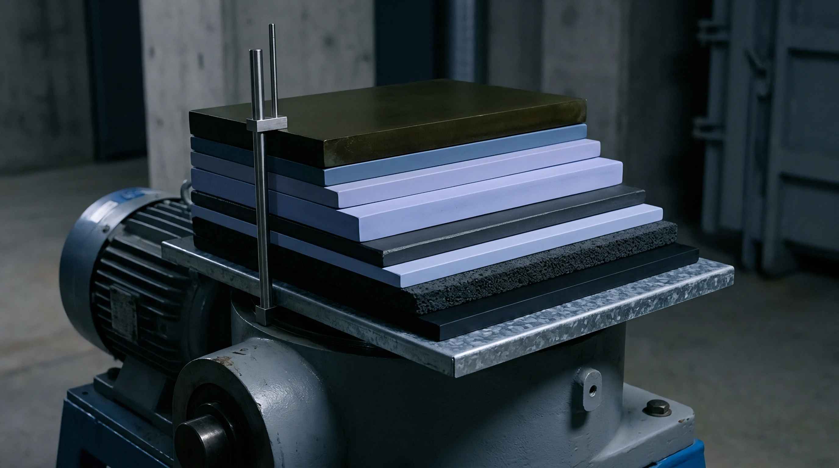
Translational Displacement and Thickness Mapping
Local electrode thickness variations create non-uniform pressure across cell surfaces during high-rate cycling. Dense regional lithium deposition increases local stack pressure, accelerating mechanical creep in adjacent solid electrolyte zones.
Mapping local thickness variations requires multi-point displacement arrays across the top platen. Nine-point displacement grids reveal saddle- or dome-shaped deformation during fast charging, pointing to localized current density crowding.
Planar thermal gradients across fixture platens exacerbate non-uniform swelling. A 3 degrees Celsius temperature gradient across a 200 millimeter active area alters local electrolyte conductivity enough to concentrate lithium deposition in warmer zones, driving thickness spikes that distort force readings.
Dynamic compression systems actively adjust fixture gap distance to maintain fixed force baselines. Active gap management tracks displacement speed, yielding diagnostic data on solid-state reaction kinetics and phase transition rates during charge and discharge.
Stabilize test cell temperature within a 0.5 degree Celsius band before recording zero-point thickness metrics.


Hysteresis
Load cells, spring packs, and cell materials all exhibit mechanical hysteresis, absorbing and dissipating energy during loading and unloading. When a cell expands during charge and contracts during discharge, the force-displacement path during stripping deviates from the path recorded during plating.
Strain gauge load sensors suffer from intrinsic mechanical and thermal hysteresis. Piezoresistive sensors show higher thermal drift, whereas capacitive sensors offer better stability but need shielding from high-frequency electromagnetic interference generated by environmental chamber compressors and cycling power supplies.
Elastomeric compliance pads placed between platens and cell pouches introduce high viscoelastic hysteresis. Silicone rubbers, fluoroelastomers, and polyurethane foam pads absorb mechanical energy, shifting baseline compression forces over consecutive deep cycles. Metallic spring packs exhibit far lower hysteresis than polymer pads, making them preferable for long-term qualification testing.

Load Sensor Drift and Calibration Budgets
Accurate baseline measurement over extended qualification campaigns requires strict sensor calibration budgets. Instrumentation drift corrupts pressure decay analysis, masking cell-level force relaxation under continuous load.
| Error Source | Piezoresistive Array | Strain Gauge S-Beam | Capacitive Load Cell | Target Budget Limit |
|---|---|---|---|---|
| Non-Linearity (% Full Scale) | ± 1.50 | ± 0.05 | ± 0.10 | ± 0.10 |
| Hysteresis (% Full Scale) | ± 2.00 | ± 0.03 | ± 0.08 | ± 0.05 |
| Thermal Zero Drift (% FS/°C) | ± 0.25 | ± 0.015 | ± 0.005 | ± 0.010 |
| Long-Term Drift (% FS/1000h) | ± 3.50 | ± 0.10 | ± 0.05 | ± 0.10 |
| Cross-Axis Sensitivity (%) | ± 4.00 | ± 0.50 | ± 0.20 | ± 0.50 |
Piezoresistive mapping films provide high spatial resolution across active cell areas, but long-term drift and thermal sensitivity make them unsuited for continuous force logging. S-beam strain gauge sensors mounted outside thermal zones maintain low drift over extended cycling.
Capacitive load sensors deliver lower thermal sensitivity, preserving baseline tracking precision during aggressive thermal step protocols. Off-axis forces from non-uniform swelling introduce errors unless decoupling ball joints or low-friction spherical seats isolate the primary transducer axis.
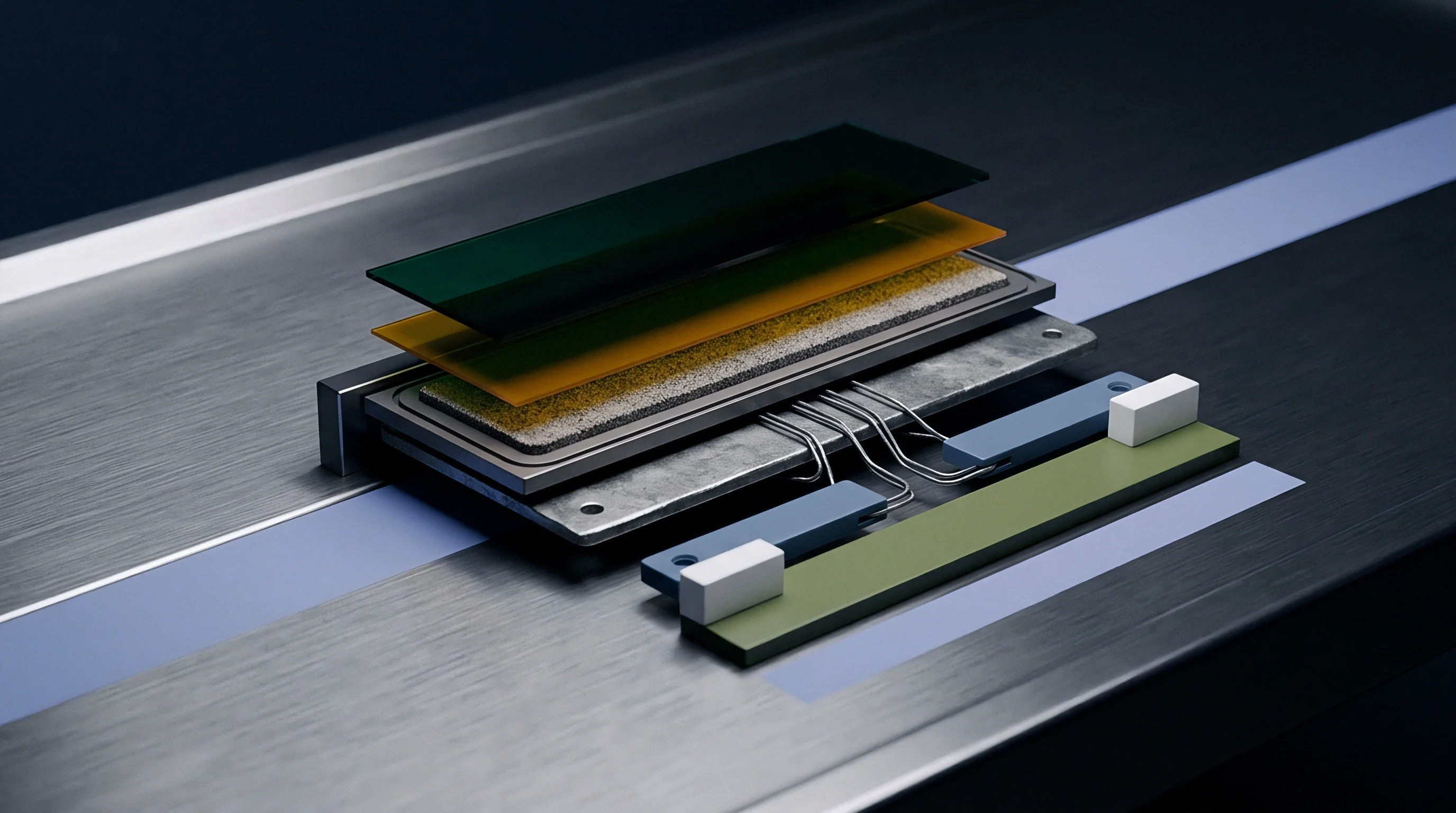
Dynamic versus Fixed Load Qualification Decisions
Choosing between active dynamic pressure control and passive fixed-gap testing is a core decision in baseline qualification methodology. Each configuration highlights different failure modes in solid-state cell designs.
Dynamic force control adjusts fixture position to hold stack pressure constant throughout cycling. This isolates electrochemical performance from swelling-induced pressure increases, giving clear capacity baseline metrics under fixed thermodynamic conditions.
Fixed-gap qualification locks fixture platens at a set baseline distance after pre-loading, letting stack pressure rise as the cell expands. This replicates rigid pack enclosures, testing whether internal cell layers withstand peak compressive stress without shorting.
- Active Force Control Mode maintains constant interfacial pressure, preventing void formation during stripping while eliminating stress build-up during peak charge expansion.
- Fixed Platen Distance Mode exposes cell components to rising mechanical stress during charge, identifying structural failure limits of ceramic separators under volumetric constraints.
- Passive Spring Compliant Mode balances mechanical complexity and compliance, allowing controlled pressure increases that mimic engineered spring packs in commercial modules.
- Step-Wise Pressure Sweeping evaluates electrochemical performance across discrete pressure increments, identifying the minimum force needed to prevent voiding at targeted C-rates.
A sulfide cell locked in a fixed-gap test fixture starting at a 1.5 MPa baseline setpoint reached a 4.2 MPa pressure peak during fast charging. The resulting stress caused localized electrolyte cracking and short-circuit failure at cycle 140.
Thermal compensation prevents cell crushing during rapid charging.
Rapid charging generates internal heat, expanding structural components and active layers simultaneously. Active temperature compensation algorithms in electromechanical drive systems adjust gap distance to subtract fixture thermal expansion from cell swelling signals. Without thermal compensation, fixture thermal expansion masks cell swelling dynamics, leading to inaccurate force control loop responses that compromise baseline qualification.
The exact structural mechanism causing internal load cells to register false pressure drop signals during high-temperature dwell periods remains an open question in rig design.


Relaxation
Stack pressure retention degrades over time as materials within the cell and fixture undergo stress relaxation under constant displacement. Solid electrolytes, polymeric binders, separators, and gaskets show time-dependent plastic flow and creep. Identifying the rate of baseline pressure loss under stationary mechanical conditions is essential for predicting multi-year pack stability.
Initial stress relaxation occurs rapidly during the first 24 to 72 hours after applying baseline force. Polymeric components like pouch laminate films and internal gel-polymer phases flow into micro-voids, dropping stack pressure by 5 to 15 percent before settling into a logarithmic decay curve.
Elevated temperatures accelerate material creep exponentially following Arrhenius relationships. A baseline qualification test conducted at 60 degrees Celsius exhibits stress relaxation kinetics five to eight times faster than identical tests at 22 degrees Celsius, requiring pre-conditioned mechanical stabilization before baseline recording begins.

Viscoelastic Creep in Solid Cell Components
Sulfide electrolyte layers contain ductile microstructures that deform under continuous pressure. While micro-plasticity helps heal void defects along active interfaces, unconstrained lateral creep causes thin films to migrate toward pouch edges, reducing separator thickness and increasing short-circuit risk.
Separator compression testing measures thickness loss under sustained baseline loading over extended periods. A sulfide electrolyte film subjected to 5.0 MPa pressure at 45 degrees Celsius can lose 3 to 8 percent of its initial thickness over 1,000 operating hours through cold-flow mechanisms.
Section 4.3 of baseline qualification contract standard SC-882 specifies that pressure decay under static mechanical dwell cannot exceed 0.05 MPa per 100 hours after initial 72-hour burn-in stabilization.
Pouch edge seals represent another source of creep. Thermoplastic seal layers compressed under platens slowly yield over time, allowing end plates to close slightly and lowering spring displacement. Incorporating hard mechanical stops outside the active seal zone prevents fixture force from deforming seal materials while maintaining uniform compression across active electrode areas.

Qualification Dossier Requirements and Contract Specifications
Baseline pressure qualification data forms a core component of the engineering dossier delivered to downstream pack integrators. Missing or incomplete relaxation profiles lead to disputes regarding cell quality during pack integration.
- Initial Static Pressure Decay Curve minimum 168-hour log showing force loss under uncharged isothermal conditions to isolate mechanical relaxation from electrochemical volume changes.
- Multi-Temperature Creep Coefficients stress relaxation rates measured at 20, 45, and 60 degrees Celsius to enable thermally accelerated lifetime modeling of module clamping systems.
- Dynamic Pressure Hysteresis Loops force versus displacement plots captured across complete charge-discharge cycles at 0.1C, 0.5C, and 1.0C rates.
- Spatial Pressure Uniformity Maps piezoresistive sensor scans proving planar force variance remains within plus or minus 10 percent of target setpoint.
- Post-Test Platen Parallelism Audit dimensional report confirming fixture end plates maintained flatness tolerances without permanent structural deformation after cycling.
These metrics establish acceptable pressure tolerances for incoming cell batch acceptance testing. Batches exhibiting initial pressure relaxation rates above certified limits are rejected before entering pack assembly lines.
Standard qualification clause 12-B of supply contract SC-882 states that any cell batch exhibiting a baseline pressure drop exceeding 12 percent over 168 hours of static dwell at 45 degrees Celsius forfeits cell manufacturer compliance certification.


Settlement
Mechanical settlement during initial formation cycling alters the baseline pressure profile of solid-state cells before they enter commercial qualification loops. Primary formation cycles induce chemical transformations, phase changes, and lithium plating that permanently alter cell thickness and compliance.
During first charge, lithium plates onto the anode substrate, forcing the cell structure open and compressing compliant internal layers. On initial discharge, lithium stripping leaves microscopic pores along the interface if stack pressure cannot drive plastic deformation of the lithium or sulfide electrolyte back into the voids. This permanently alters the cell’s uncharged resting thickness.
Unstabilized cells show high cycle-to-cycle variance in measured force during qualification. Executing mechanical pre-conditioning cycles at low C-rates under high formation pressure consolidates internal cell interfaces, establishing a stable thickness baseline before qualification logging begins.
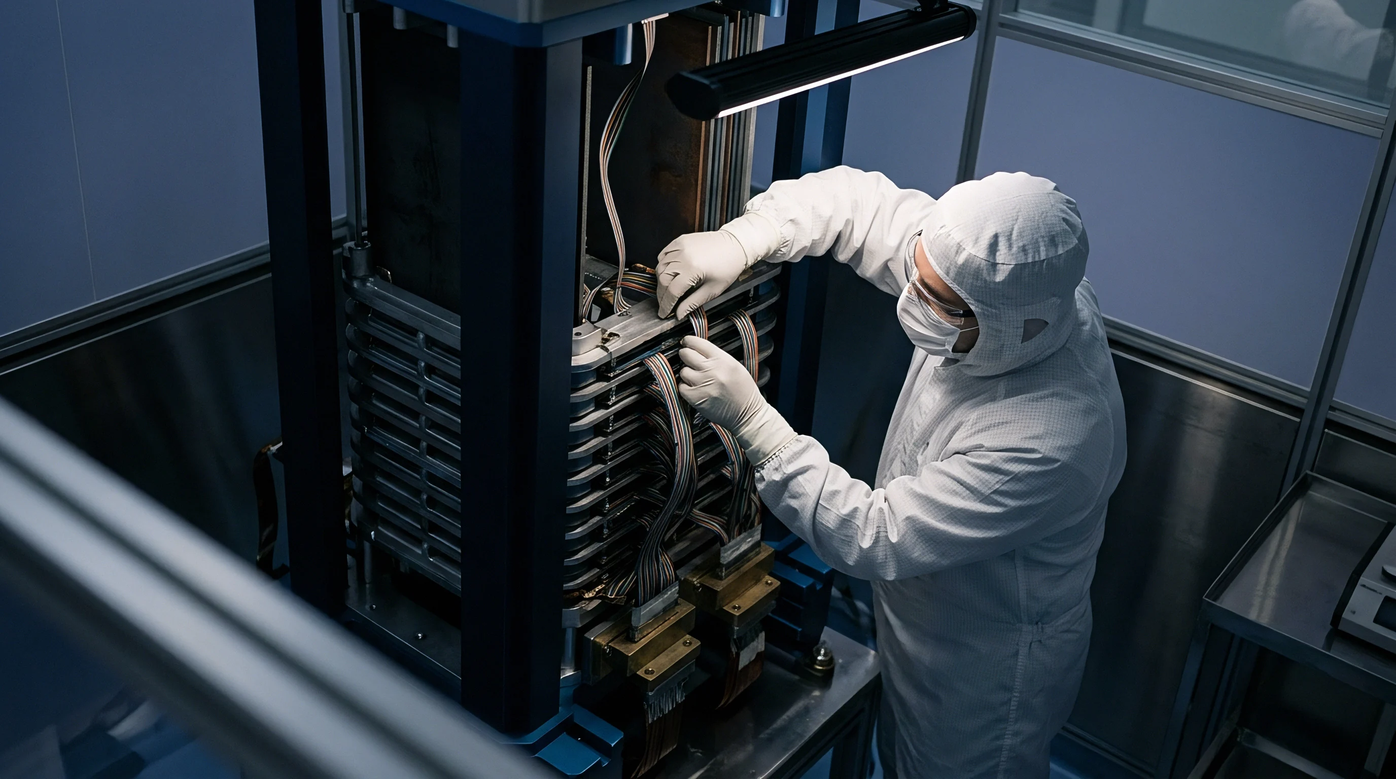
Module Retorque Tolerances and Assembly Arithmetic
Integrating qualified cells into multi-cell modules requires converting single-cell qualification parameters into pack-level mechanical designs. Module spring packs must accommodate cumulative tolerances across stacked cells while keeping individual cell pressure baselines within target limits.
| Component / Parameter | Nominal Dimension (mm) | Tolerance Standard (mm) | Worst-Case Stack (mm) | RSS Probability Stack (mm) |
|---|---|---|---|---|
| Cell Resting Thickness (×12) | 48.000 | ± 0.600 | ± 0.600 | ± 0.173 |
| Inter-Cell Insulators (×13) | 13.000 | ± 0.130 | ± 0.130 | ± 0.036 |
| Thermal Cold Plate (×2) | 10.000 | ± 0.100 | ± 0.100 | ± 0.071 |
| End Compression Plates (×2) | 30.000 | ± 0.150 | ± 0.150 | ± 0.106 |
| Total Mechanical Stack | 101.000 | ± 0.980 | ± 0.980 | ± 0.220 |
Root-sum-square calculations show that probabilistic manufacturing variations remain far smaller than worst-case stack-up scenarios. Designing spring travel for the root-sum-square tolerance band prevents excessive baseline pressure variation across volume production runs.
Properly engineered module spring rates keep manufacturing variations across a 12-cell series stack under a 5 percent deviation from target initial pressure baselines. High spring stiffness converts minor dimensional variations into large pressure offsets, causing premature cell failure in out-of-spec module slots.
Landed Cost Implications of Pressure Qualification Rigs
Establishing solid-state baseline qualification capabilities requires capital expenditure for test channels and mechanical fixturing. High-precision active electromechanical test channels cost significantly more than passive spring clamping fixtures.
Passive baseline qualification fixtures cost between $1,200 and $3,500 per channel, incorporating precision spring packs, load cells, invar frames, and integrated heating platens. Active servo-hydraulic systems run between $15,000 and $40,000 per channel, limiting their use to initial NPI qualification while passive fixtures handle volume validation banks.
Amortizing fixture hardware over qualification unit volumes shows that thorough baseline qualification adds between $0.45 and $1.20 per kilowatt-hour to cell landed qualification budgets. This cost is offset by avoiding field failures from improper clamping pressure.
Designing spring pack travel to cover three times the calculated root-sum-square stack tolerance prevents premature pressure saturation during cell life.
Module assembly yield reflects the rigor of incoming baseline pressure qualification protocols. Screening out cells with irregular thickness expansion or high pressure relaxation rates protects downstream assembly, ensuring finished solid-state packs maintain target stack pressure throughout their operating life.