Cylindrical Cell Integration Guidelines for Low Volume Pack Assemblies
Low volume cylindrical pack builds require strict cell sorting, optimized micro-joining, off-the-shelf cell matrices, and early compliance planning to control NRE expenses.

Selection
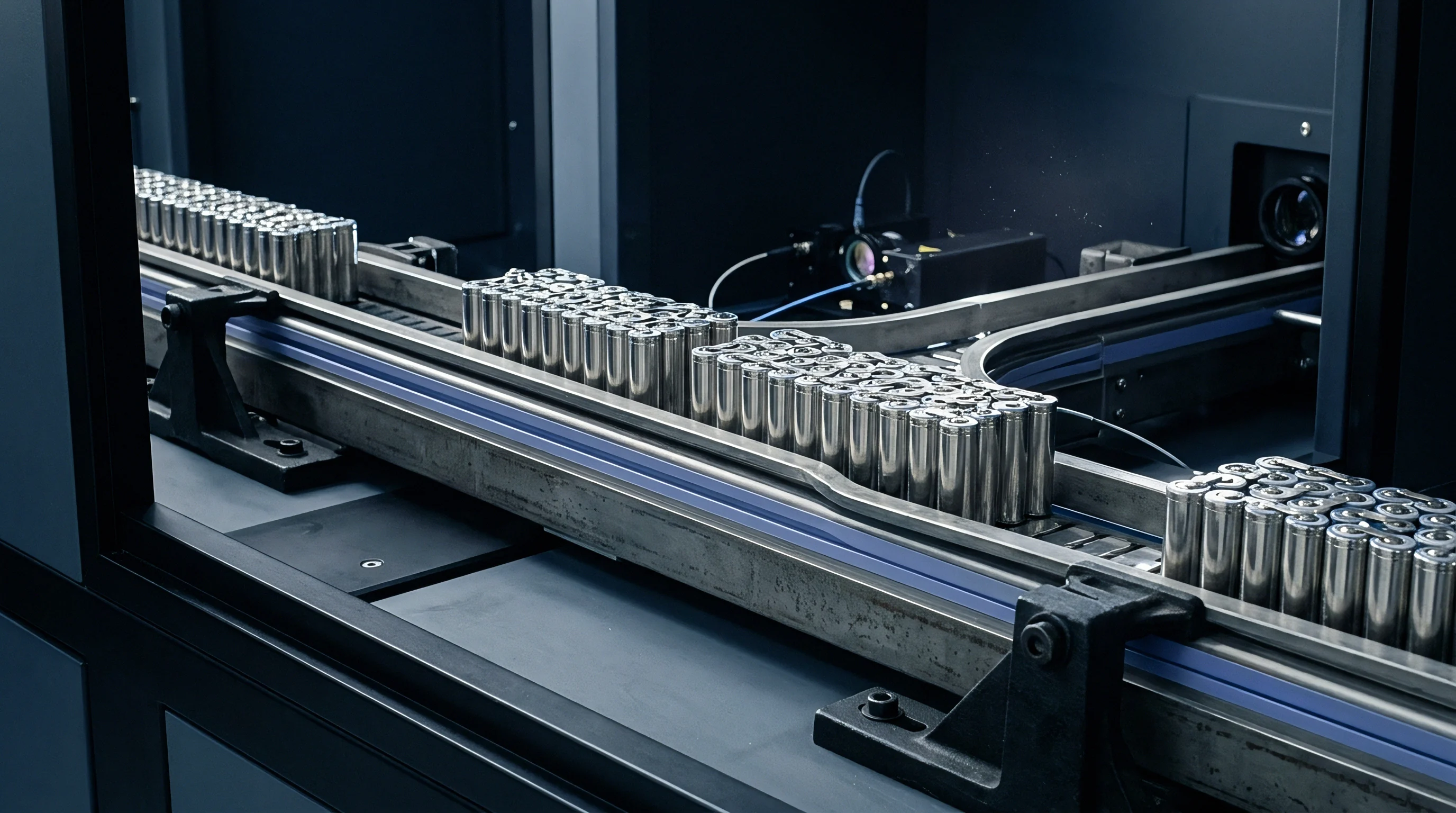
Selecting small cylindrical cells for low-volume pack builds comes down to balancing discharge capacity, energy density, and supply availability. Annual runs of one hundred to five thousand packs rarely command the custom chemistries or dedicated factory lines reserved for automotive OEMs. Integration relies instead on commercial off-the-shelf formats ~ mainly 18650, 21700, and newer 4680 cells.
Aligning cell chemistry and geometry with the load profile, alongside tight incoming quality control, is the main hedge against field failure.

Form Factor Tradeoffs
Each small cylindrical format brings specific mechanical and electrical trade-offs to low-volume designs. The 18650 remains widely available, uses mature tooling, and keeps individual cell costs down, though scaling to larger capacities requires extensive parallel interconnects that hurt overall density. Moving to 21700 cells increases volume by forty-seven percent and boosts energy capacity by up to fifty percent.
The larger diameter retains more heat at the core under high discharge rates, generating a steeper radial thermal gradient that internal pack structures have to handle.
The 4680 format shifts both structural and thermal dynamics. Tabless construction cuts internal resistance, but holding mechanical tolerances across large cans demands rigid module framing. For low-volume builds, 4680 cells often raise mechanical integration expenses because off-the-shelf structural matrices remain scarce, offsetting the raw volumetric savings shown on cell datasheets.
| Format | Nominal Capacity (Ah) | Volumetric Energy (Wh/L) | AC Internal Resistance (mΩ) | Mass per Unit (g) |
|---|---|---|---|---|
| 18650 NMC | 3.5 | 670 | 18.0 | 48 |
| 21700 NMC | 5.0 | 710 | 12.5 | 69 |
| 21700 LFP | 3.0 | 420 | 22.0 | 70 |
| 4680 NMC | 25.0 | 680 | 2.5 | 355 |
| Data measured at 20 degrees Celsius using 1 kHz AC impedance analyzer on standard commercial cells. | ||||
Grade a Cell Sorting Criteria
Sourcing cells through secondary distributors introduces variations in both capacity and internal resistance. Major manufacturers grade cells during production and reserve tier-one output for long-term contract buyers, leaving spot markets with mixed production runs or secondary grades. Assembling unsorted cells into series-parallel strings causes premature capacity loss and uneven thermal stress, which low-cost battery management balancing circuits cannot fully correct.
Low volume production runs disproportionately suffer from cell lot variation due to purchasing spot-market inventory rather than locked tier-one factory contracts.
Incoming inspection sets the baseline for every batch, catching out-of-spec cells before assembly starts. For 21700 NMC cells, internal resistance targets 12.5 milliohms with an allowable tolerance of plus or minus 0.8 milliohms when measured at 1 kilohertz AC at 20 degrees Celsius across a 50-unit sample. Storage conditions also play a heavy role: unconditioned storage results in calendar degradation between 1.5 percent and 4.2 percent capacity loss per year.
Given that uncertainty, receiving checks should include one hundred percent screening for open-circuit voltage and AC impedance.
- Voltage Delta Variance Open-circuit voltage outside a fifteen-millivolt window points to unequal self-discharge during storage or internal shunt paths.
- AC Internal Resistance Offset Impedance shifts over eight percent from the lot median indicate cathode structural damage or tab welding defects.
- Self-Discharge Rate Drift Voltage loss exceeding two millivolts over a thirty-day rest period indicates separator contamination.
Minor voltage discrepancies across a received pallet often reflect extended storage rather than uneven self-discharge rates, though pack builders typically perform balancing cycles before module assembly.

Weld
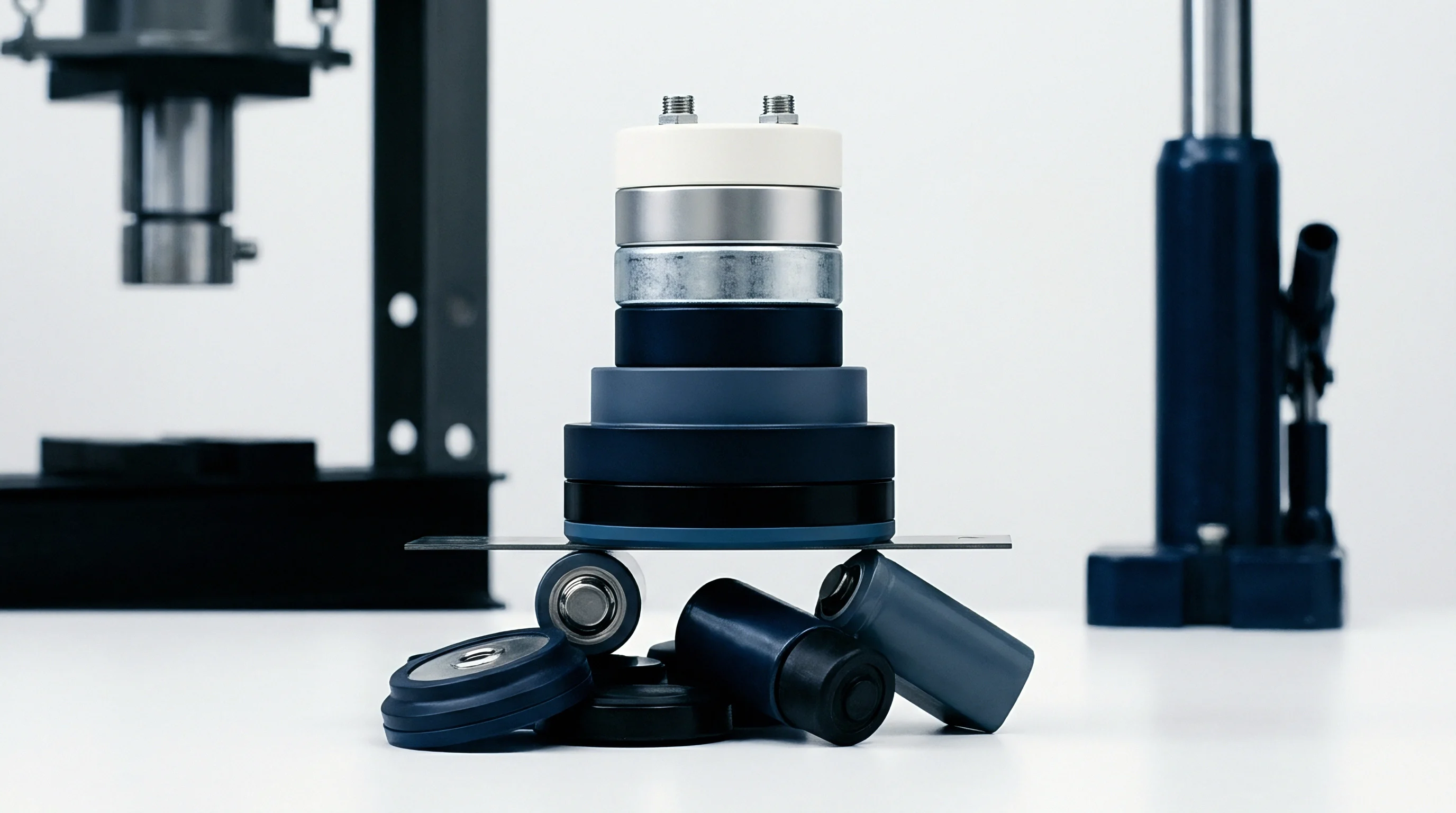
Joining cells into series and parallel strings requires careful metallurgical control. Low-volume operations must select joining methods that balance equipment investment against joint resistance and mechanical strength. Standard soldering irons dump too much heat into the top vent seal, melting internal safety gaskets and leaking electrolyte.
Micro-spot welding and fiber laser welding serve as the standard choices for cylindrical cell interconnects.

Spot Resistance versus Laser Joining
Micro-joining processes differ markedly in initial equipment cost and electrical performance. Resistance spot welding applies pneumatic pressure and controlled current pulses to join metal tabs to cell terminals. Capital costs are low, making it practical for short production runs.
Heat generated at the resistance interface forms the weld nugget, though excessive pulse energy can push projections through the thin top cap and puncture the internal current collector. Keeping pulse duration under fifteen milliseconds prevents thermal damage.
Fiber laser welding uses focused optical energy to produce high-aspect-ratio fusion zones with minimal heat-affected area and low joint resistance. However, a five-axis laser welding cell costs an order of magnitude more than a spot welder. Low-volume programs usually work around this capital barrier by outsourcing to specialized battery welding contractors or using manual desktop micro-laser systems.
| Conductor Material | Thickness (mm) | Joining Method | Shear Strength (N) | Joint Resistance (mΩ) |
|---|---|---|---|---|
| Pure Nickel (Ni 200) | 0.15 | Spot Resistance | 42 | 0.45 |
| Nickel-Plated Steel | 0.15 | Spot Resistance | 55 | 0.85 |
| Copper-Nickel Clad | 0.20 | Micro-Laser | 68 | 0.18 |
| Pure Copper (C11000) | 0.20 | Fiber Laser | 82 | 0.08 |

Tab Material and Thickness Matching
Conductor selection dictates both resistive loss and thermal dissipation during continuous discharge. Pure nickel strip welds easily and resists corrosion, but its conductivity is only about twenty-five percent that of copper. Passing high continuous currents through pure nickel generates considerable Joule heating, elevating temperatures deep inside the module.
Copper-nickel clad materials resolve the welding trade-off by combining low bulk resistivity with process stability. The outer nickel layer welds reliably to steel cell caps, while the copper core handles higher current density. Validation requires mechanical testing: micro-spot welds must meet a 42-Newton minimum pull-force threshold for a 0.15 millimeter pure nickel tab on nickel-plated steel caps using a dual-pulse 1.2 kilowatt profile.
Fixture calibration is required at the start of every shift.
At a discharge rate of 0.5C and 25 degrees Celsius ambient, internal resistance growth exceeding 15 percent signals accelerated electrolyte decomposition.
Establishing a repeatable joining process for low-volume runs relies on systematic verification before starting assembly.
- Clean cell terminals with isopropyl alcohol to strip anti-corrosion oils.
- Measure baseline contact resistance on copper-nickel test coupons.
- Adjust weld pulse duration in two-millisecond steps until shear strength exceeds thirty-five newtons.
- Record voltage drop across five consecutive joints under a fifty-ampere load pulse.
Overheating cell terminals during welding degrades the internal cathode structure, leading to higher self-discharge and micro-shorts that shorten pack life.

Thermal
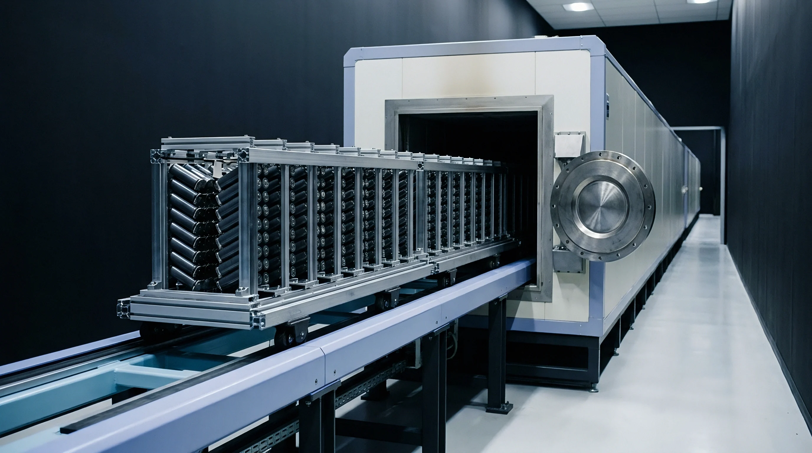
Thermal management in compact enclosures dictates both operating life and safety margins. Cylindrical cells generate heat through ohmic resistance and electrochemical reactions. Because low-volume packs are often squeezed into tight envelopes, adjacent cells couple thermally.
Running cells above forty-five degrees Celsius accelerates breakdown of the solid electrolyte interphase, causing rapid capacity loss.

Radial and Axial Heat Dissipation
Heat inside cylindrical steel cans travels mostly along the longitudinal casing rather than out through the radial plastic sleeve. The steel casing conducts heat efficiently to both positive and negative terminals, whereas radial thermal conductivity through the jelly-roll layers is an order of magnitude lower than axial conduction. Busbars attached to the terminals double as thermal paths, carrying away heat along with electrical current toward external cooling surfaces.
When an overcharged or compromised cell enters thermal runaway, its top vent ruptures to release hot gases and particulate matter. Blocking these vents with solid copper busbars forces exhaust downward, splitting the side walls. Module geometry must leave an unobstructed exhaust path directly above every safety valve.
Passive Management in Low Volume Build Constraints
Low-volume production rarely justifies the cost of custom cold plates or extruded cooling jackets. Integration teams rely instead on passive solutions, such as phase-change material matrices or elastomeric potting resins. Potting compounds displace air voids around cells, conducting heat to the enclosure while locking the assembly in place mechanically.
Thermal potting materials typically provide conductivities between 0.8 and 1.5 Watts per meter-Kelvin. Filled polyurethanes offer strong structural support but make rework difficult: once poured, compound captures the cells permanently, turning minor repairs into complete module replacements. Designers must weigh serviceability against thermal performance and structural strength.
Whether phase-change materials maintain long-term structural integrity in high-vibration environments remains a practical trade-off between thermal mass and overall pack weight.


Architecture
The structural frame defines a pack’s mechanical durability, electrical isolation, and field serviceability. Cylindrical cells require mechanical isolation to keep shock, vibration, and thermal expansion from stressing terminal welds. At the same time, the outer enclosure must maintain its Ingress Protection rating while holding internal modules firm under heavy impacts.

Mechanical Isolation and Structural Framing
Plastic carrier matrices position cells while preventing short circuits from vibration. Interlocking plastic holders allow flexible module layouts without upfront mold tooling costs, using polycarbonate or ABS blends for impact strength and dielectric protection. Maintaining at least 1.0 millimeter clearance between cells provides room for thermal expansion and cooling airflow while preventing chafing against the outer PVC sleeves.
Modular frames absorb external torsional loads so flexural stress does not reach welded interconnect tabs. In high-vibration applications, structural foam can replace plastic cell holders. Accessibility remains a key choice; using cold-melt assembly adhesives allows individual cell removal during prototype testing.
Under UN 38.3 test T.4, structural frame deflection greater than 0.5 millimeters causes weld stress failure at parallel interconnect taps.

Are Cell Fuses Required at Each Parallel Tap?
Wire-bond traces disconnect localized short circuits before thermal failure spreads across shared voltage nodes. In high-density parallel arrays, an internal separator failure in a single cell triggers heavy discharge current from adjacent cells, threatening module-wide thermal runaway. Micro-wire bonds double as cell-level fuses, vaporizing when current exceeds safe limits.
When using spot-welded nickel tabs, designers integrate narrow neck geometries into the stamped metal to act as fuses. Sizing the fuse neck depends on balancing peak operating discharge against short-circuit isolation speed. These stamped busbar features add minimal unit cost while guarding against catastrophic failures.
- Busbar Clearance Margin A minimum three-millimeter air gap prevents arc-over between adjacent series groups in humid conditions.
- Vibration Damping Shore Hardness Elastomeric potting materials require a Shore A hardness between forty and sixty to damp mechanical shock.
- Flame Retardancy Standard Plastic carriers must carry a UL 94 V-0 rating to retard flame spread during cell failures.
IEC 62133 clause 5.6 requires structural insulation barriers between parallel cell connections to prevent cascading failure, expanding the design focus from electrical contact to fire-retardant physical containment.

Economics
Economics in low-volume pack builds depend heavily on tooling choices, compliance testing, and warranty boundaries. Non-Recurring Engineering costs make up a large share of landed unit cost when spread over small volumes, meaning early architectural choices directly govern margins and certification overhead.

Tooling Amortization and Carrier Selection
Custom injection tooling for multi-cell plastic trays can cost tens of thousands of dollars upfront, stretching small project budgets. Standard interlocking matrices eliminate toolmaking costs, allowing immediate prototyping and quick layout changes.
Comparing 3D printing, CNC sheet milling, and injection molding highlights distinct financial break-even points. Machined polycarbonate plates work well for early prototype builds but grow expensive past two hundred units. For volumes under one thousand units per year, interlocking off-the-shelf holders offer the most practical compromise.
| Carrier Architecture | Upfront NRE ($) | Unit Cost at 100 Packs ($) | Unit Cost at 1,000 Packs ($) | Unit Cost at 5,000 Packs ($) |
|---|---|---|---|---|
| Custom Injection Molded Frame | 45,000 | 468.00 | 63.00 | 27.00 |
| Modular Interlocking Matrices | 0 | 34.00 | 31.50 | 29.00 |
| CNC Machined Polycarbonate Sheet | 1,200 | 142.00 | 88.00 | 76.00 |

Compliance Testing Expense and Certification Ownership
Shipping lithium-ion battery packs requires UN 38.3 transport safety certification, which involves eight mandatory environmental, mechanical, and electrical tests at an accredited lab. For low-volume builds, testing typically runs between $12,000 and $22,000 depending on pack size and testing lab. Because structural or electrical changes require re-testing, freezing the design early is essential.
Tooling investment for custom cell carriers breaks even when production volumes cross the threshold where assembly time savings offset initial mold fabrication.
Establishing clear warranty terms protects integration teams from both upstream cell defects and field abuse. BMS firmware sets hard limits for over-discharge, charge temperature, and cell balancing. Contracts must cleanly delineate distributor responsibility, pack assembly liability, and operating limits ~ specifically stating maximum discharge rates, ambient temperature bounds, and charge profiles.
Combining stock modular holders with standard nickel strip geometries keeps unit costs lower than custom injection tooling until production volumes reach the point where dedicated molds pay off.