Cylindrical and Prismatic Cell Architecture Selection Guidelines
Choosing between cylindrical and prismatic cell formats demands balancing tooling capital, thermal conduction interfaces, and structural face pressure limits.

Geometry
The choice of structural envelope dictates both mechanical density and module enclosure footprint. Small-format round cans establish high intrinsic structural resistance to internal gas pressures through cylindrical geometry. Canister walls made of nickel-plated steel operating at 0.15 mm to 0.30 mm thickness prevent radial deformation without requiring external clamping hardware.
Rectangular aluminum casings use wall thicknesses between 0.8 mm and 1.5 mm, relying on internal structural ties or external module compression plates to prevent bulging under pressure.

Mechanical Envelope and Volumetric Stacking
Cylindrical cans exhibit inherent structural rigidity from circular cross-sections, allowing thin steel walls down to 0.15 mm without outer support. Packing round cylinders into rectangular spaces creates unalterable voids between cells. The theoretical maximum volumetric packing limit for uniform cylinders in a hexagonal close-packed arrangement reaches 90.69 percent, while practical pack-level arrangements achieve between 65 percent and 78 percent once cooling channels, cell holders, and busbar clearances are accounted for, with tolerances accumulating across the module.
Large rectangular casings achieve pack-level volumetric packing efficiencies between 75 percent and 88 percent. The elimination of interstitial voids allows prismatic cells to lay flush against planar cold plates, maximizing usable enclosure volume. Prismatic shell tolerances, however, present complex stack-up challenges across long cell strings.
Dimensional variations across the width dimension of a VDA-standard prismatic cell (typically +/- 0.5 mm on a 148 mm dimension) accumulate rapidly across a 16-cell module, resulting in total module length variations of up to +/- 8.0 mm unless tolerance absorption pads are interleaved.
| Form Factor Designation | Nominal Dimensions (mm) | Shell Material & Thickness (mm) | Volumetric Density Range (Wh/L) | Maximum Cell-Level Swelling Allowance |
|---|---|---|---|---|
| 18650 Cylindrical | 18.3 x 65.1 | Nickel-Plated Steel (0.18 – 0.22) | 650 – 730 | Zero outer diameter expansion |
| 21700 Cylindrical | 21.3 x 70.3 | Nickel-Plated Steel (0.20 – 0.25) | 700 – 770 | Zero outer diameter expansion |
| 4680 Cylindrical | 46.0 x 80.0 | Nickel-Plated Steel (0.50 – 0.60) | 680 – 750 | Zero outer diameter expansion |
| VDA Prismatic Slim | 148.0 x 26.5 x 91.0 | Aluminium Alloy 3003 (0.80 – 1.00) | 550 – 640 | 8 percent thickness increase over life |
| VDA Prismatic Thick | 148.0 x 54.0 x 91.0 | Aluminium Alloy 3003 (1.00 – 1.20) | 600 – 680 | 10 percent thickness increase over life |

Electrode Architecture and Internal Current Paths
Jellyroll windings generate high internal current concentrations at the single tab connection point, elevating local ohmic resistance. Cylindrical cells historically utilized a single copper anode tab and single aluminium cathode tab spot-welded to the top cap and bottom header. This architecture creates non-uniform current distribution along the spiral length of the electrode roll, generating localized thermal hot spots during charge and discharge pulses above 3C continuous rates.
Tabless cylindrical designs resolve path resistance by continuous laser welding of the uncoated copper and aluminium foil edges directly to current collector plates at the can extremities. This shortens the electron travel distance from the full length of the electrode strip (often exceeding 1,000 mm in a 21700 cell) down to the axial height of the cell (70 mm to 80 mm). Internal DC resistance drops from 18-22 milliohms in standard tabbed 21700 cells down to 2-3 milliohms in tabless 4680 configurations.
Stacked electrode architectures in prismatic cells utilize discrete cathode, separator, and anode sheets laminated together. Every individual electrode plate possesses its own current collector tab, which are gathered and ultrasonically welded into a consolidated terminal block. This parallel connection path minimizes internal ohmic drop, distributing current uniformly across the planform area of the electrode sheet and reducing localized current density peaks that trigger lithium plating.
Integrating these configurations into structural pack enclosures introduces distinct mechanical failure risks that must be accounted for during early design phases.
- Interfacial Shearing at Cell Terminals occurs when module flexure under chassis twist forces differential movement between rigid busbars and floating cell tops.
- Pouch and Casing Breach via Burr Penetration results from uncleaned laser cut edges on internal current collector tabs piercing separator layers under vibration.
- Structural Delamination of Cold Plate Bonds develops when differential thermal expansion between steel cylinders and aluminium heat exchangers breaks rigid adhesive joints.
- Compressive Creep of Inter-Cell Insulation leads to loss of pre-load tension in module tie rods, allowing prismatic cells to shift during mechanical shock events.
Volumetric capacity gains on paper compensate for assembly yield losses during initial pack automation trials.


Heat
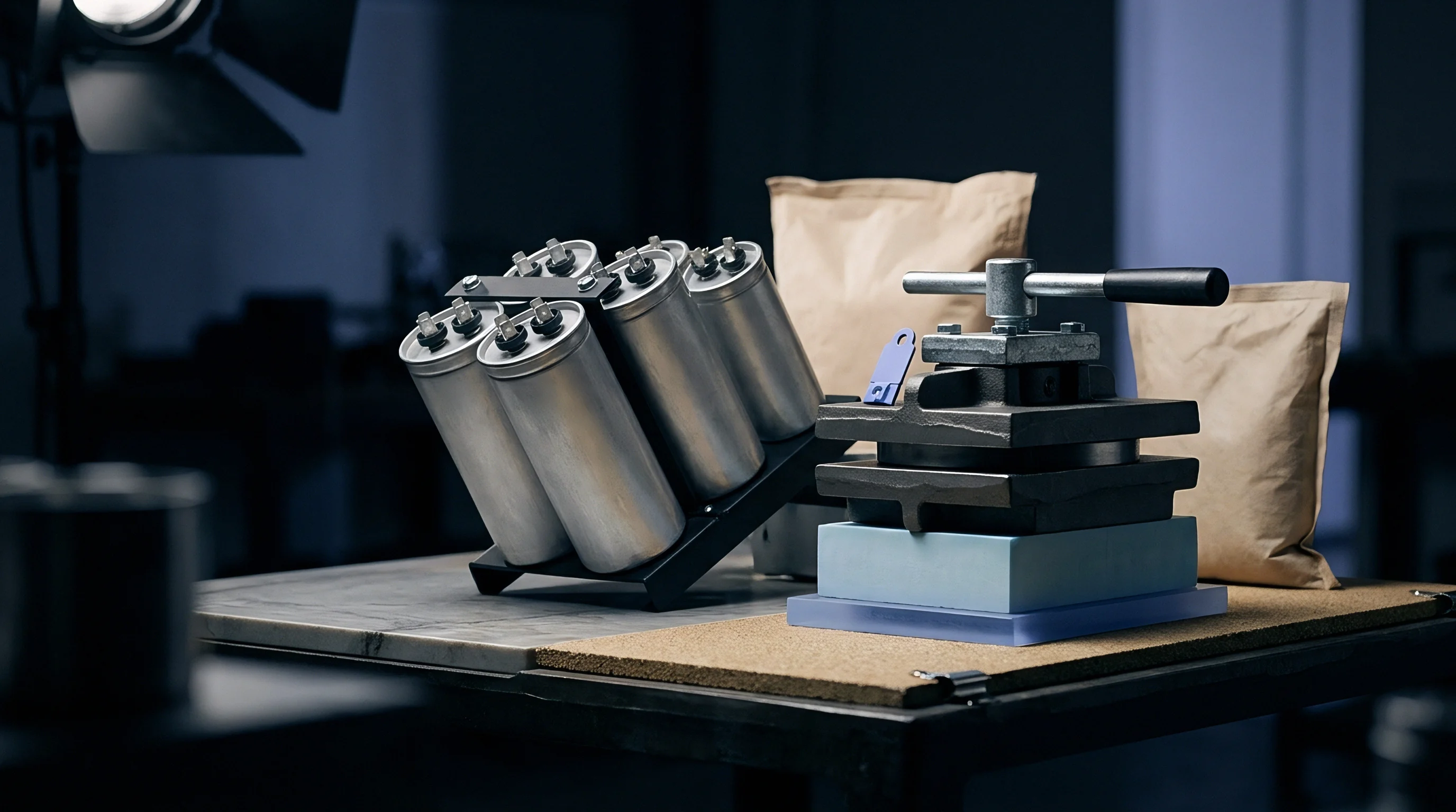
Thermal dissipation paths vary fundamentally between round steel cans and rectangular aluminium casings. Cylindrical cells conduct thermal energy primarily through the radial axis, facing high internal resistance across laminated electrode layers. The radial thermal conductivity of a wound jellyroll typically ranges from 0.5 to 1.5 W/m K, whereas axial conductivity along the metallic foil layers reaches 20 to 30 W/m K, even as internal gas pressure acts against casing walls.
Thermal Conduction Anisotropy across Form Factors
Prismatic casings offer expansive, planar surfaces that align directly with cold plates, achieving interface contact resistance below 0.15 cm² K/W. Heat generated within stacked prismatic electrodes travels short distances across the thickness axis directly to the wide aluminium sidewalls. Cooling plates positioned beneath or alongside prismatic modules transfer heat effectively across large surface areas, keeping maximum temperature differentials across the cell face under 3 degrees Celsius during 2C continuous discharge cycles.
Base cooling of cylindrical cells forces thermal energy to travel axially along internal copper current collectors to the bottom of the can. While axial thermal conductivity is high, the contact surface area at the cell base is small (approximately 346 mm² for a 21700 cell). Side cooling using snake-type extruded aluminium cold tubes wrapped around cell perimeter walls expands the contact area, but thermal energy must pass through multiple insulating layers, including internal separator sheets, jellyroll voids, thin steel walls, and exterior electrical insulation sleeves.
Heat transfer through silicone gap fillers degrades by up to 40 percent when interfacial pressure drops below 150 kPa under dynamic chassis vibration.

Active Surface Area to Volume Ratios
Small format cans provide approximately 250 square millimetres of external area per cubic centimetre of active volume. High surface-to-volume ratios enable passive thermal dispersion in low-rate applications. As cell diameter increases to 46 mm, the surface-to-volume ratio decreases by more than half, forcing active liquid cooling integration directly into the terminal contacts or using direct immersion cooling with dielectric fluids.
Applying thermal interface materials requires precise sequencing to prevent air entrapment and maintain low contact resistance across automated production lines.
- Dispense high-viscosity two-part polyurethane or silicone thermal gap filler onto the cold plate using automated metering pumps.
- Inspect filler bead volume and placement pattern using 3D laser profiling vision systems to verify missing bead defects.
- Lower cell assembly or module frame into the wet filler at controlled velocity to prevent air pocket entrapment.
- Apply continuous compression force until mechanical stops engage, verifying a wet-out thickness between 0.3 mm and 0.8 mm.
- Cure the assembly at ambient or elevated temperatures according to the resin chemistry specification before applying electrical testing loads.
Thermal runaway propagation exhibits distinct behavior across form factors. Cylindrical cells isolate single-cell failure events effectively when spaced with adequate interstitial distance or potting materials. The thermal mass of an individual 21700 cell (approximately 70 grams) releases around 150 to 250 kJ of energy during runaway.
Prismatic cells contain substantially larger energy quantities per unit (a 100 Ah LFP cell contains over 320 Wh of stored energy), releasing up to 2.5 MJ of thermal energy during catastrophic vent events. Propagation prevention in prismatic packs demands aerogel insulation panels or inorganic mica sheets between adjacent cell faces capable of resisting continuous temperatures exceeding 1,000 degrees Celsius.
Selecting an inappropriate thermal path forces unexpected derating during fast charge, cutting usable power output by thirty percent.


Joint
Electrical interconnects handle dynamic mechanical shock while maintaining micro-ohm interfacial resistance over full operational lifespans. Joining high-power busbars to cell terminals involves complex metallurgy, thermal dissipation constraints, and strict process control limits. Laser welding, ultrasonic wedge bonding, and mechanical fastening each present distinct joint characteristics depending on terminal material composition and geometry, where thermal sinks can draw current away from the weld zone.
Interconnect Metallurgy and Joining Physics
Laser welding copper busbars to aluminium terminals creates brittle intermetallic compounds when melt pool temperatures breach equilibrium thresholds. The formation of copper-aluminium intermetallic phases, such as CuAl2 and Cu9Al4, increases joint electrical resistance and creates microscopic stress cracks under thermal cycling. Fiber lasers operating at green (515 nm) or blue (450 nm) wavelengths overcome the low infrared absorption of bare copper (under 5 percent absorption at 1,064 nm wavelength compared to over 60 percent at 450 nm), producing stable weld penetrations between 0.3 mm and 0.8 mm without excessive heat input.
Ultrasonic wedge bonding uses high-frequency mechanical friction (typically 20 kHz to 60 kHz) to break surface oxide layers and create solid-state atomic bonds. This cold-joining process eliminates thermal stress and intermetallic embrittlement, making it suitable for bonding thin aluminium ribbons (0.3 mm to 0.5 mm thick) onto nickel-plated cylindrical cell tops. Ultrasonic bonds exhibit lower ultimate shear strength than laser welds, requiring multiple parallel bonding wires per cell to meet current density and mechanical pull-strength criteria.
| Joining Method | Terminal Material Pair | Contact Resistance (micro-ohms) | Shear Pull Strength (N) | Heat-Affected Zone Depth (mm) |
|---|---|---|---|---|
| Laser Weld (Infrared 1064nm) | Aluminium to Aluminium | 8 – 15 | 450 – 650 | 0.40 – 0.80 |
| Laser Weld (Blue 450nm) | Copper to Aluminium | 5 – 10 | 600 – 850 | 0.15 – 0.35 |
| Ultrasonic Wedge Bond | Aluminium Wire to Nickel Plate | 25 – 40 | 35 – 60 | Zero (Solid-state) |
| Resistance Spot Weld | Nickel Strip to Steel Can | 40 – 80 | 120 – 180 | 0.20 – 0.50 |
| Bolted Threaded Fastener | Copper Busbar to M6 Terminal | 15 – 30 | Mechanical Clamping | Zero (Mechanical) |

Vibration Resistance and Weld Strain Rates
Dynamic loading along module axes induces high fatigue stress in cantilevered copper busbar ribbons. Small cylindrical pack assemblies utilize flexible, ocean-wave shaped copper or aluminium busbars to decouple individual cell movements caused by enclosure vibration. In rigid prismatic modules, cell swelling exerts direct axial force on rigid busbars, causing stress concentration at the weld heel.
Quality management provisions in ISO 14555 require non-destructive shear testing on 100 percent of pilot-line busbar welds prior to high-voltage isolation checks.
Vibration fatigue testing per ISO 16750-3 demonstrates that solid, un-relieved busbars spanning across prismatic terminals suffer fatigue failure at the weld seam boundary within 200 hours of random vibration exposure between 10 Hz and 2,000 Hz. Flexible laminated busbars, composed of multiple ultra-thin (0.1 mm) copper diffusion-welded sheets at the connection pads, absorb multi-axis displacement without transferring bending moments to the cell terminal seal.
Aluminium surfaces require thorough cleaning to eliminate oxides before joining.
Whether micro-fretting corrosion at mechanically bolted busbar joints can be reliably predicted without multi-thousand-hour cyclic thermal testing remains unresolved across high-vibration heavy equipment integrations.


Scale
Capital investment decisions shift drastically when moving from flexible automated cylindrical lines to dedicated prismatic assembly cells. Manufacturing facility footprint, non-recurring engineering costs for custom tooling, and automated assembly cycle times determine the break-even production volume between cell form factors, where custom dies require volume to justify NRE expenses.
Which Integration Path Minimizes Capital Risk?
Module-free pack designs demand high initial non-recurring engineering fees for cell-to-body extrusion dies and specialized structural adhesives. Standardized cylindrical cells (18650 and 21700) benefit from massive existing commodity production lines, offering low off-the-shelf cell costs ($80/kWh to $100/kWh at tier-one factory level). Automated pack assembly equipment for cylindrical formats, however, carries high capital costs due to the vast number of individual connections required.
A 80 kWh pack using 21700 cells contains over 4,000 individual cells, requiring 8,000 discrete welds per pack.
Prismatic cell architectures reduce total cell count dramatically. An equivalent 80 kWh pack built with 100 Ah prismatic cells requires approximately 250 cells, cutting the number of pick-and-place operations, terminal inspection points, and weld instances by 94 percent. High-capacity prismatic cells ($70/kWh to $90/kWh) lower pack integration tooling expenses, but demand custom extrusion dies ($150,000 to $300,000 per profile) and specialized module stamping fixtures that are difficult to repurpose when cell dimensions update.
Tooling amortization costs drop below five dollars per kilowatt-hour only when production volumes exceed fifty thousand pack units per year on dedicated automation lines.

Line Speed and Equipment Amortization Limits
Automated pick-and-place robotics achieve cycle times under 0.8 seconds per cell when loading cylindrical formats into structural honeycombs. High-speed laser welding systems process up to 30 joints per second using dynamic galvo-scanner heads, though line yield drops during initial ramp-up.
Evaluating non-recurring capital allocation requires structured criteria based on annual volume targets and design flexibility requirements.
- Total Initial Tooling Capital Expenditure must account for custom cell holders, stamping dies, welding nests, and automated vision inspection calibration targets.
- Flexibility for Chemistry and Dimension Updates evaluates whether production lines accommodate height or diameter changes without replacing primary transfer automation.
- Scrap Rate Amortization Burden calculates the financial impact of discarding an entire multi-cell module versus isolating a single rejected cell during assembly.
- In-Line Process Control Integrity verifies high-speed inspection capabilities including 3D laser weld seam profiling, thermal imaging, and high-voltage isolation resistance testing.
High automated throughput reduces direct labor costs to less than 2 percent of total pack cost, shifting operational focus entirely to material yield management and incoming cell grade consistency.
An explicit contract clause capping tool modification costs at five percent of total NRE shifts process redevelopment expenses back to the equipment supplier when tolerance stack-ups fail initial gauge studies.


Fade
Capacity retention loss over extended thermal cycling reflects combined chemical side-reactions and mechanical degradation. Electro-mechanical breathing during intercalation cycles creates localized stress distributions inside cell enclosures. In rigid steel cylinders, radial hoop stress keeps electrode layers tightly bound, limiting physical delamination.
In prismatic casings, planar faces bulge outwards under internal pressure, altering interfacial contact between electrode sheets, while cold charging accelerates degradation.

Mechanical Breathing and Interfacial Pressure Evolution
Prismatic lithium iron phosphate cells expand up to 4 percent in thickness across 3,000 deep discharge cycles. This volumetric growth stems from solid electrolyte interphase buildup, graphite lattice expansion during lithiation, and gas accumulation from electrolyte breakdown. Without external structural restraint, expansion creates micro-gaps between electrode sheets, increasing internal cell impedance by over 50 percent and accelerating localized lithium plating.
Engineers apply controlled compression pre-loads (typically 0.3 MPa to 1.0 MPa) using spring-loaded end plates or compressed foam pads within module frames. As the cell ages and expands, internal pressure rises. If the restraint system is overly rigid, face pressure exceeds 3.0 MPa, crushing the micro-porous polymer separator, restricting ionic transport, and inducing rapid capacity fade as creep alters interface pressure.
Lithium plating issues remain a primary driver of cell rejection during lifecycle testing.
Uniform face compression at 0.5 MPa extends cycle life by 35 percent compared to unconstrained prismatic cell operation under identical thermal profiles.

Degradation Acceleration under Non-Uniform Pressure
Unbalanced mechanical restraint leads to localized electrode lithium plating during aggressive cold-temperature charging. When module compression end plates flex under load, pressure concentrates at the edges of the prismatic cell face while the center expands freely. Low-pressure regions experience increased distance between cathode and anode plates, elevating local resistance and diverting current flow toward the high-pressure peripheral zones.
A worked example highlights the mechanical stress difference between cell architectures under long-term cycling. Assume a 100 Ah LFP prismatic cell measuring 148 mm in width and 91 mm in height subjected to 2,000 cycles. The active planform area equals 13,468 mm².
An unconstrained cell expands in thickness by 2.5 mm. Restraining this expansion to a maximum allowable growth of 0.5 mm using rigid spring-loaded endplates generates an internal swelling force of approximately 12 kN at end-of-life. The resulting face pressure reaches 0.89 MPa, remaining within safe operational limits.
In contrast, an equivalent volume pack constructed with 21700 cylindrical steel cells experiences zero outer diameter growth due to the 0.22 mm thick steel canister retaining radial expansion internally at hoop stresses exceeding 45 MPa, completely eliminating the need for module compression hardware.
Thermal runaway propagates laterally across adjacent cells in a module.
Cell restraint systems built to maintain uniform face pressure always outlast rigid enclosures that ignore swelling forces.


Seam
Commercial boundaries between cell suppliers, pack integrators, and original equipment manufacturers define where legal liability rests. Specifying cell form factor sets physical integration rules while fixing compliance ownership and warranty liability split points.

Compliance Responsibility Boundaries
International transport testing under UN 38.3 mandates individual cell qualification prior to sub-assembly integration. Cell manufacturers deliver certified components accompanied by UN 38.3 test summary reports (covering altitude simulation, thermal testing, vibration, shock, external short circuit, impact/crush, overcharge, and forced discharge). Modifying cell geometry, attaching custom tabs, or applying external insulation sleeves voids the original cell-level certification, transferring re-testing liabilities to the pack assembler.
Pack-level certification under UL 1973 or IEC 62619 demands system-level evaluation. When using cylindrical cells, proving thermal runaway non-propagation often requires extensive potting or specialized directional venting design within the module. Prismatic implementations rely on cell-level pressure relief vents designed to exhaust gases at pre-determined thresholds (typically 0.2 MPa to 0.6 MPa).
Integrators must ensure the pack enclosure contains exhaust gas manifolds that route toxic and flammable effluents safely outside the vehicle or equipment compartment without rupturing structural walls, as sourcing rules explicitly fix responsibility.
| Evaluation Metric | Small-Format Cylindrical (21700) | Large-Format Cylindrical (4680) | Prismatic LFP / NMC |
|---|---|---|---|
| Tooling NRE Capital Risk | Low ($20,000 – $50,000) | Medium ($100,000 – $250,000) | High ($200,000 – $500,000) |
| Thermal Interface Complexity | High (Snake tubes / Potting) | High (Immersion / Base cold plate) | Low (Planar bottom cold plate) |
| Mechanical Restraint Need | Zero (Self-retained steel can) | Zero (Self-retained steel can) | High (Pre-load endplates required) |
| BMS Sensing Wire Count | Low (Parallel group sensing) | Low (Parallel group sensing) | High (Individual series cell sensing) |
| Warranty Defect Isolation | Difficult (Multi-cell groups) | Moderate (Fewer cells per group) | Direct (Single-cell isolation) |

Commercial Risk Seams in Pack Assembly
Warranty allocations frequently fracture when field failure causes remain ambiguous between BMS software faults and cell manufacturing flaws, where warranty obligations split along physical interfaces.
Clear contractual demarcation requires precise documentation attached to incoming shipment lots and final pack handoff dossiers.
- Cell Specification Sheet Limits must define upper and lower limits for operational voltage, continuous discharge current, peak pulse duration, and temperature envelopes.
- Incoming Quality Inspection Dossier contains open-circuit voltage, internal AC impedance at 1 kHz, and dimensional gauge verification records for every batch lot.
- Traceability Record Mapping connects individual cell serial numbers to specific module positions, weld machine parameters, and line operator IDs.
- Boundary Interface Agreement defines explicit ownership for thermal gap filler application, busbar weld integrity, and BMS firmware parameter programming.
The final landed cost reflects both the physical hardware and the explicit allocation of technical risk between cell vendor, pack manufacturer, and system integrator.