Solid State Module Spring Plate Preload Calculation Rules
Solid state module spring plates calculate stiffness to hold pressure within cell operating limits across state of charge expansion and manufacturing tolerances.
Stack
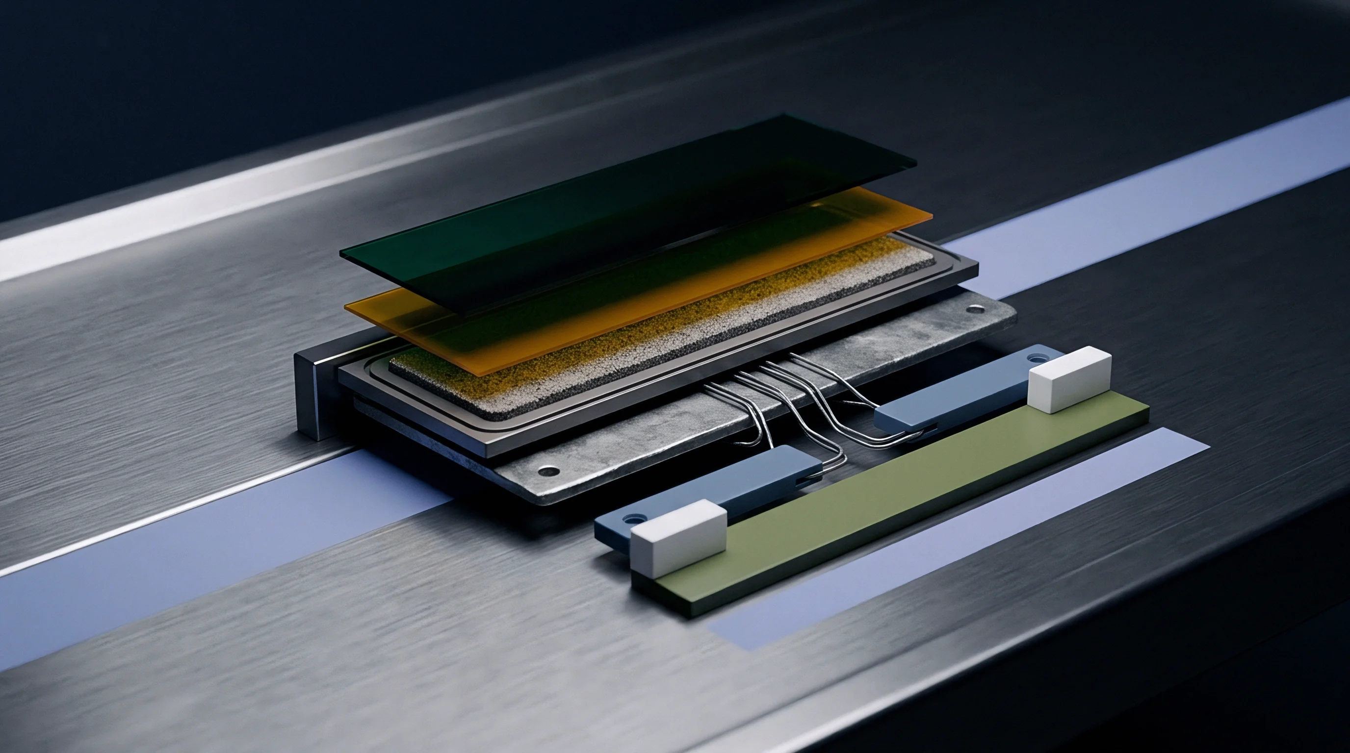
Unlike liquid batteries that accommodate volume changes through fluid flow, solid-state designs depend entirely on maintaining tight solid-solid contact across electrolyte interfaces during charge and discharge. During discharge, stripping lithium from the anode forms microscopic voids if clamping pressure falls below a critical threshold. Too much pressure, on the other hand, cracks ceramic separators and forces lithium plating along solid electrolyte grain boundaries.
Interfacial Void Formation and Contact Pressure
Maintaining continuous ionic transport requires constant physical contact between the electrolyte separator and the lithium metal anode as the anode expands and contracts during cycling. Sulfide-based electrolytes generally need 1.0 MPa to 5.0 MPa of stack pressure to preserve these contact paths. Oxide ceramic separators tolerate higher overall compressive loads but fracture easily under local stress concentration due to low strain tolerance, while composite and polymer electrolytes operate at lower pressures between 0.2 MPa and 1.5 MPa.
Without steady mechanical contact, interfacial ionic resistance rises rapidly.
As lithium leaves the anode during discharge, sub-surface voids collapse only if external force is sufficient.
- Determine the baseline stripping voltage drop threshold at zero percent state of charge under maximum continuous discharge current.
- Measure interfacial impedance across a pressure sweep from 0.1 MPa to 8.0 MPa using electrochemical impedance spectroscopy.
- Identify the lower critical pressure where charge-transfer resistance increases by more than fifteen percent.
- Establish the upper mechanical compressive limit where separator thickness degrades by more than two percent.
- Define the nominal operating band between the lower impedance boundary and upper structural yield limit.
Sulfide solid electrolytes require higher baseline clamping force than polymer composites to prevent anodic void accumulation during discharge.
Establishing these pressure boundaries is essential for each electrolyte formulation, as dropping below the minimum limit causes internal resistance to spike during high-rate discharge pulses.
| Chemistry Class | Separator Material | Min Operational Pressure (MPa) | Max Allowable Pressure (MPa) | Thickness Expansion per 100% SoC Swell (%) |
|---|---|---|---|---|
| Sulfide-based | Li6PS5Cl (Argyrodite) | 1.0 | 5.0 | 4.5 to 8.0 |
| Oxide ceramic | Li7La3Zr2O12 (LLZO) | 0.5 | 3.0 | 2.0 to 5.0 |
| Halide-based | Li3InCl6 | 1.5 | 6.0 | 3.5 to 7.0 |
| Polymer composite | PEO-LLZO hybrid | 0.2 | 1.5 | 1.5 to 4.0 |
Inadequate or uneven initial loading causes rapid capacity loss from micro-delamination, local hot spots, and early short circuits during early cycling.
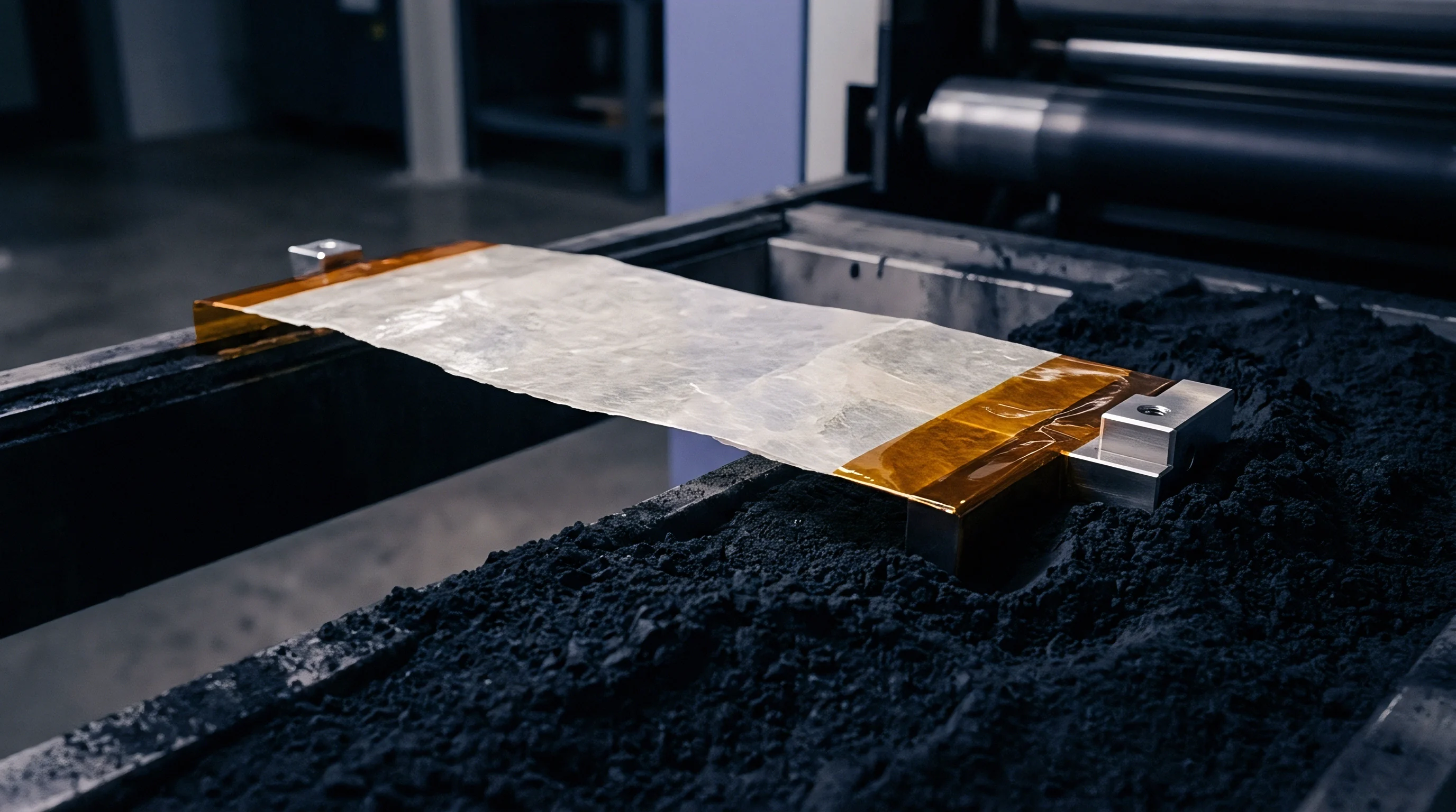
Deflection
Spring plates turn compressive displacement inside a module housing into a controlled clamping force across the cell stack. Selecting the right spring architecture determines how well the assembly absorbs swelling during charging without exceeding safe pressure limits. Wave springs, Belleville washer arrays, and microcellular polyurethane pads are the main compliance elements used in these packs.
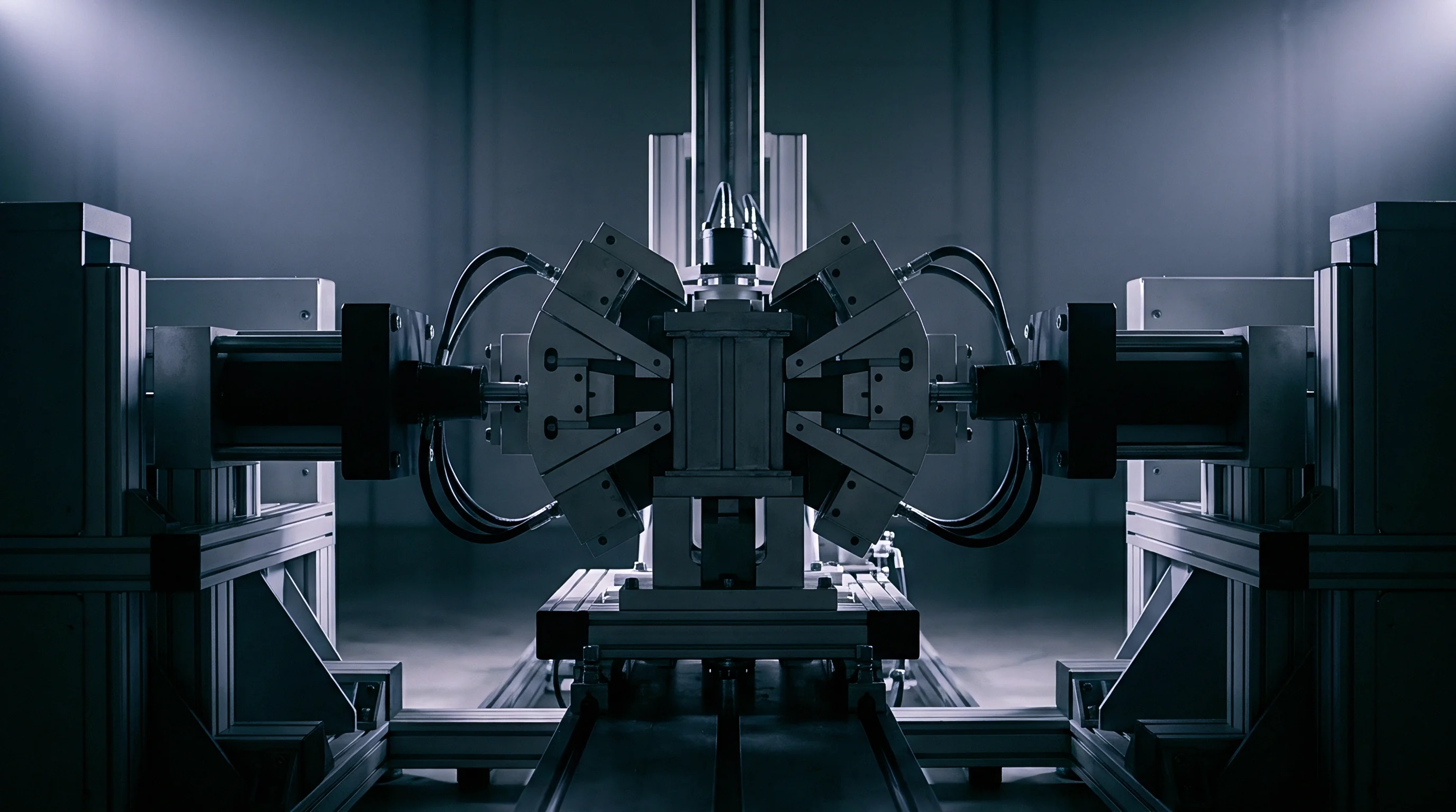
Spring Element Mechanics and Load Uniformity
Flat structural plates bend under point loads or edge constraints, creating uneven pressure across the cell surface. Plate stiffness can be modeled using Euler-Bernoulli beam flexure adjusted for uniform area loads, where flexural rigidity scales with the material’s elastic modulus and the cube of plate thickness. Stiffer plates keep the module compact but produce sharp pressure spikes as cells expand, while more flexible springs yield flatter force-deflection curves at the cost of a larger overall footprint.
Local bending across the plate reduces edge clamping force.
Steel spring elements maintain a nearly linear force response over their active travel range.
A pressure non-uniformity exceeding twelve percent across the active cell surface accelerates localized lithium dendrite growth at high C-rates.
Pressure-sensitive films map stress distribution across cell surfaces during assembly. Profiling spring plates with variable thickness helps offset endplate deflection, keeping compression uniform throughout the cell stack.
| Spring Architecture | Material Grade | Force-Deflection Linearity | Volumetric Efficiency | Thermal Stability Range (°C) |
|---|---|---|---|---|
| Nested Belleville Washers | 17-7 PH Stainless Steel | Non-linear regressive | Moderate | -40 to +150 |
| Multi-Wave Spring Plate | 301 Stainless Steel | Linear active zone | High | -40 to +120 |
| Microcellular Polyurethane | High-density PU foam | Progressive non-linear | Very High | -30 to +80 |
| Leaf Spring Array | 51CrV4 Spring Steel | Linear | Low | -40 to +150 |
Premature cell swelling often stems from structural housing deflection rather than unannounced batch variations in separator porosity.

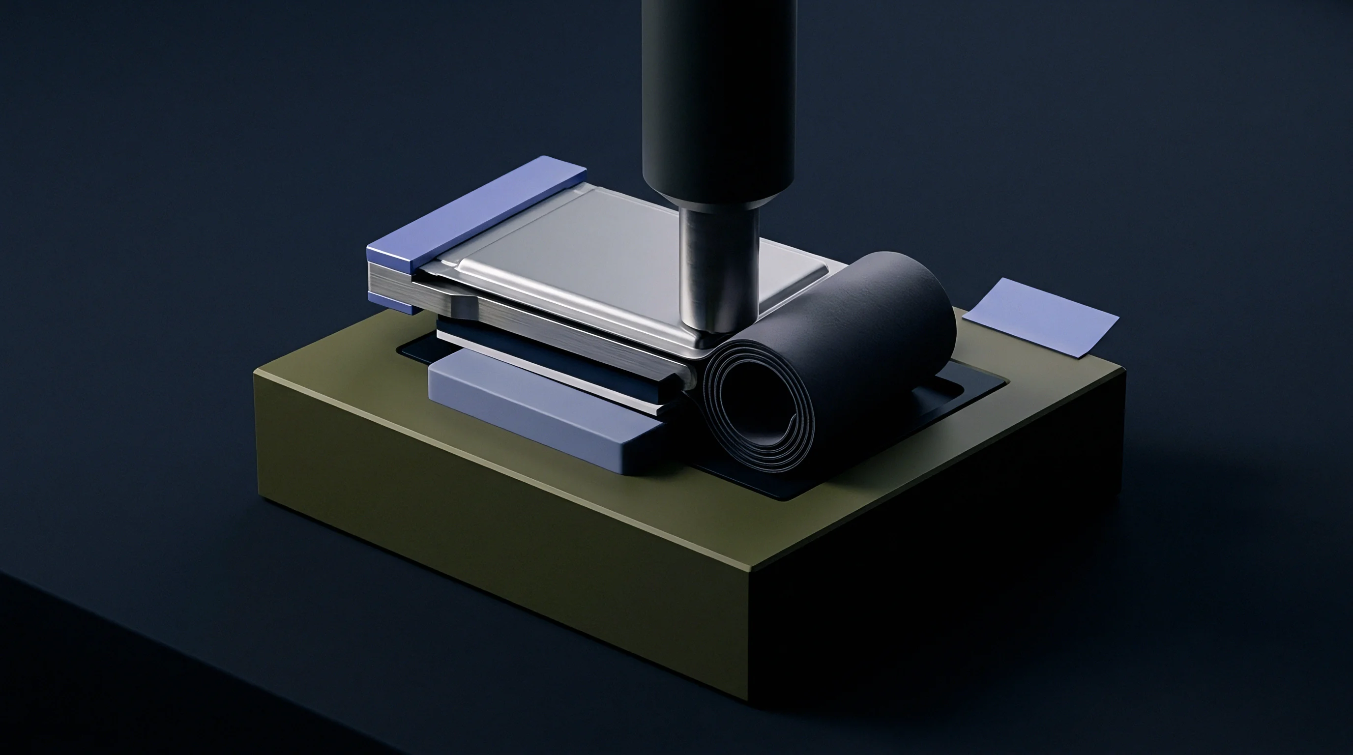
Expansion
Reversible lithium deposition during charging causes pouch cells to expand along their thickness axis. In pure lithium anode designs, plating adds roughly 14.7 micrometers of thickness per 10 Ah of capacity. Module spring plates must absorb this breathing, staying above minimum required pressure at zero percent state of charge while keeping below maximum pressure at full charge.

Which Mechanical Tolerances Drive Peak Stack Pressure Spikes?
Dimensional variations in housing endplates, spring thickness, and cell manufacturing accumulate along the stack axis. With a typical cell thickness tolerance of plus or minus 0.05 mm, a twelve-cell stack inherits up to 0.60 mm of height variance from manufacturing alone. Thermal expansion during high-power operation adds further displacement, making total stack growth the sum of electrochemical expansion, thermal expansion, and tolerance stack-up.
Dynamic cell thickness changes directly reflect the state of charge.
Thermal expansion adds further mechanical displacement across the assembly.
Manufacturing thickness tolerances scale directly with cell count.
- Separator Crushing occurs when combined stack expansion drives compressive stress past the yield strength of the ceramic or polymer membrane, causing dielectric breakdown.
- Anodic Void Accumulation happens when spring relaxation drops clamping pressure below the level required for lithium diffusion during high-rate stripping.
- Housing Endplate Yielding occurs when dynamic pressure from thermal and electrochemical expansion exceeds fastener clamp load, permanently distorting the module frame.
- Busbar Shear Fatigue results from repeated cycling along the stack axis, stressing welded tab connections.
UN 38.3 vibration testing invalidates module certification if mechanical spring plates lose more than ten percent of specified nominal preload following sinusoidal sweep cycles.
Differing thermal expansion rates between steel tie-rods and aluminum housings alter clamping force as temperature changes. At elevated temperatures, aluminum expands faster than steel elements, reducing preload unless thermal compensation washers are built into the fastener stack.
ISO 12405-4 Section 6.3 requires recording pressure retention during combined mechanical shock and thermal cycling prior to final sign-off.

Arithmetic
Sizing a spring plate assembly requires balancing spring rate, displacement, and pressure limits across operating conditions. Walking through a 12-cell solid-state module illustrates how to calculate target stiffness and initial preload.
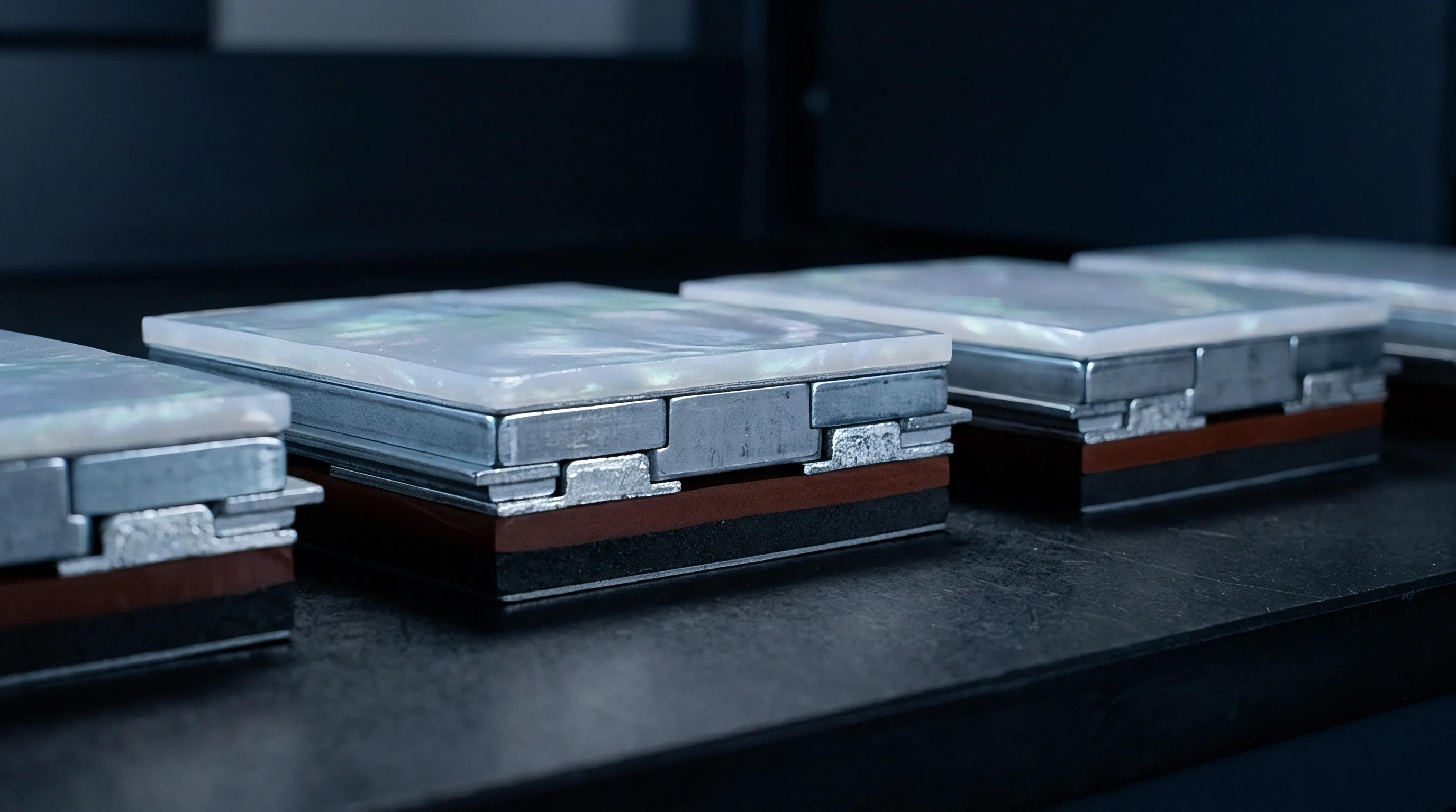
Preload Calculation Governing Equations
Modeling module forces relies on balancing spring stiffness against stack expansion. Dynamic pressure on the active cell area follows the standard force balance relation:
P(SoC, T) = k_spring * (X_initial + Delta_X_stack) / A_cell
Where A_cell is active contact area (m²), k_spring is effective spring plate stiffness (N/m), X_initial is initial spring pre-compression (m), and Delta_X_stack is dynamic stack displacement (m).
Spring rate selection must accommodate two distinct pressure limits.
Excessive compression damages solid electrolyte separator membranes.
Take a 12-cell series module using sulfide solid electrolyte pouch cells. Each cell has an active contact area of 0.015 square meters (150 mm by 100 mm) and a nominal discharged thickness of 8.00 mm with a manufacturing tolerance of plus or minus 0.05 mm. Lithium plating adds 25 micrometers (0.025 mm) of thickness per cell at full charge.
Housing stiffness is 50 kN/mm. Operating criteria dictate a minimum pressure of 1.0 MPa at 0% state of charge to prevent voiding and a maximum of 3.5 MPa at 100% state of charge to protect separator integrity.
Minimum allowable force at 0% state of charge is 1.0 MPa multiplied by 0.015 square meters, or 15,000 N (15.0 kN). At 100% state of charge, maximum force is 3.5 MPa multiplied by 0.015 square meters, giving 52,500 N (52.5 kN). The allowable force rise over a full charge cycle is 52.5 kN minus 15.0 kN, or 37.5 kN.
Total dynamic expansion across twelve cells equals 12 times 0.025 mm, or 0.300 mm (0.0003 m). Dividing allowable force rise by expansion gives a maximum combined system stiffness of 37.5 kN / 0.300 mm = 125.0 kN/mm. Accounting for a housing rigidity of 500 kN/mm yields a target spring plate stiffness of 166.7 kN/mm.
Initial spring pre-compression is minimum force divided by spring stiffness: 15.0 kN / 166.7 kN/mm gives 0.090 mm (90 micrometers).
Tolerance stack-up creates a significant practical challenge. A variance of plus or minus 0.05 mm per cell across twelve cells produces a cumulative stack tolerance of plus or minus 0.60 mm ~ twice the 0.300 mm expansion caused by charging. If a stack sits at the upper limit (+0.60 mm), a rigid 166.7 kN/mm spring plate adds 100.0 kN of unintended preload (166.7 kN/mm × 0.60 mm).
Starting force at 0% state of charge hits 115.0 kN (7.67 MPa), well above the maximum allowable cell pressure before the pack is even cycled.
- Selective Thickness Shimming bins cell stacks into 0.10 mm height increments during assembly, matching shim plates to measured stack height to neutralize tolerance variance.
- High-Travel Wave Springs reduce spring rate and extend pre-compression stroke to 3.0 mm, lowering pressure sensitivity to dimensional variations.
- Elastomeric Foam Compensation uses microcellular foam pads with non-linear stress-strain response to absorb stack variations at low initial modulus.
Stack tolerance stack-up dominates module preload variation more than chemical state-of-charge expansion.
| Tolerance Condition | Initial Deflection (mm) | Min SoC Pressure (MPa) | Max SoC Pressure (MPa) | Pressure Compliance Status |
|---|---|---|---|---|
| Nominal Stack (0.00 mm) | 0.090 | 1.00 | 3.50 | Compliant |
| Max Stack (+0.60 mm, Un-shimmed) | 0.690 | 7.67 | 10.17 | Failed (Over-pressure) |
| Min Stack (-0.60 mm, Un-shimmed) | -0.510 | 0.00 | 0.00 | Failed (Contact Loss) |
| Max Stack (+0.60 mm, 0.10 mm Shimmed) | 0.140 | 1.55 | 4.05 | Marginal Out-of-Spec |
| High-Travel Wave Spring (k = 15 kN/mm) | 1.000 | 1.00 | 1.30 | Fully Compliant |
Whether low-stiffness wave plate arrays can retain dimensional stability through hundreds of thousands of compression cycles remains an open question for long-life storage systems.
Relaxation
Spring elements and elastomeric pads undergo stress relaxation under sustained compression and thermal cycling. This loss of clamping force can drop pressure below minimum requirements late in pack life. Stainless steel wave plates hold tension well under thermal exposure, while elastomeric foam pads suffer progressive creep over years of operation.
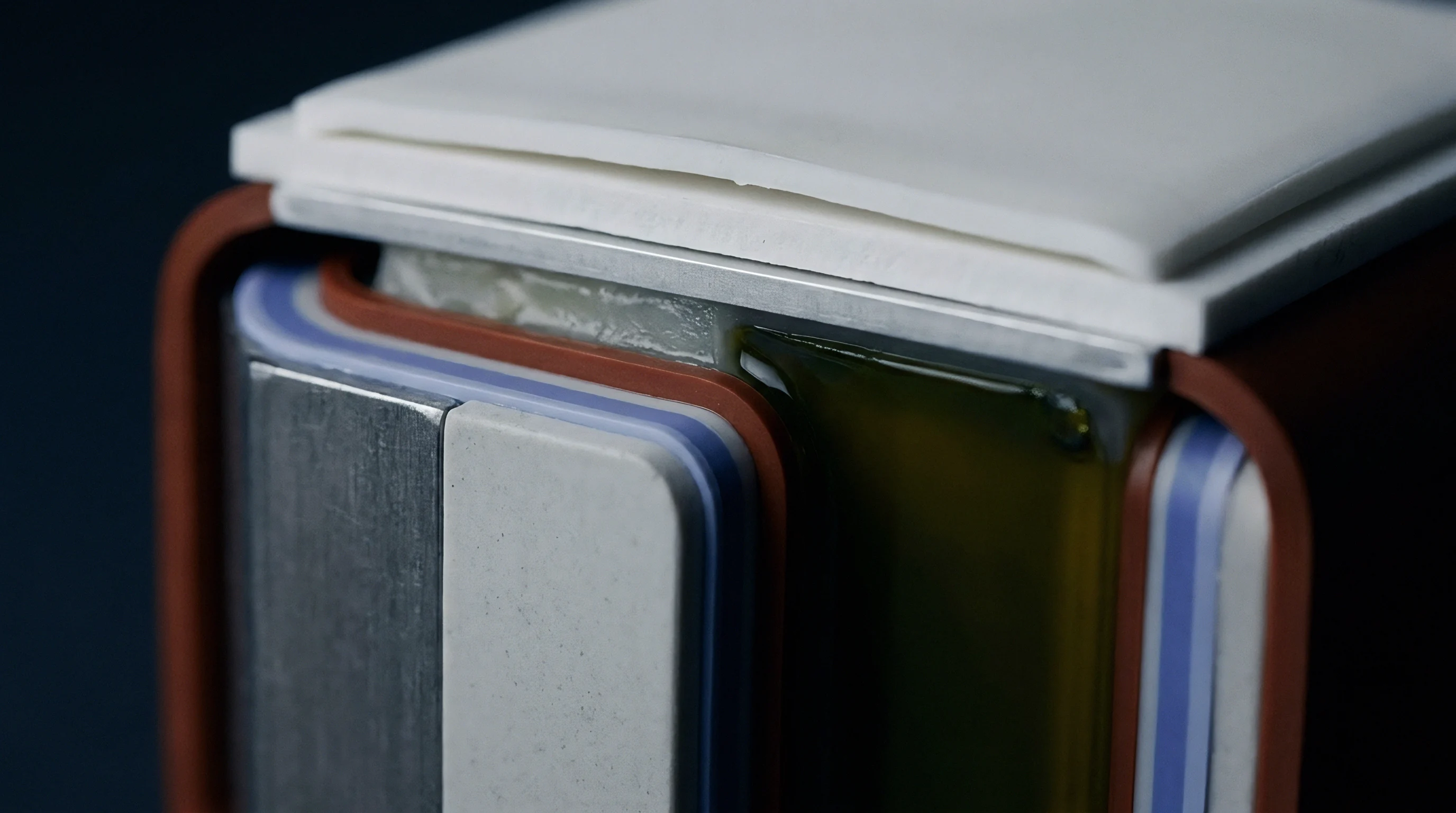
Long-Term Load Retention and Creep Kinetics
Polymer pads and spring steels lose load through entirely different mechanisms at elevated temperatures. High-density polyurethane foams relax viscoelastically, losing twenty to thirty-five percent of initial preload within 1,000 cycles between -30°C and +65°C. By contrast, precipitation-hardened 17-7 PH stainless steel spring plates retain over ninety-seven percent of preload under the same conditions.
Preload decay directly impairs long-term cell life.
Mechanical creep reduces structural clamping retention over time.
Dynamic load monitoring helps validate FEA deflection models.
Uniform pressure distribution inhibits lithium dendrite growth.
Stack thickness continues to fluctuate throughout electrical cycling.
Installing load cells in pilot production runs tracks real-time stress relaxation. Spring plate designs must include a relaxation safety margin in the initial preload, offsetting projected ten-year creep without over-stressing new cells during assembly.
Spring plate assemblies should operate within the linear elastic range of the selected alloy while accounting for maximum expected thermal expansion at end of life.