Predicting Interfacial Degradation under Non Linear Dynamic Thermal Cycling across Solid State Stack Assemblies
Dynamic non-linear thermal cycling drives interfacial delamination in solid state stacks through thermal expansion mismatch, requiring dynamic spring preloads and strict parameter limits in supply contracts.

Mismatch
Solid state battery assemblies bind materials with radically different linear thermal expansion coefficients across microscopic boundaries. A nickel-manganese-cobalt cathode layer expands at roughly 12 to 14 multiplied by 10 to the power of negative six per kelvin, whereas a sulfide-based solid electrolyte such as lithium thiophosphate exhibits expansion rates near 30 to 40 multiplied by 10 to the power of negative six per kelvin. Metallic lithium at the anode interface undergoes volume expansion exceeding eight percent during state-of-charge transitions while simultaneously expanding thermomechanically at 56 multiplied by 10 to the power of negative six per kelvin.
When operating under non-linear dynamic thermal cycles, where temperature ramp rates vary rapidly between negative 40 degrees Celsius and 85 degrees Celsius, these thermal expansion differentials generate intense localized shear and normal stresses across every internal layer boundary.
Coefficient Expansion Differential across Composite Layers
Internal volumetric strain distribution across solid battery layers depends directly on the localized heating rate and constituent elastic moduli. Dynamic thermal transients create spatial temperature gradients through the stack thickness. The outer pouch or prismatic shell heats or cools faster than the core cell layers, establishing a non-uniform thermal strain field.
Under rapid thermal acceleration, the solid electrolyte layer experiences localized constraint from adjacent cathode material that has not yet reached thermal equilibrium. This differential expansion forces shear stress accumulation along the planar interface, concentrating mechanical force at edge boundaries and surface roughness asperities.
When stack pressure hardware maintains constant geometric displacement rather than constant force, dynamic thermal expansion drives cell internal stack pressure far beyond initial assembly targets. An assembly preloaded to 5 megapascals at room temperature frequently sees internal contact stress surge past 15 megapascals during an 85 degrees Celsius thermal spike. Conversely, sudden thermal quenching causes the metallic anode to contract faster than the rigid ceramic separator, precipitating instantaneous localized unbonding where external mechanical fixtures fail to respond with sufficient speed.
At 45 degrees Celsius under a 5 megapascal stack pressure, a temperature ramp of 12 degrees per minute induces localized shear stresses exceeding 18 megapascals at the solid electrolyte interface.
Dynamic Non Linear Transient Temperature Gradients
Thermal dynamic cycles encountered in electric vehicle fast charging or dynamic heavy equipment operation rarely follow linear ramps. Transient power spikes produce instantaneous internal Joule heating governed by the temperature-dependent bulk ionic resistance of the solid electrolyte and charge-transfer resistance at the electro-active boundaries. Because ionic conductivity in ceramic and halide electrolytes drops exponentially at sub-zero temperatures, low-temperature dynamic cycling concentrates resistive heat generation within narrow interfacial boundary zones.
This hyper-localized thermal dissipation generates extreme temperature gradients across distances of less than ten micrometers.
Calculated thermomechanical stress profiles indicate that localized thermal gradients exceeding 0.5 degrees Celsius per micrometer induce internal stress intensity factors that approach the critical fracture toughness of ceramic solid electrolytes. Halide and sulfide electrolytes exhibit lower shear moduli than oxide ceramics, allowing higher elastic deformation before brittle fracture occurs. However, these softer electrolytes suffer enhanced plastic yield and creep under non-linear dynamic stress states, distorting the pristine planar contact geometry during repeated thermal excursion loops.
Solid state stack architectures configured with external Belleville spring washers or elastomeric compression pads exhibit non-linear mechanical compliance that shifts under dynamic thermal driving forces. Elastomeric foam springs undergo thermal softening above 60 degrees Celsius, reducing effective constraint pressure exactly when internal thermal strain peaks. Metallic Belleville stacks maintain force stability across wider temperature spans, but mechanical inertia and interfacial friction between disc springs slow physical response during microsecond thermal shock events.
Interfacial tracking models must incorporate rate-dependent viscoelasticity for polymer composite electrolytes and viscoplastic constitutive equations for pure metallic lithium anodes. Ignoring rate-dependent yield phenomena during transient dynamic thermal cycles results in an underestimation of interfacial contact loss by more than forty percent across a five-hundred-cycle operating profile.
External compression hardware specified for dynamic thermal environments retains optimal stack alignment only when spring deflection scales linearly across the complete operating temperature spectrum.

Void
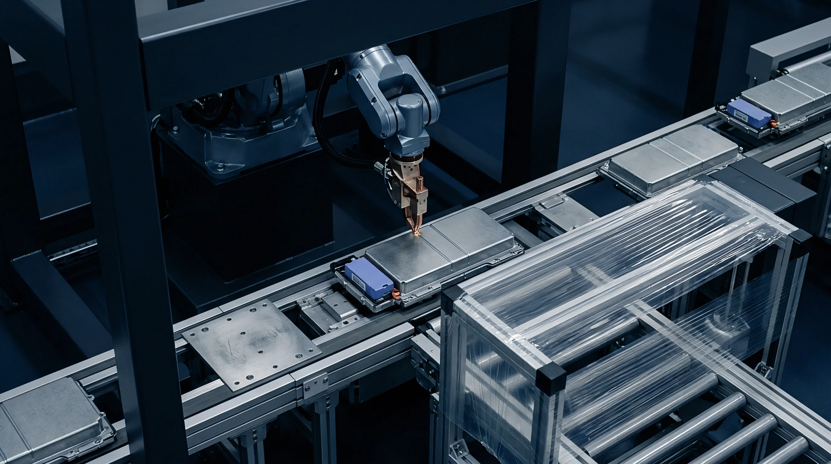
Cavity growth and microscopic contact loss at solid separator boundaries represent the primary physical drivers of capacity fade under dynamic thermal operation. During elevated temperature phases of dynamic cycling, high atomic mobility accelerates lithium vacancy creep toward boundary defects. As thermal ramps reverse toward sub-zero conditions, localized lithium stripping rates outpace interfacial vacancy diffusion rates, nucleating sub-micron cavities along the active electrochemical plane.
These cavities reduce the effective contact area available for ionic transport, forcing localized current density to surge across remaining contact spots.
Interfacial Contact Loss Mechanisms
Electrochemical mass transport across solid interfaces requires atomic-scale physical intimate contact. When non-linear thermal cycling induces mechanical shear, interfacial adhesion forces decay exponentially as micro-delamination propagates. Microscopic surface topography features, such as surface roughness pits from tape casting or vacuum deposition, serve as nucleation sites for interfacial voiding.
Under variable thermal stress, local normal pressure fluctuates rapidly. When contact stress drops below the plastic flow threshold of metallic lithium, vacancies aggregate into planar void networks rather than collapsing under mechanical compression.

Stress Concentrators at Cavity Perimeters
Discontinuities in physical contact reshape internal electric and stress fields inside solid electrolyte separators. Current lines squeeze through surviving contact spots, causing hyper-localized current focusing. This current constriction accelerates localized heating through localized Joule dissipation, creating micro-scale hotspot zones where temperatures exceed bulk pack measurements by dozens of degrees.
Micro-scale thermal expansion within these hotspot zones intensifies localized stress, driving micro-crack initiation into brittle ceramic electrolyte matrices such as lithium lanthanum zirconium oxide.

Electrolyte Creep and Elastic Recovery Limits
Deformation behaviour varies fundamentally between oxide, sulfide, halide, and polymer electrolyte classes under Dynamic mechanical thermal profiles. Sulfide electrolytes display mechanical flexibility that accommodates minor surface roughness, but yield plastically when dynamic stress ramps coincide with peak operating temperatures. Oxide electrolytes resist plastic deformation, maintaining high elastic modulus across high temperature regimes, but exhibit zero stress relaxation, transferring all dynamic thermal strain directly into interfacial shear stresses.
| Electrolyte Chemistry | Young’s Modulus (GPa) | Thermal Expansion (10^-6 / K) | Shear Yield Stress at 25C (MPa) | Void Growth Rate at 5 MPa (nm/cycle) |
|---|---|---|---|---|
| Lithium Lanthanum Zirconium Oxide (LLZO) | 150 – 170 | 15 | 2200 | 0.12 – 0.35 |
| Lithium Phosphorus Sulfur Chloride (LPSCl) | 18 – 25 | 30 | 110 | 1.40 – 2.85 |
| Lithium Indium Chloride (LIC) | 10 – 15 | 28 | 85 | 0.80 – 1.90 |
| PEO-LLZO Composite Polymer | 1.2 – 3.5 | 65 | 12 | 4.50 – 8.20 |
Quantifying failure boundaries across these electrolyte classes requires mapping specific mechanical micro-structural degradation modes observed during dynamic thermal aging:
- Interfacial Cavity Coalescence occurs when sub-micron vacancies aggregate during low-pressure thermal cooling steps, creating macro-scale unbonded planar regions across active area boundaries.
- Localized Current Constriction develops around non-conductive interfacial cavities, raising local current density up to ten times nominal stack rating.
- Micro-Fracture Propagation initiates at cavity perimeters inside rigid ceramic separators due to coupled electric field and thermal expansion stress concentrations.
- Electrolyte Creep Relaxation Fatigue emerges in sulfide and polymer stacks, where continuous pressure fluctuations induce permanent geometric distortion of the solid separator plane.
Non-compliance with UN 38.3 T2 thermal test ramping limits exposes the stack to unrestrained interfacial delamination, invalidating cell-level transportation safety certification.
Failure to constrain dynamic pressure variations within tight target windows leads directly to accelerated impedance growth, localized lithium dendrite penetration along interfacial cracks, and irreversible cell capacity decay.
Hysteresis
Mechanical response loops under dynamic thermal profiles display severe path dependence, creating complex stress-strain loops across cell lifetime. Consider a solid state cell stack featuring a sulfide solid electrolyte paired with a pure metallic lithium anode, clamped in a rigid pack enclosure with metallic Belleville spring fixtures. Assume an initial stack pressure of 5.0 megapascals at 25 degrees Celsius, an active stack thickness of 12.0 millimeters, and an operating temperature envelope fluctuating non-linearly between negative 20 degrees Celsius and 70 degrees Celsius at rate variations up to 10 degrees per minute.

Where Does Solid Electrolyte Creep Limit Interfacial Contact?
Sulfide electrolytes exhibit time-dependent creep at temperatures above 40 degrees Celsius. When the stack reaches 70 degrees Celsius, thermal expansion drives internal pressure up to 11.4 megapascals. At this elevated stress and temperature state, metallic lithium deforms plastically, while the sulfide electrolyte undergoes viscoplastic stress relaxation at a rate of 0.45 megapascals per minute.
Over a 30-minute high-temperature dwell period, stack stress relaxes down to 7.8 megapascals, squishing lithium metal into micro-porous surface features and relaxing external Belleville springs.
When rapid cooling commences at 10 degrees per minute back down to negative 20 degrees Celsius, physical contraction of the stack layers occurs faster than the stress-relaxed electrolyte and anode can mechanically recover. The metallic lithium anode contracts rapidly, but plastic deformation sustained during the high-temperature dwell prevents the material from returning to its original geometry. As a result, internal stack pressure collapses down to 0.8 megapascals at negative 20 degrees Celsius, falling far below the minimum 3.0 megapascal threshold necessary to suppress interfacial vacancy formation during charge transport.
Thermal Ramp Velocity and Stress Accumulation
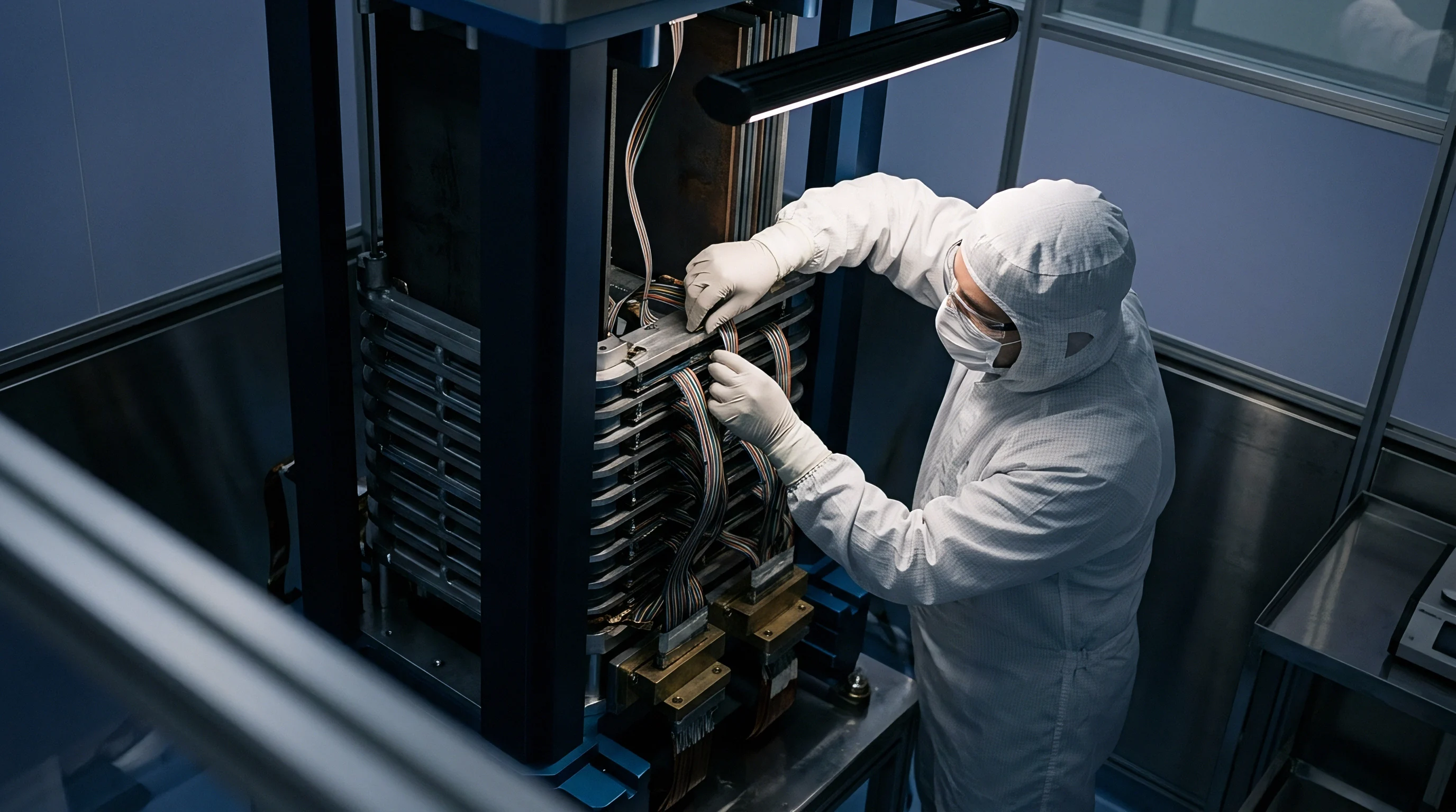
Evaluating the mechanical energy lost per thermal cycle reveals the structural impact of dynamic stress hysteresis. In this worked scenario, peak stack expansion during heating generates a total compressive work input of 4.32 joules per cell stack layer. Mechanical hysteresis losses, absorbed through plastic flow of the anode and viscous creep of the solid separator, account for 1.87 joules per cycle.
This energy dissipation represents permanent micro-structural damage, manifesting as thickness changes, localized edge compression lines, and surface topography roughness redistribution.
Over 500 dynamic thermal loops, cumulative stress relaxation reduces baseline room-temperature stack pressure from 5.0 megapascals to 2.1 megapascals. Mechanical spring hardware calibrated solely for static temperature conditions cannot compensate for this multi-scale compression loss, leaving the interface vulnerable to rapid delamination during subsequent thermal transients.
Spring preloads configured solely for isothermal expansion fail during rapid cooling phases when electrolyte stress relaxation lags behind physical separator contraction.
Cell suppliers frequently attribute thermal degradation to internal chemical side-reactions when physical loss of stack compression pre-load represents the actual root cause of impedance escalation.

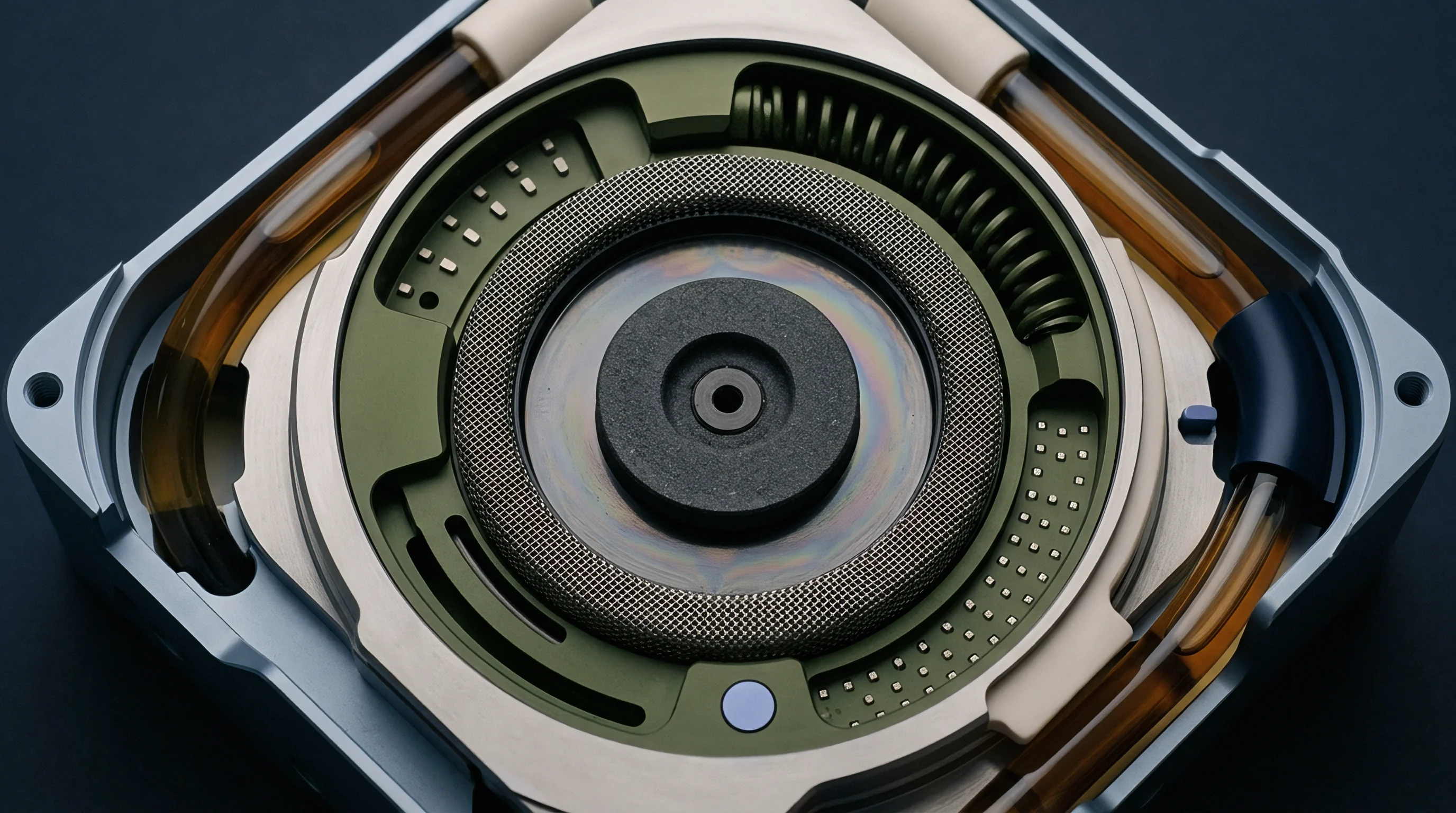
Metrology
Diagnosing non-planar interfacial degradation inside sealed, pressurized solid state stack assemblies demands specialized operational measurement techniques. Standard post-mortem teardown methods destroy internal mechanical stress balances, altering surface contact profiles before physical inspection can take place. Non-destructive operando diagnostic tools must resolve spatial features smaller than two micrometers while operating through heavy steel pressure plates and variable thermal chambers.
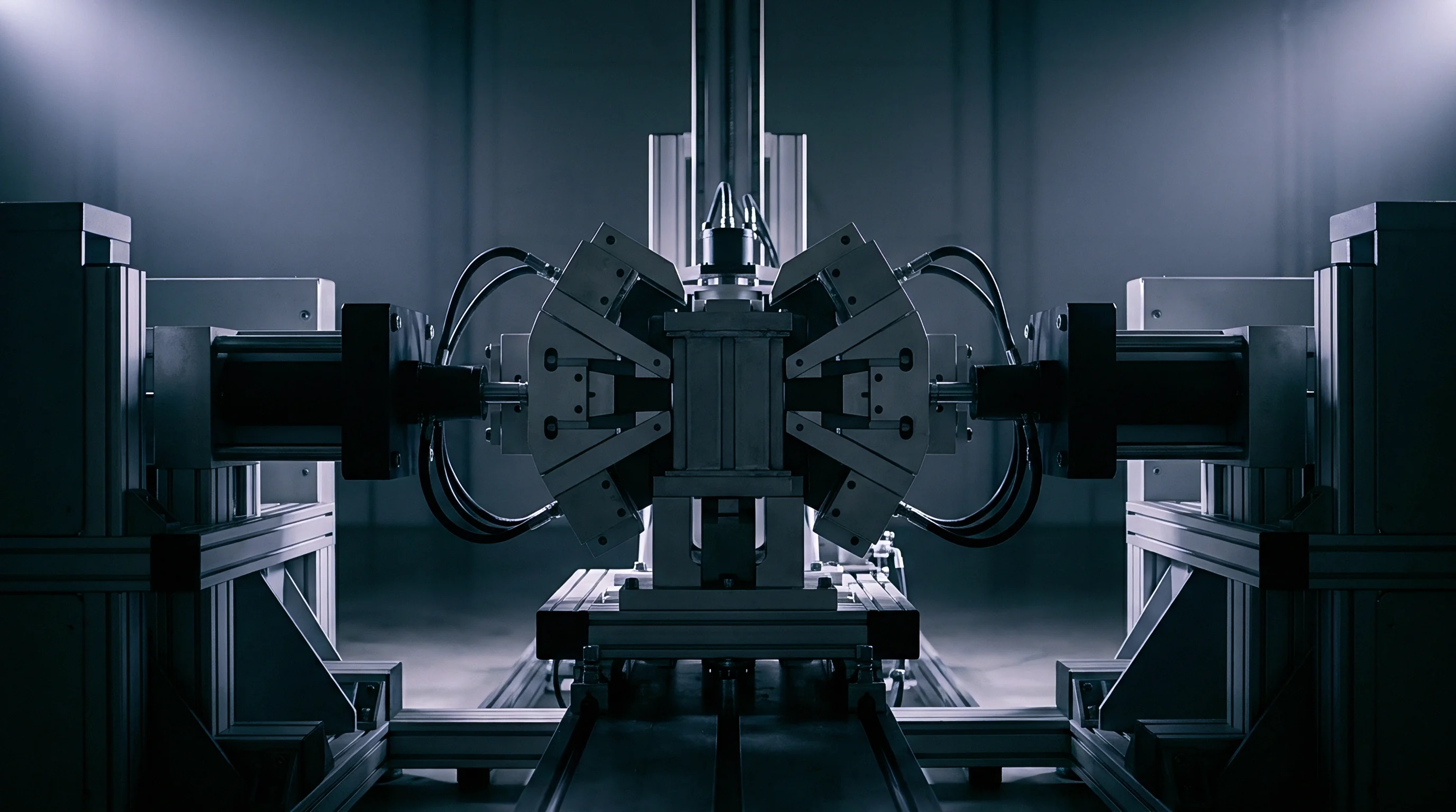
Operando Impedance Deconvolution under Transient Loads
High-frequency electrochemical impedance spectroscopy provides real-time information regarding active contact area changes during dynamic thermal cycling. By measuring complex impedance across frequencies ranging from 1 megahertz down to 10 millihertz during thermal ramps, analytical algorithms separate bulk electrolyte resistance from interfacial charge-transfer resistance. High-frequency intercept values track structural separator bulk properties, while mid-frequency semicircles quantify interfacial capacitance and contact area scales.
Dynamic impedance spectroscopy algorithms must process measurement sweeps within seconds to catch transient phenomena occurring during rapid thermal ramps. Synchronizing spectral acquisition with transient temperature sensors enables precise extraction of temperature-corrected interfacial activation energies. An sudden elevation in apparent activation energy during a cooling transient signals instantaneous micro-delamination and contact spot isolation.
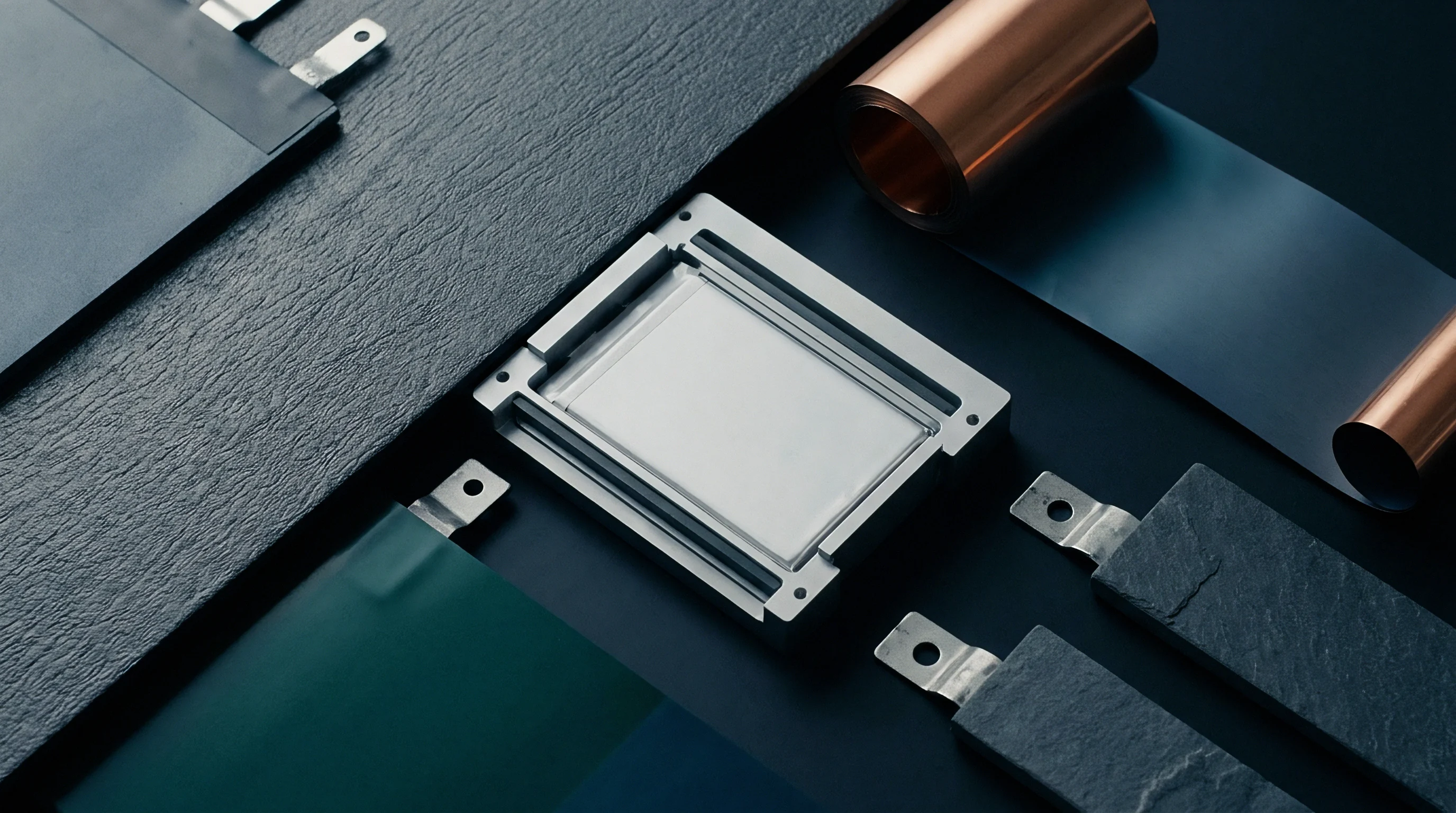
Ultrasonic Pulse Echo Inspection Profiles
Acoustic metrology offers direct spatial mapping of mechanical contact quality inside active cell stacks. Ultrasonic waves transmitted through external pack compression plates reflect strongly off solid-gas interfaces, such as delamination cavities or unbonded zones, while transmitting cleanly across fully bonded solid-solid interfaces. Dynamic acoustic monitoring tracks reflection amplitude coefficients across the planar surface during active thermal cycling.
| Metrology Method | Spatial Resolution | Sampling Frequency | Thermal Chamber Compatibility | Primary Measurable Parameter |
|---|---|---|---|---|
| Dynamic Operando EIS | Area-Averaged | 0.1 Hz – 10 Hz | Full (-40C to 105C) | Interfacial Charge Transfer Resistance |
| Ultrasonic Pulse Echo | 50 um – 200 um | 1 Hz – 50 Hz | Moderate (-20C to 85C) | Acoustic Impedance Mismatch / Contact Ratio |
| Synchrotron X-ray CT | 0.5 um – 2.0 um | 0.001 Hz | Restricted (Custom Cells) | Three-Dimensional Void Volume Distribution |
| Piezoresistive Film Sensing | 1.0 mm – 3.0 mm | 100 Hz | Full (-40C to 125C) | Spatial Contact Stress Mapping |
Pack developers establishing incoming cell lot qualification procedures rely on structured screening workflows to filter vulnerable cells prior to module integration:
- Baseline Acoustic Mapping verifies initial interfacial bonding uniformity across 100 percent of cell active area under target assembly stack pressure.
- Transient Thermal Shock Screening subjects sample cells to 10 rapid thermal cycles between negative 40 degrees Celsius and 85 degrees Celsius while logging continuous dynamic impedance.
- Pressure Decay Verification measures static and dynamic load retention using calibrated load cells integrated into cell test fixtures over 72 hours.
- Post-Cycling Impedance Ratio Analysis computes the change in interfacial charge-transfer resistance relative to baseline bulk resistance after thermal stress exposure.
Continuous real-time impedance tracking provides early indication of contact area loss prior to detectable capacity decay.
Which combinations of acoustic frequency and sensor array density accurately capture localized micro-delamination without introducing thermal measurement artifacts through acoustic coupling gels?


Forecast
Predictive modeling of interfacial degradation across dynamic thermal profiles requires coupling transient fluid-thermal dynamics, structural finite element mechanics, and electrochemical phase-field damage models. Multi-scale simulation tools translate micro-structural material properties into macro-scale pack life projections, replacing costly empirical burn-in testing programs with validated numerical physics engines.

Cohesive Zone Formulations for Solid Separator Interfaces
Cohesive zone modeling represents interfacial separation by inserting zero-thickness element layers between solid electrolyte and electro-active material domains. The constitutive behavior of these cohesive elements follows bilinear or exponential traction-separation laws, parameterized by critical energy release rates and peak shear traction limits. Under cyclic thermal loading, cohesive elements accumulate irreversible fatigue damage based on local dynamic stress amplitudes and temperature-dependent stiffness parameters.
Incorporating temperature dependency directly into traction-separation laws allows simulation models to reflect thermal softening and embrittlement. At high temperatures, critical fracture energy increases due to plastic ductility in metallic components, but initial stiffness drops. At sub-zero temperatures, peak traction strength rises while critical fracture energy falls, making cohesive elements susceptible to catastrophic brittle unbonding under thermal shock impact.
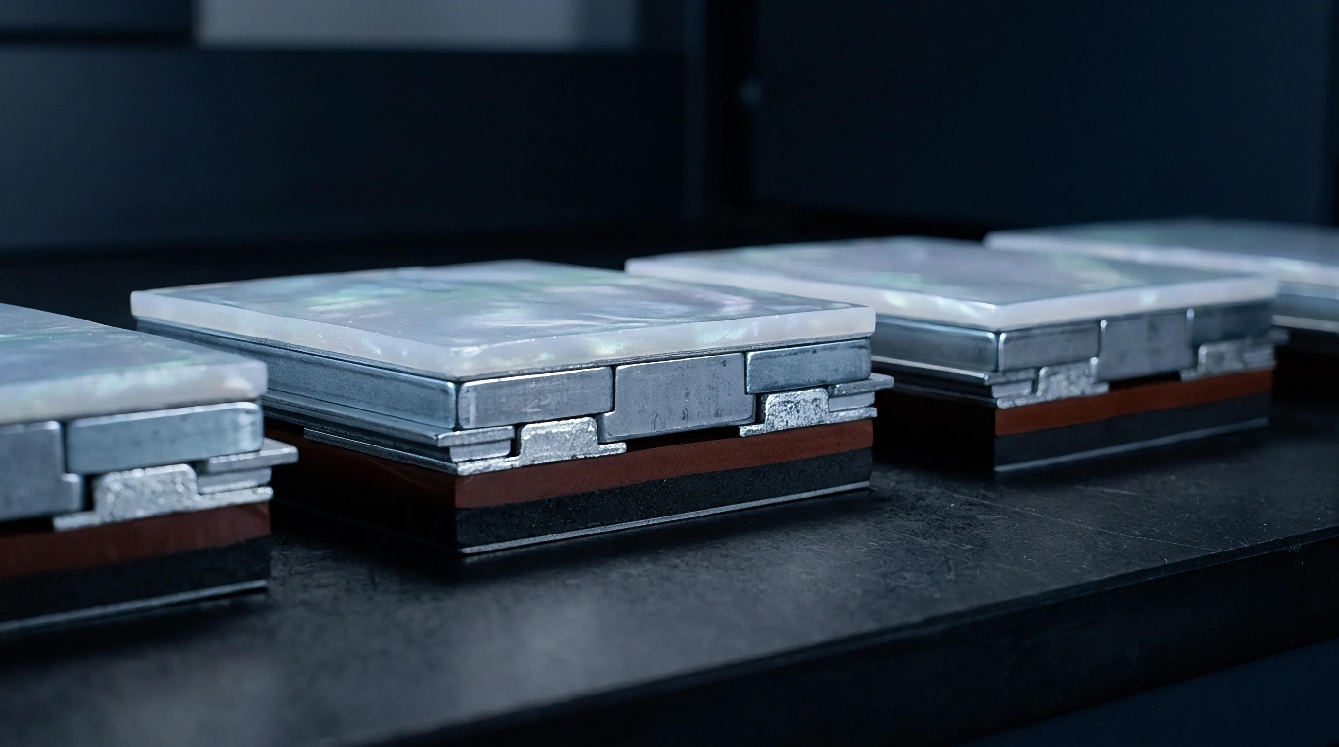
Thermomechanical Finite Element Coupling
Fully coupled thermomechanical finite element simulations solve energy balance and momentum conservation equations simultaneously across complex cell geometries. The model updates localized heat generation terms based on local current densities derived from electro-chemo-mechanics modules, while updating mechanical material properties at every time step based on local temperature distribution fields.
Accurate life prediction mandates a disciplined step-by-step calibration procedure to tune finite element parameters against physical laboratory test data:
- Extract basic temperature-dependent elastic, plastic, and thermal expansion properties for each material layer using dynamic mechanical analysis and dilatometry.
- Measure mechanical fracture toughness and shear strength of the solid electrolyte interface across the full operational thermal range using specialized micro-wedge lap shear tests.
- Subject single-layer solid state pouch cells to controlled linear dynamic thermal profiles inside acoustic and impedance monitoring test chambers.
- Inverse-calibrate cohesive zone traction-separation parameters by matching simulated stress-strain hysteresis loops to measured dynamic load cell outputs.
- Validate the fully coupled multi-physics framework against un-seen non-linear thermal dynamic profiles, comparing simulated capacity degradation rates against observed multi-cell module test outcomes.
Numerical life projections established through validated finite element cohesive zone models enable battery pack architects to optimize mechanical compression module geometry, selecting spring constants and thermal insulation barriers that prevent localized interfacial stress intensity factors from reaching critical fracture limits throughout the target pack warranty life.

Indemnity
Commercial contracts for solid state cell sourcing must explicitly allocate financial and technical risk associated with interfacial degradation under non-linear dynamic thermal operations. Because solid state cell performance depends entirely on external mechanical compression maintained by pack-level hardware, standard cell-only warranty terms create massive legal friction when early cell capacity fade occurs in customer vehicles or grid storage assets.

Warranty Boundary Seams for Variable Compression Hardware
Cell manufacturers typically supply bare solid state pouch or prismatic units, while pack integrators design and manufacture module enclosures, Belleville spring stacks, piezoresistive monitoring sensors, and thermal management cold plates. If interfacial delamination occurs after 18 months of customer operation, cell suppliers routinely claim that pack-level compression hardware failed to maintain target preload pressure across seasonal thermal swings. Conversely, pack integrators argue that excessive internal cell swelling and yield creep exceeded standard mechanical compensation tolerances.
Definitive supply agreements solve this boundary ambiguity by incorporating real-time operational parameter limits into warranty coverage conditions. The technical schedule must define precise allowable ranges for stack pressure, temperature ramp rates, maximum delta temperatures across module plates, and peak thermal shock limits.
| Interface / Property Parameter | Cell Manufacturer Allocation | Pack Integrator Allocation | Verification Metric / Compliance File |
|---|---|---|---|
| Initial Interfacial Adhesion | 100 % Responsibility | 0 % Responsibility | First-Article Acoustic Tomography Certificate |
| Stack Compression Preload Maintenance | Defines Min/Max Range | Engineers Spring Hardware | 72-Hour Thermal Cycle Load Cell Audit |
| Thermal Ramp Shear Stress Limits | Provides FEA Material Model | Validates Module Thermal Path | |
| Interfacial Creep Impedance Rise | Guarantees Max Creep Rate | Maintains Min Pressure Target | Operando Impedance Cycle Log |
Engineering procurement teams establish comprehensive qualification dossiers to protect capital investments when executing volume purchase orders for solid state cells:
- Thermomechanical Material Specification Dossier detailing temperature-dependent moduli, yield stresses, and thermal expansion metrics for all internal cell components.
- Pressure-Temperature Operational Envelope Map defining strict boundary conditions under which cell cycle life warranties remain legally active.
- Independent Laboratory Qualification Certificate verifying cell performance under non-linear dynamic thermal test profiles matching actual field drive cycles.
- Joint Failure Analysis Agreement establishing binding teardown protocols, acoustic inspection criteria, and cost-allocation frameworks for non-conforming field returns.
A standard procurement master service agreement clause dictates that cell warranty obligations remain fully enforceable provided the pack integrator maintains stack compression within specified tolerance bands of plus or minus 0.5 megapascals across all thermal dynamics defined in UN 38.3 T2 testing standards.