Prismatic Cell Thermal Joint Optimization Principles
Optimizing prismatic thermal joints requires matching TIM gap filler rheology to cell face dish tolerances under controlled stack compression.
Heat
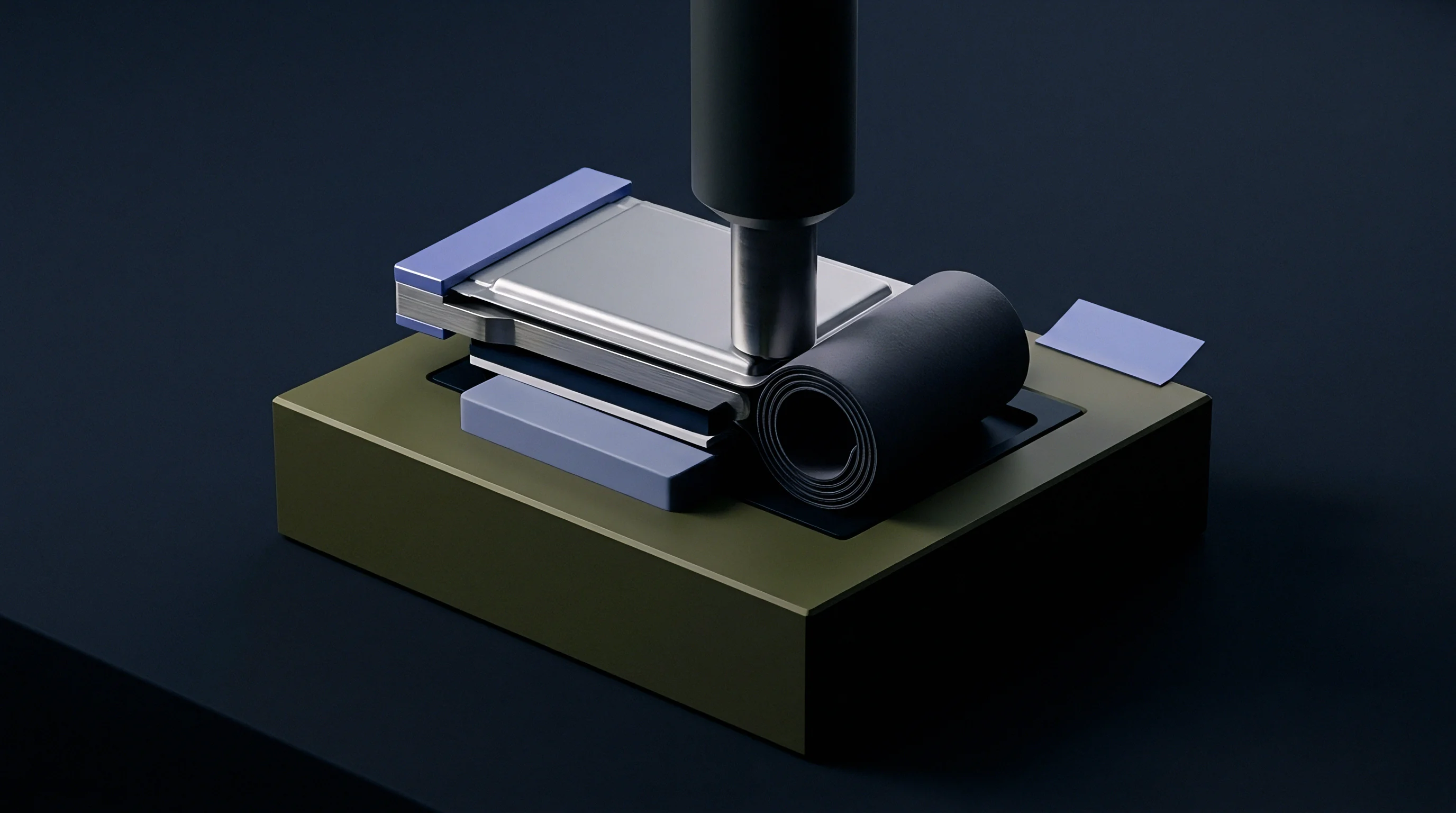
Heat generated within a prismatic lithium-ion cell sheds mostly through the bottom floor and the broad aluminum sides. That heat originates in the stacked or wound electrode rolls, driven by ohmic losses in the current collectors and ion transport resistance through the electrolyte. From the core, thermal energy moves across the packaging, traversing dielectric insulation films and internal gas gaps before reaching the outer aluminum casing.
Transferring that thermal load into a liquid cold plate requires an interface engineered to limit temperature drops across each successive boundary.
Total thermal resistance across the joint is a function of bulk material conductivity and contact resistance at the surfaces. When a bare aluminum cell sits straight against a cold plate, contact resistance dominates the thermal circuit. Surface asperities from drawing or extrusion limit direct contact to scattered microscopic peaks, leaving the interstitial valleys filled with trapped air.
Dry air conducts only around 0.026 W/m·K, so these microscopic pockets effectively choke off heat transfer and constrict thermal flux to the contact asperities. Clamping harder crushes those peaks somewhat, but mechanical pressure cannot close the micro-voids without buckling the thin aluminum can.
Applying a thermal interface material cuts contact resistance by replacing trapped air with a resin that wets to the aluminum topography under moderate clamp loads.
Face flatness variations across large prismatic cells make interfacial heat transfer far less predictable. Casing tolerances can introduce bow or dish departures greater than 0.5 mm over a 200 mm span. Clamping a flat cooling plate against a dished cell face leaves wide clearance gaps around the perimeter or in the middle.
Heat flux shifts accordingly: tight contact patches run cooler under high heat flux, while wide-gap zones insulate the cell and develop hotspots. Sizing the interface layer therefore depends on matching nominal material thickness to the peak-to-valley spread of the mated surfaces.
Pack architectures typically run cooling along the bottom floor, up the broad side faces, or across both surfaces simultaneously. Chilling the bottom keeps the module footprint compact, though the base offers relatively little surface area for the cell volume above it. Chilling the sides takes advantage of the wide lateral faces ~ lowering heat flux density and pulling down core temperatures ~ at the direct cost of volumetric packaging efficiency.
Deciding between them comes down to trading volumetric energy density against the peak cell temperature delta permitted during fast charging.
| Interface Architecture | Interface Material Type | Nominal Joint Conductivity (W/m·K) | Typical Joint Impedance (K·cm²/W) | Target Joint Pressure Window (MPa) |
|---|---|---|---|---|
| Direct Mechanical Dry Contact | None (Air Gap present) | 0.03 to 0.05 | 8.5 to 12.0 | 0.30 to 0.60 |
| Bottom Cold Plate Pad | Silicone Elastomer Gap Pad | 1.50 to 3.00 | 2.1 to 3.5 | 0.20 to 0.40 |
| Structural Wet Dispense | Two-Part Polyurethane Adhesive | 1.80 to 2.50 | 1.2 to 2.0 | 0.05 to 0.15 |
| High-Density Side Plate | Thermally Conductive Epoxy | 3.00 to 4.50 | 0.6 to 1.1 | 0.10 to 0.25 |
Any void left unfilled inside the thermal joint acts as an insulator rather than a conductor.

Clamp
Prismatic modules require mechanical clamping to hold their geometry and restrain motion inside the electrode stack. Graphite and silicon-doped anodes expand and contract cyclically as lithium ions shuttle in and out, and over hundreds of cycles, that breathing turns into permanent thickness growth. Left unconstrained, cells risk internal delamination, localized lithium plating, and accelerated capacity loss.
Applying steady external pressure curbs this mechanical decay and keeps the thermal interface seated firmly against the cooling surfaces.
Stack-up tolerances quickly accumulate across multi-cell assemblies. An individual prismatic can often carries a thickness tolerance of roughly plus or minus 0.3 mm, meaning a twenty-cell module can vary by plus or minus 6.0 mm from nominal unless cells are graded and sorted beforehand. When rigid endplates and fixed tie-rods clamp that stack, dimensional variation translates directly into uneven contact pressure.
Oversized cells absorb punishing local loads, while undersized ones sit loose enough to compromise thermal contact with the cold plate.
Inter-cell foam pads absorb these tolerance stacks while maintaining an elastic preload on each face. Microcellular polyurethane and silicone foams retain consistent load-deflection behavior from -40°C to +85°C, acting as distributed springs that keep face pressure inside the design window. This compliance prevents excessive stress at full state of charge and retains contact pressure during cold soaks.
Specifying these pads requires accounting for long-term stress relaxation over years of field exposure.
Over-clamping causes its own set of problems, damaging separators and warping the cooling interfaces. When compressive loads exceed design limits, aluminum casings bulge into available clearances, pinching cell edges and lifting the center of the base off the cooling plate. That distortion tears uneven bondlines open, shearing rigid structural adhesives or squeezing soft thermal gels entirely out of the gap.
Flawed clamping architecture undermines joint reliability through several predictable failure modes over the pack lifecycle:
- Interfacial Gap Formation leaves air gaps over the cooling plate whenever local clamping pressure slips below wet-out requirements.
- Adhesive Shear Fracture develops when differential thermal expansion between the aluminum can and the cold plate strains the bond past its limit.
- Thermal Material Pump-Out squeezes uncrosslinked silicone compounds out of the interface under cyclical swelling.
- Structural Wall Deformation dishes the thin casing floor away from the cold plate when tie-rods over-tighten the stack.
Uncontrolled compression loads can trigger joint fractures, uneven cell aging, and early pack capacity collapse.


Bond
Dispensing a liquid thermal interface material onto the cold plate establishes an unbroken conductive bridge to the cell bottoms. Robot heads deposit two-part polyurethane or silicone resins in parallel beads, serpentine tracks, or cross-hatched patterns. When the cell module presses down into the wet adhesive, insertion forces squeeze the beads flat into a continuous layer.
Fluid rheology, yield stress, and shear thinning determine how cleanly that resin fills tight clearances without spilling over perimeter dams.
What Gap Tolerance Breaks EOL Thermal Transfer?
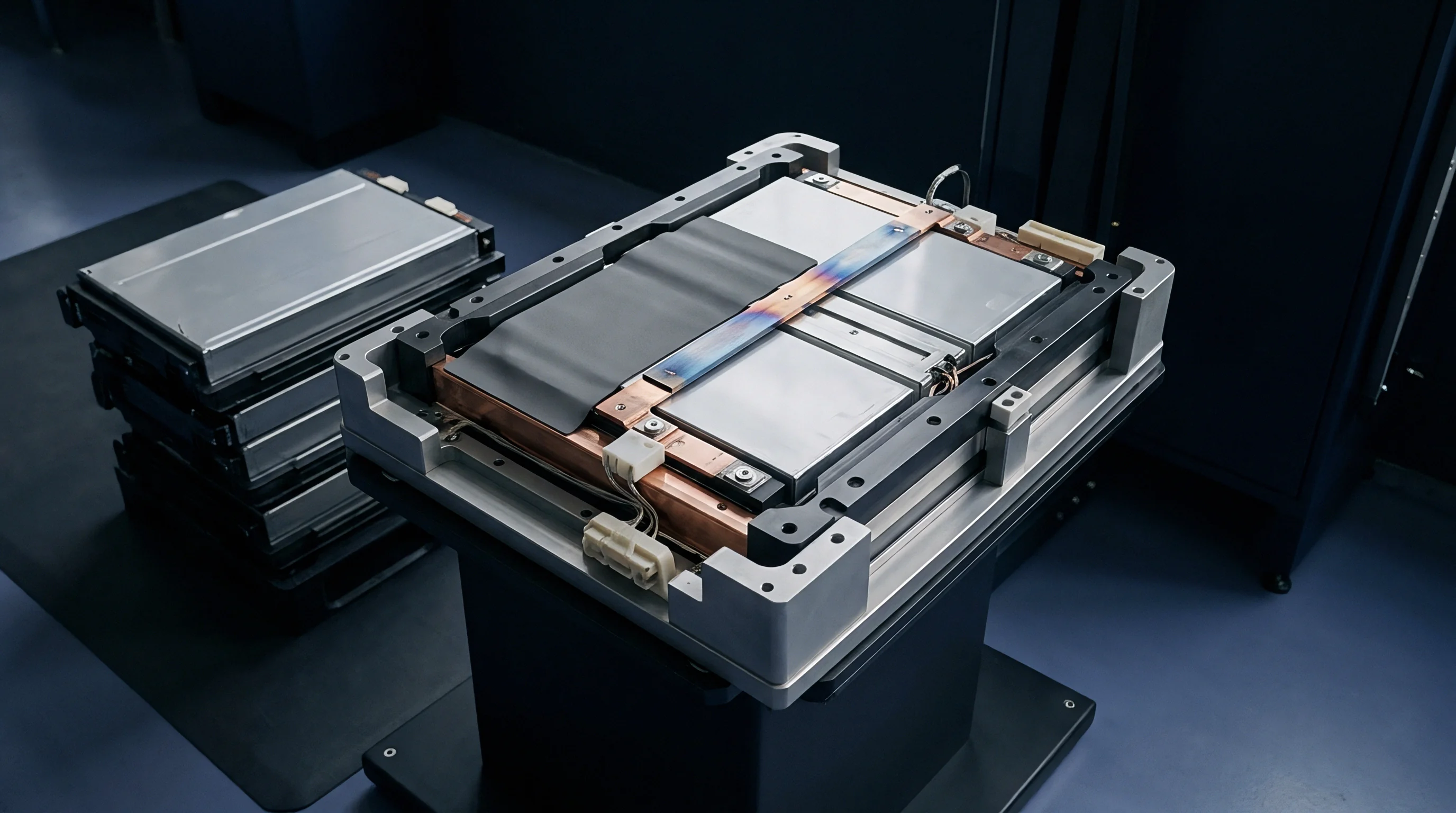
Bondline thickness sets bulk thermal resistance across liquid joints. While shaving gap thickness shortens the conduction path, casing dish and cold plate tolerances dictate the real minimum thickness achievable in production. Targeting a nominal 0.5 mm bondline often means managing local variations between 0.2 mm and 1.2 mm across one module footprint.
If clearance pinches below the size of the ceramic filler particles, alumina or aluminum nitride grains bridge the gap, preventing the cells from seating and creating concentrated stress points on the casing floor.
Air entrapment during dispensing remains a major yield hazard on high-speed lines. When parallel adhesive beads coalesce under an advancing cell, air easily gets pinched between meeting fluid fronts, curing into permanent voids that cripple local heat transfer. Tuning bead geometry, dispense nozzle velocity, and cell insertion rate lets the adhesive front sweep air ahead of itself and out the perimeter, ensuring complete contact across critical cooling zones.
| Process Variable | Operational Target Value | Lower Toleranced Limit | Upper Toleranced Limit | Impact on Joint Integrity |
|---|---|---|---|---|
| Mix Ratio Accuracy | 1:1 Volumetric | 0.95:1 Volumetric | 1.05:1 Volumetric | Off-ratio mix causes incomplete cure and lowered lap shear strength |
| Dispense Rate | 25.0 g/s | 22.5 g/s | 27.5 g/s | Low mass leads to dry voiding; high mass causes spillover into busbars |
| Insertion Velocity | 5.0 mm/s | 2.0 mm/s | 8.0 mm/s | Excessive speed traps air pockets under broad prismatic cell bottoms |
| Pot Life Window | 15.0 min at 23°C | 10.0 min at 23°C | 20.0 min at 23°C | Exceeding window increases viscosity and prevents proper squeeze-out |
Liquid gap filler application relies on a tightly sequenced series of automated steps during pack assembly:
- Surface Plasma Treatment cleans and activates the aluminum cold plate, lifting surface energy above 54 mN/m so the adhesive wets out thoroughly.
- Automated Bead Dispensing meters two-part resin through dynamic mixing nozzles directly onto defined target zones of the plate.
- Laser Profilometry Verification inspects bead height and continuity before module drop-in to catch skips or underweight dispense runs.
- Controlled Cell Insertion presses the cell module down at programmed speeds to spread the resin outward without trapping air pockets.
- Fixed Gap Curing locks the module at its target bondline height until the adhesive passes its gel point under temperature control.
Interfacial shear strength must withstand cell swelling forces to keep the thermal bond from tearing loose during high-rate charging.
While gap filler rheology is stated to achieve complete wet-out under zero insertion force, line measurements consistently show uncompressed beads leaving over thirty percent of the target contact area dry.
Swell
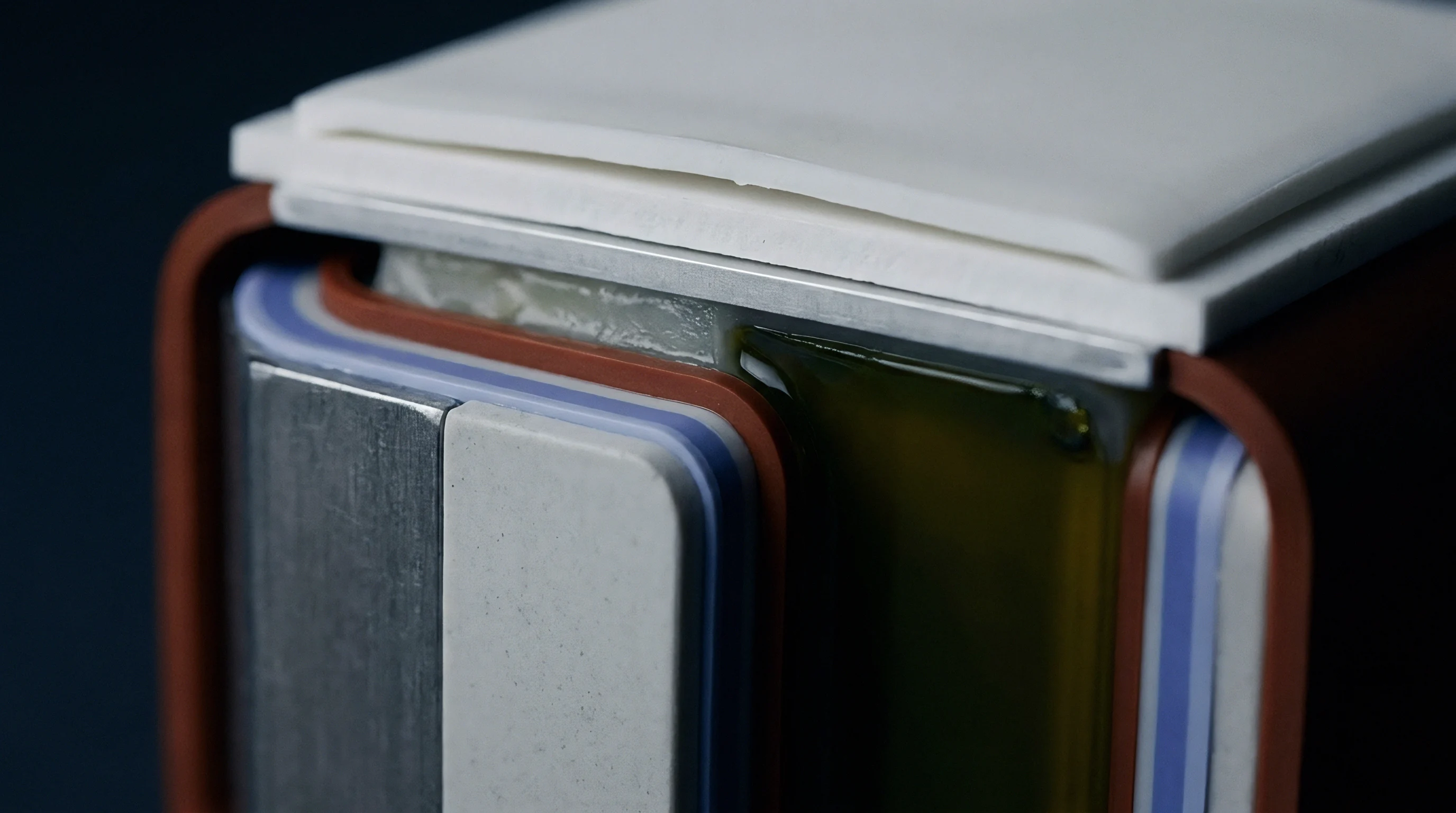
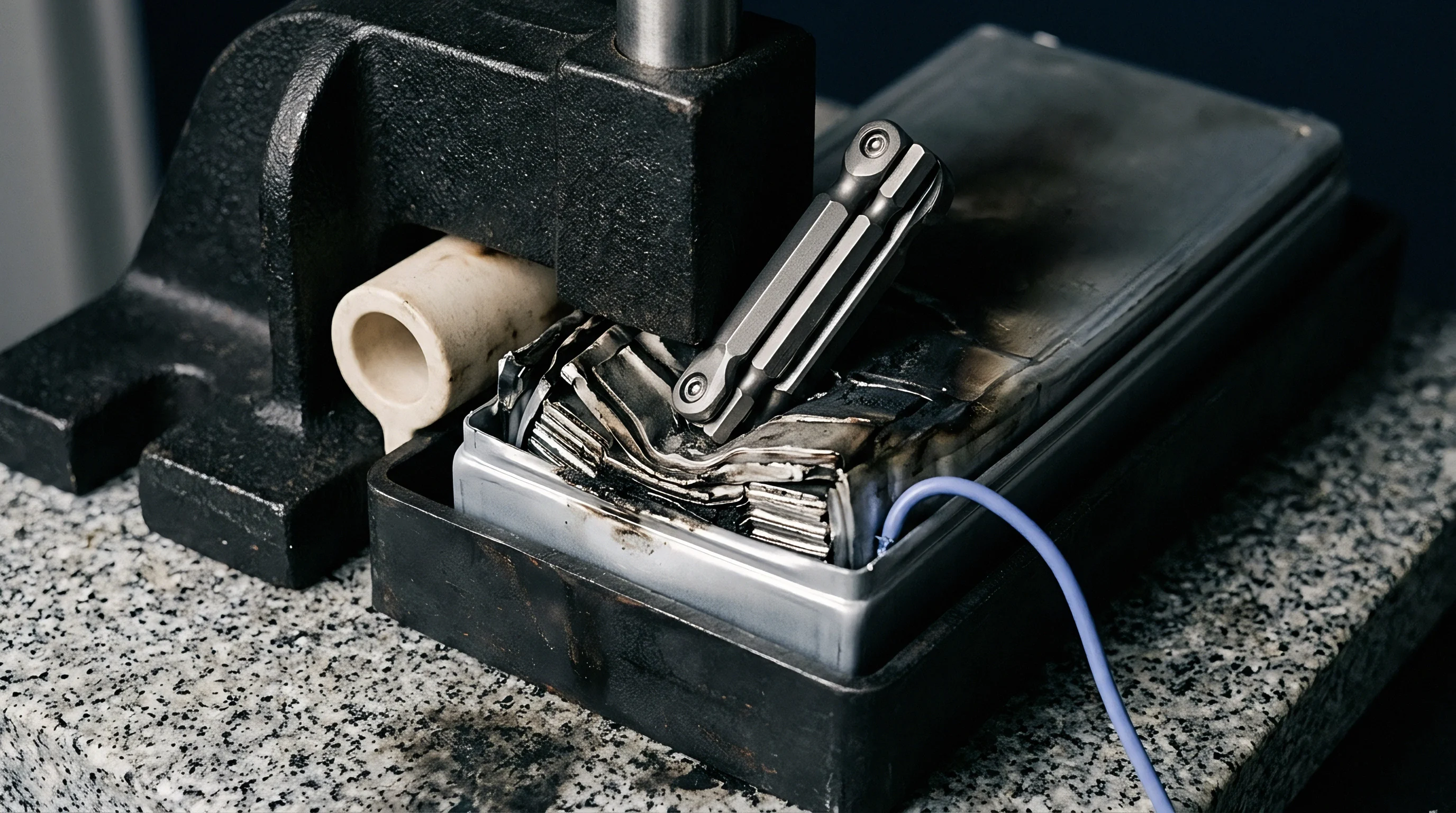
Cell swelling under load puts multi-axial mechanical stress on the thermal interface. Reversible breathing during cycling introduces continuous dynamic displacement, while gradual solid-electrolyte interphase buildup drives a permanent increase in static pressure over time. Together, these forces generate persistent shear across structural adhesive layers and elastomeric pads.
Interface life ultimately hinges on the material’s fatigue endurance and its capacity for elastic recovery under constant micro-motion.
In cell-to-pack architectures, lap shear fatigue resistance determines whether the interface holds together. Structural polyurethane joints anchor cell bottoms directly to the tray, acting as both mechanical fasteners and thermal paths. Hard acceleration and fast charging heat the cell walls faster than the chilled plate beneath them, and this differential expansion subjects the thin bondline to cyclical shear strain.
After thousands of cycles, shear fatigue sparks micro-cracks along the interface, which elevates thermal resistance and weakens pack stiffness.
Non-structural gap fillers suffer from viscoelastic creep, drifting away from high-stress regions over time. These silicone and polyurethane formulations are heavily loaded with ceramic powders, and under steady pressure from swollen cells, the polymer matrix flows outward toward open perimeter margins. That migration strips conductive mass from underneath the cell centers, creating sharp temperature gradients across the base and compromising cooling balance.
Extended exposure to heat and humidity degrades the polymer backbone of cured gap fillers. In polyurethanes with vulnerable ester linkages, hydrolysis destroys cohesive strength, breaking firm elastomeric bonds down into tacky grease. As chemistry breaks down, bulk thermal conductivity drops and road vibration finishes off the weakened joint.
Pack engineers must define precisely how much interface degradation a joint can sustain before the assembly fails operating specifications.
Proof
Validating a thermal joint calls for a mix of inline production controls and destructive lab qualification. On the assembly line, inspection catches immediate defects in bead mass, interface wet-out, and wet bondline thickness. In the test lab, finished modules face accelerated environmental stresses to track how thermal impedance drifts under years of simulated mechanical, thermal, and chemical aging.
Steady-state testing yields repeatable numbers for bulk conductivity and interfacial contact resistance. Built to ASTM D5470 guidelines, test stands pass a controlled heat flux through coupon assemblies clamped between calibrated reference bars, deriving total impedance directly from temperature drops across the interface. Transient plane source methods complement this by measuring dynamic heat dissipation around a flat sensor disk inserted into the material, isolating local bulk conductivity.
End-of-line thermography spots voids and delaminated zones inside closed battery modules without teardowns. Test rigs pulse high current through the cells for several seconds while thermal cameras track transient heat signatures on the cooling plate. Voids choke off heat conduction, creating cold patches on the plate exterior alongside corresponding hot spots on the cell tops.
Vision algorithms compare these thermal maps against baseline profiles to flag defective packs on the spot.
| Verification Stage | Test Standard / Method | Applied Operating Condition | Acceptance Pass Criteria | Failure Detection Mode |
|---|---|---|---|---|
| Inline Dispense Check | 3D Laser Profilometry | 100% Surface Coverage Scan | Bead height within ±0.15 mm | Low dispense mass or bead gap |
| Inline Contact Check | Active Pulsed Thermography | 200 A current pulse for 10 s | Thermal resistance delta under 10% | Interfacial voids or air gaps |
| Qualification Aging | ISO 16750-4 Thermal Shock | -40°C to +85°C, 500 cycles | Zero joint delamination | Adhesive bond fatigue cracking |
| Vibration & Shock | UN 38.3 Mechanical Test | Random Vibration 10 Hz–200 Hz | Thermal impedance stable within 5% | Cohesive interface tearing |
Structuring a qualification plan requires balancing line takt times against engineering risk:
- Thermal Impedance Budget sets the upper limit on temperature drop across the joint during fast charging.
- Inline Cycle Takt Time determines whether active thermography fits within station cycle limits or if inline checks must rely on profilometry alone.
- Maximum Deflection Allowance caps the mechanical displacement the joint must tolerate under end-of-life cell swelling without peeling.
- Environmental Test Exposure defines thermal shock, humidity, and chemical immersion schedules for batch qualification.
Active thermography flags unbonded interface zones within ten seconds of applying a current pulse.
Standard supply contracts typically stipulate that joint thermal resistance cannot climb more than fifteen percent above baseline following UN 38.3 mechanical shock and vibration exposures.
Ledger
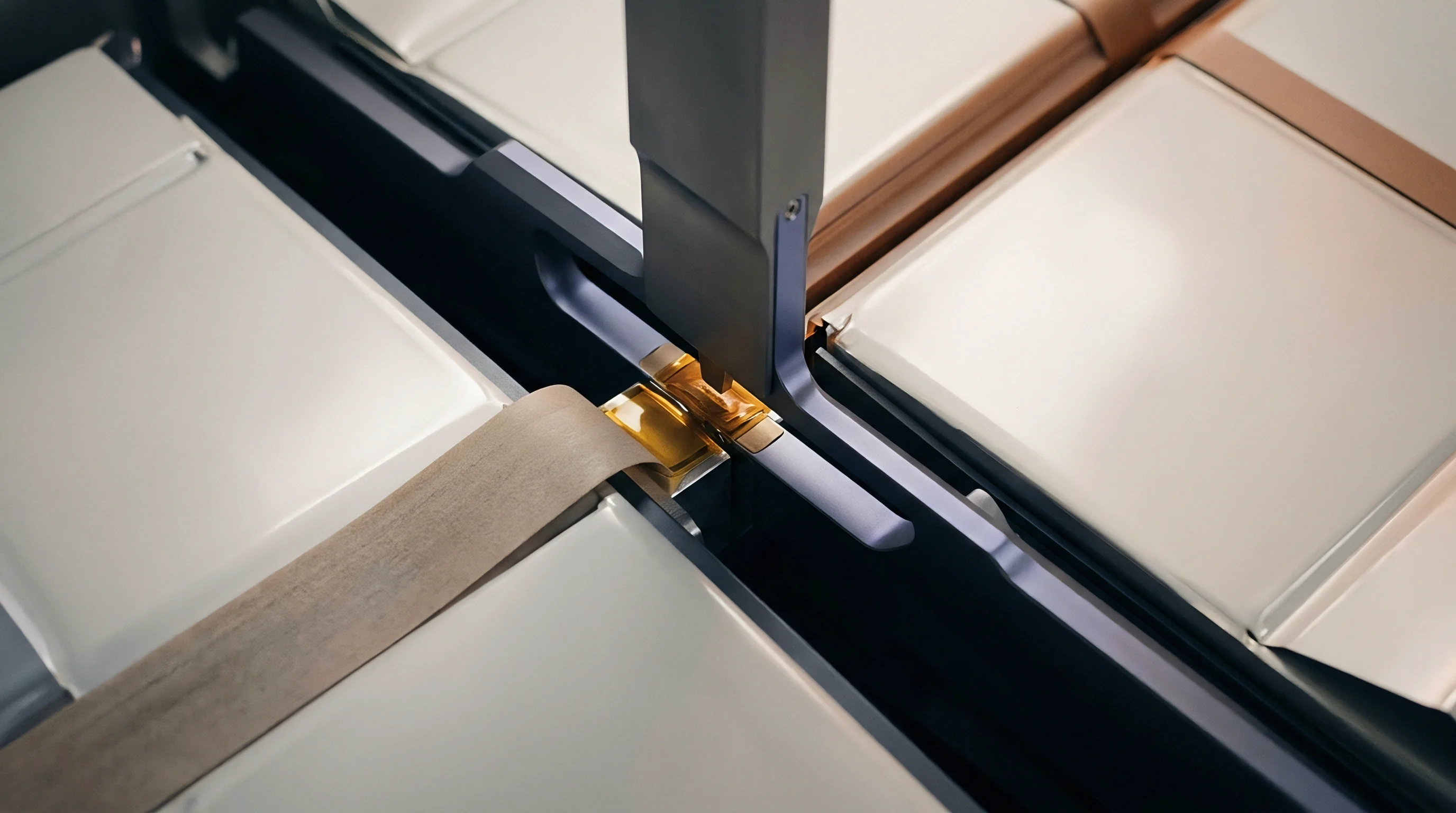
Contractual boundaries around thermal joints demand clear divisions of responsibility between cell manufacturers, material formulators, and module integrators. Cell data sheets define factory-gate limits for can dimensions, surface roughness, and face dishing. From there, the pack integrator carries warranty liability if the chosen thermal interface cannot accommodate those documented casing tolerances or if dispense automation lays down bad bead profiles.
Tooling capital for interface assembly goes mainly toward robotic motion, meter-mix heads, and vision inspection systems. Equipping a line with automated liquid dispensing runs between 150,000 USD and 450,000 USD, depending on degasification hardware, volumetric accuracy, and line speed requirements. Amortizing that machinery over projected pack volumes sets the per-unit assembly overhead, steering the architecture toward either automated wet dispensing or pre-cut elastomeric gap pads.
Formulated adhesives and gap fillers represent a major line item on the pack bill of materials. Standard two-part polyurethanes rated at 2.0 W/m·K cost between 15 USD and 30 USD per kilogram, but pushing performance past 4.0 W/m·K drives prices beyond 80 USD per kilogram because of the spherical alumina or boron nitride filler loadings required. Justifying high-conductivity chemistries requires evaluating whether thermal gains translate into meaningful improvements in fast-charge capability per dollar.
Procurement packages enforce quality through several foundational compliance records:
- Rheological Qualification Dossier logs resin viscosity, yield stress, working life, and shelf stability across the plant operating temperature window.
- Thermal Impedance Certificate establishes measured interface conductivity under target mounting pressures.
- Dispense Equipment Calibration Log tracks mix ratio monitoring, dispense weight consistency, and robot path repeatability.
- Joint Reliability Test File documents thermal shock, vibration, and aging results verifying long-term interface survival.
Assigning clear joint ownership keeps cell warranties intact and gives manufacturing hard quality gates at the dispense station. Pinning down casing tolerances, resin storage rules, and inline inspection criteria contains thermal risk well before ramp-up.