Quantifying Wetted Friction Coefficients to Prevent Internal Stack Slippage
Wetted friction coefficients drop up to sixty percent in flooded cell stacks, demanding calculated external module pre-charge pressure to prevent internal layer slip.
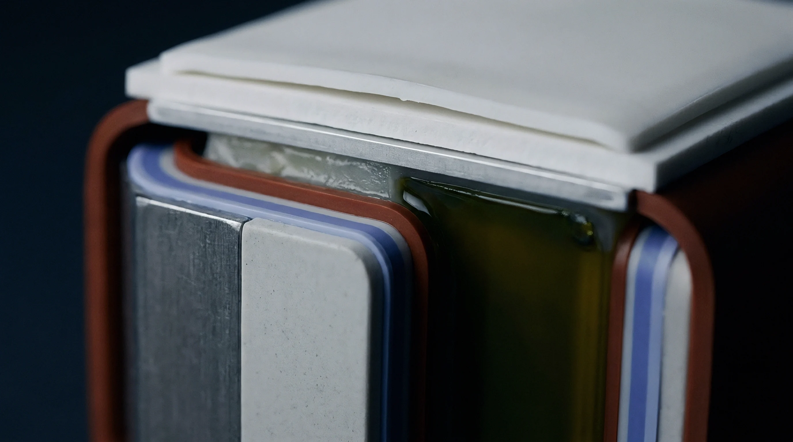

Shear
Lithium intercalation causes internal volume changes that build lateral stress inside prismatic and pouch cell stacks. As graphite and silicon-doped anode layers expand and contract over charge cycles, individual plies take on periodic loads parallel to the electrode plane. If these loads overcome static friction between adjacent layers, micro-displacement follows.
This shift between separator films, current collectors, and active coatings distorts the geometry engineered into the cell core.
Inside the compressed stack, liquid electrolyte acts as a boundary lubricant. Organic carbonate solvents like ethylene carbonate, dimethyl carbonate, and ethyl methyl carbonate drop the un-wetted friction coefficient between polyolefin separators and graphite anodes by up to sixty percent. Dissolved lithium hexafluorophosphate salt further alters boundary layer viscosity and surface tension.
As a result, a stack built with adequate dry compression can lose its mechanical lock once flooded with electrolyte during formation.
Separator displacement under dynamic stack breathing initiates micro-shorts when edge margins drop below 0.5 mm.
Hundreds of deep-discharge cycles accumulate these micro-displacements into macro-level stack distortion. Overhang margins meant to stop dendrite growth along anode edges fall out of alignment, reducing local area ratios and driving lithium plating around the perimeter. Repeated sliding also breaks down the ceramic coating on wet-process polyethylene separators, shedding free alumina particulates inside the active cell volume.
Internal stack movement creates distinct operational failures in high-density pouch and rigid prismatic cell designs:
- Active material shedding happens when high friction drag pulls composite coatings off copper or aluminum collector foils during high-expansion cycles.
- Separator pinhole formation results from localized abrasion between hard alumina particles and thin polymer membranes under high compression.
- Tab fatigue cracking stems from continuous lateral shifting of the jellyroll or pouch stack relative to fixed ultrasonic weld terminals.
- Edge alignment loss exposes cathode active areas directly to non-overhang anode sections, accelerating capacity fade and creating localized hot spots.
Ignoring wetted friction drops during cell stack design leads to uncontained internal shear, causing premature impedance growth and short-circuit field failures.
Contact
Friction coefficients inside a cell depend heavily on the texture and chemistry of the contacting layers. Separator suppliers apply various surface treatments to tune electrolyte wetting, thermal shutdown speed, and mechanical toughness. Dry alumina ceramic coatings feature high surface roughness, giving elevated dry friction coefficients against graphite anodes.
Once electrolyte wets the interface, however, solvated polymer chains and carbonate liquid films change interfacial shear behavior entirely.
Testing wetted layer friction requires isolating normal force, sliding speed, surface roughness, and electrolyte saturation. In cells using gel-polymer binders or plasticizing additives, the shift from static friction to kinetic sliding happens at lower force thresholds. Polyvinylidene fluoride coatings swell in carbonate solvents, forming a soft boundary layer that alters contact mechanics under compression.
The table below outlines typical static and kinetic friction coefficients for standard cell interfaces measured under a normal stress of 0.5 MPa at 25 degrees Celsius.
| Interface Pair | Electrolyte State | Static Friction Coefficient (mu_s) | Kinetic Friction Coefficient (mu_k) | Surface Roughness Ra (um) |
|---|---|---|---|---|
| Uncoated PE Separator / Graphite Anode | Dry | 0.38 ± 0.03 | 0.31 ± 0.02 | 0.12 |
| Uncoated PE Separator / Graphite Anode | Wetted (1.0M LiPF6 EC:EMC) | 0.18 ± 0.02 | 0.14 ± 0.01 | 0.12 |
| Al2O3 Ceramic Coated Separator / Graphite Anode | Dry | 0.55 ± 0.04 | 0.46 ± 0.03 | 0.45 |
| Al2O3 Ceramic Coated Separator / Graphite Anode | Wetted (1.0M LiPF6 EC:EMC) | 0.29 ± 0.02 | 0.23 ± 0.02 | 0.45 |
| PVDF-HFP Coated Separator / NMC811 Cathode | Dry | 0.42 ± 0.03 | 0.36 ± 0.03 | 0.28 |
| PVDF-HFP Coated Separator / NMC811 Cathode | Wetted (1.0M LiPF6 EC:EMC) | 0.22 ± 0.03 | 0.17 ± 0.02 | 0.28 |
| Boehmite Coated Separator / Silicon-Graphite Anode | Wetted (1.0M LiPF6 EC:EMC) | 0.26 ± 0.02 | 0.21 ± 0.02 | 0.38 |
Anode composition also sets the threshold for layer sliding. Adding silicon increases volumetric breathing from under ten percent in pure graphite to over twenty percent in mixed silicon-graphite matrices. This added volumetric strain generates larger lateral forces.
If the wetted kinetic friction coefficient falls below 0.20, standard assembly pressures cannot hold stack layers in place during fast-charge expansion pulses.
Higher surface roughness on ceramic separator coatings maintains micro-contact points through liquid films, preventing total hydrodynamic levitation at the boundary.

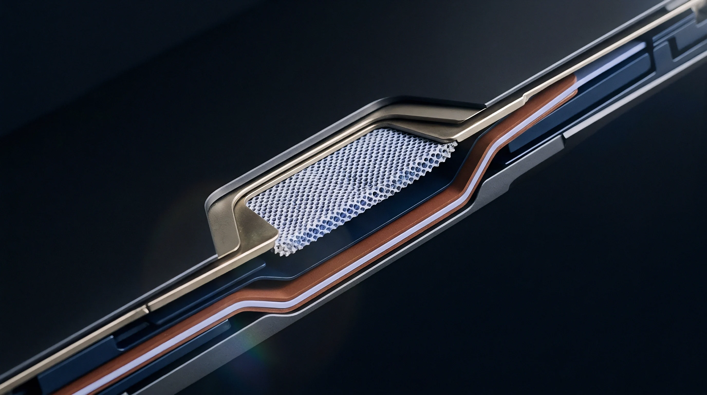
Rheology
Fluid behavior between compressed electrode sheets follows boundary and mixed lubrication regimes. Operating temperature, pressure gradients, and sliding velocity set the film thickness between polymer separator and porous electrode matrix. Low temperatures increase electrolyte viscosity, elevating viscous drag while resisting direct surface contact.
High temperatures thin the boundary film as solvent viscosity drops, shifting contact toward micro-asperity sliding.

When Does Separator Slip Initiate under Dynamic Stack Breathing?
Slip occurs when local expansion rates generate tangential shear stresses exceeding the product of instantaneous normal pressure and wetted static friction. Fast charging drives rapid, uneven lithium insertion at the outer edges of electrode sheets. Temperature gradients across the cell core worsen this effect ~ warmer center regions expand faster than cooler perimeters, squeezing liquid electrolyte out of the central porous network and spiking fluid film pressure at perimeter boundaries.
Uncontained stack shear slip invalidates UN 38.3 vibration compliance by compromising internal electrical isolation.
Electrolyte additives used to stabilize the solid-electrolyte interphase also change surface tension and film lubrication. Vinylene carbonate and fluoroethylene carbonate increase boundary layer viscosity at electrode surfaces. Over repeated thermal cycles, solvent breakdown products and dissolved transition metals alter the rheological properties of free liquid in the pouch, shifting friction dynamics over the operating life of the pack.
Factory formation compression reduces initial layer misalignment, though post-formation vacuum sealing alone does not ensure permanent friction locking without external module pressure.
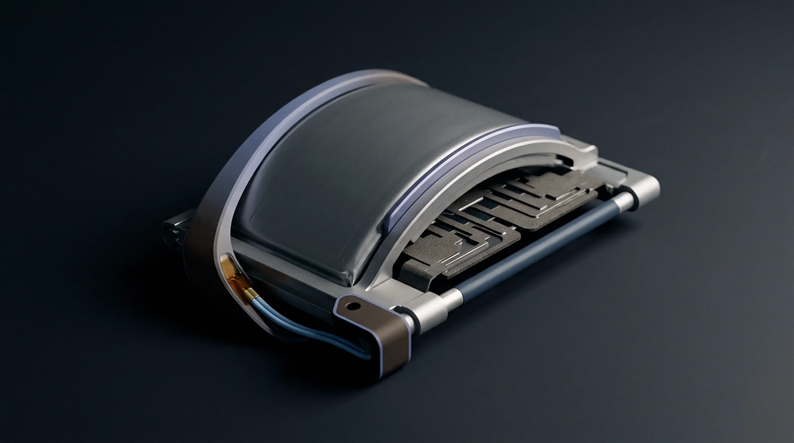
Gauge
Measuring wetted friction coefficients accurately requires test equipment built for inert dry-glovebox environments. Standard ASTM D1894 film friction test methods fail to replicate internal stack conditions. Rigs tailored for cell components operate at normal pressures matching active battery conditions ~ from 0.1 MPa to 3.0 MPa ~ while recording micro-Newton displacement forces.
The bench measurement process follows a strict mechanical and environmental protocol:
- Punch rectangular samples of separator film and coated electrode sheets using clean precision dies to prevent edge burrs.
- Mount the electrode substrate flat onto a temperature-controlled stainless steel baseplate with vacuum hold-down channels.
- Attach the separator sample to a low-mass sliding sled linked to a load cell rated for sub-gram sensitivity.
- Dispense a measured volume of electrolyte ~ typically 50 microliters per square centimeter ~ across the electrode surface using an automated micropipette inside an argon-filled enclosure.
- Apply the target normal stress using calibrated deadweights or an inline mechanical actuator.
- Drive the baseplate laterally at a controlled speed matching cell expansion rates, typically between 0.01 millimeters per second and 1.0 millimeter per second.
- Log load cell resistance data at 100 Hertz or higher to capture peak static breakout force and steady-state kinetic sliding force.
Static friction coefficients are calculated from the ratio of peak horizontal breakout force to applied normal load, while kinetic friction values use the average horizontal force recorded over a 10-millimeter displacement stroke. Environmental control is critical: relative humidity above two parts per million hydrolyzes lithium salts into hydrofluoric acid, altering separator ceramic coatings and distorting test data.
How does long-term electrolyte aging change the mechanical shear threshold between polyolefin films and high-nickel cathode surfaces?
Constraint
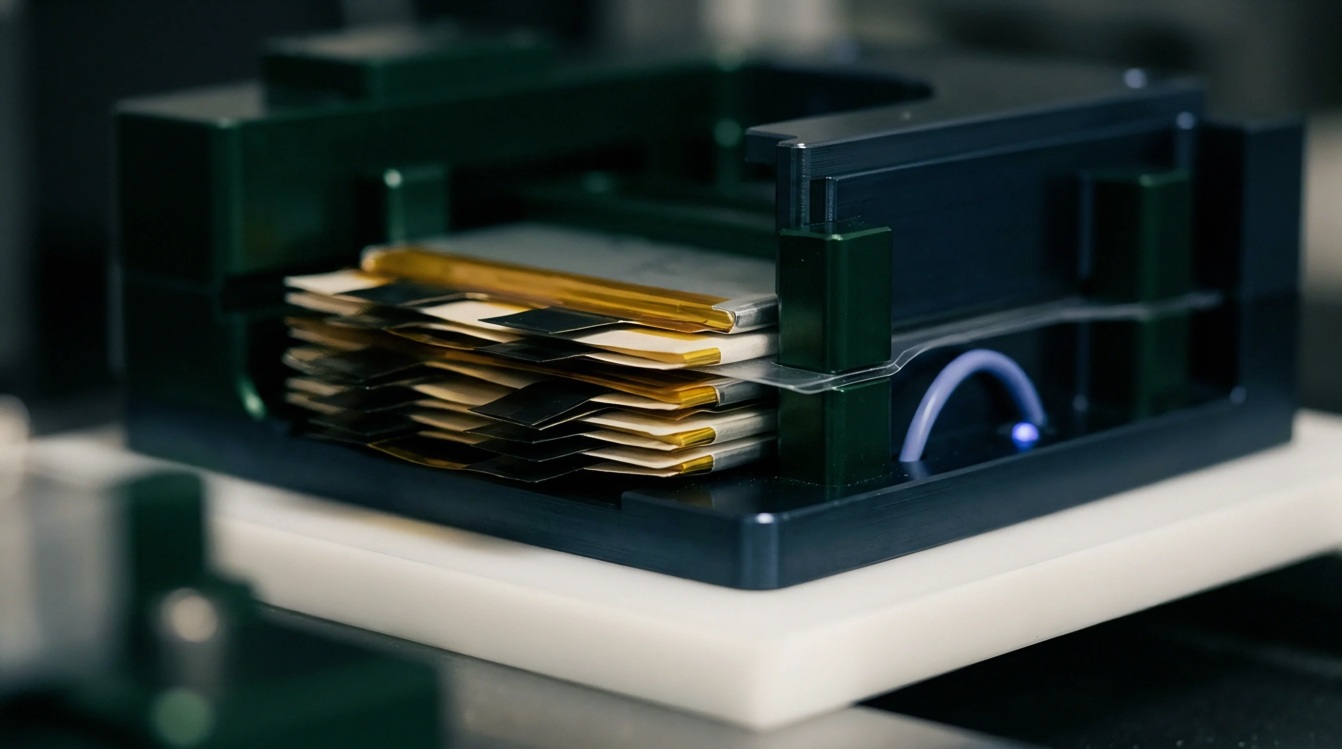
Module structures rely on mechanical compression to preserve stack alignment and make up for the friction drop caused by electrolyte wetting. Polyurethane foam pads, silicone cushions, or microcellular spring elements sit between cells or at end-plates to maintain positive compression over the swelling lifecycle.
Designing compression structures requires balancing two failure modes. Insufficient pressure allows separator displacement, layer buckling, and overhang loss during high-rate cycling. Excessive pressure crushes separator micropores, restricting ion transport, raising impedance, and accelerating localized lithium plating.
Operating pressure must stay above the threshold that stops dynamic sliding under peak expansion, but below the limit that restricts ionic conductivity.
In a pouch cell module specifying 300 mm by 100 mm cells with a wet-process ceramic-coated separator in standard carbonate electrolyte, the measured wetted static friction coefficient (mu_s) against a graphite anode is 0.22. Finite element simulation shows high-rate fast charging generates a peak localized shear force of 450 Newtons across the cell face from differential thermal expansion and anode swell. To prevent internal slip, the minimum clamp force must satisfy:
Normal Force = Lateral Shear Force / mu_s
Normal Force = 450 N / 0.22 = 2045.5 Newtons
Dividing this force by the active face area (0.03 square meters) yields a minimum operational pressure of 68.2 kPa. Factoring in microcellular foam relaxation over five years ~ assuming test data showing thirty percent force loss under continuous load at 45 degrees Celsius ~ the initial assembly pre-charge pressure scales upward:
Initial Pre-charge Pressure = Minimum Pressure / (1 – Relaxation Factor)
Initial Pre-charge Pressure = 68.2 kPa / (1 – 0.30) = 97.4 kPa
Foam selection depends on precise spring rates and resistance to permanent creep set. The table below lists performance parameters for common elastomeric buffering materials used to maintain cell compression.
| Material Grade | Density (kg/m3) | Initial Force at 25% Strain (kPa) | Stress Relaxation after 1000h at 50°C (%) | Thermal Conductivity (W/m·K) |
|---|---|---|---|---|
| Microcellular Polyurethane Foam (High Density) | 400 | 150 ± 15 | 22 ± 3 | 0.09 |
| Microcellular Polyurethane Foam (Low Density) | 240 | 70 ± 10 | 31 ± 4 | 0.06 |
| Closed-Cell Silicone Foam | 350 | 110 ± 12 | 12 ± 2 | 0.12 |
| Cross-linked Polyethylene (XLPE) Foam | 100 | 45 ± 8 | 48 ± 5 | 0.04 |
Effective integration requires establishing mechanical pressure validation rules within cell master supply agreements:
Sustained pre-charge pressure prevents separator slip without exceeding maximum allowable ionic transport resistance thresholds.
Selecting pack enclosure components requires quantitative mechanical data validated across full operating temperature bands and state-of-charge windows. Accounting for wetted friction degradation in module design protects long-term structural integrity and electrical safety.
- Initial pre-charge targets must account for worst-case wetted friction coefficients measured at maximum expected operating temperatures.
- End-plate deflection limits must restrict structural bending to less than 0.5 mm under maximum cell swelling loads.
- Foam pad thickness tolerances must stay within plus or minus five percent to prevent uneven pressure across the cell face.
- Continuous pressure monitoring during qualification testing must track force retention through simulated thermal shock and life cycling.
Under the cell supply contract annex, internal stack alignment loss exceeding 0.3 millimeters under standard clamping forces constitutes a manufacturing non-conformance, putting financial liability for recall action directly on the supplier.