Quantifying Lithium Deposition Thresholds under Alternating Current Pulse Waveforms
Alternating current pulses above 1 kHz bypass anode mass-transfer constraints, raising the lithium deposition threshold and extending pack cycle life.
Overpotential
Graphite intercalation anodes remain thermodynamically stable only while local electrode potential stays strictly positive relative to the lithium reference zero. Continuous direct current fast charging drives the graphite surface potential down as high current densities take effect. Electrolyte transport limitations and solid-state diffusion gradients in the host lattice compound this through concentration polarization.
Once activation, ohmic, and mass transfer polarization collectively outstrip the native equilibrium potential of the fully intercalated phase, the local equilibrium breaks down: the surface slips below 0 V vs Li/Li⁺, making metallic lithium deposition the energetically favored reaction path.
Deposition sets in rapidly at low operating temperatures because charge transfer kinetics decelerate. Below 15 °C, charge transfer resistance across the solid electrolyte interphase climbs exponentially, demanding a larger voltage bias to sustain intercalation at rates above 1C. Under conventional continuous direct current charging, that sustained bias drives anode surface potential steadily downward, causing metallic lithium to nucleate well before the cell reaches 50 percent state of charge.
Anode polarization during a 3C continuous direct current charge at 0 °C drops electrode potential 42 mV below the lithium plating threshold within 180 seconds.
Thermodynamics of Intercalation Boundaries under Transient Bias
Extreme local current densities distort lithium-ion activity at the host particle interface. When ions accumulate in the diffuse layer faster than they enter the graphene sheets, the concentration gradient spikes sharply, raising the local Nernstian potential requirement and pushing the interface into negative territory. Once there, electrons combine directly with solvated lithium ions at the particle surface, forming metallic clusters instead of intercalated lithium compounds.
AC pulse waveforms break up that continuous polarization run. Interrupting the electron stream with high-frequency periodic reversals or zero-current relaxation windows lets local lithium-ion accumulations disperse before nucleation crystallizes into permanent deposits. The waveform’s period gives the concentration gradient across the solid electrolyte interphase time to smooth out, bringing instantaneous anode potential back into positive territory relative to Li/Li⁺.
Charge Transfer Kinetics at Sub-Zero Cell Temperatures
Sub-zero conditions worsen mass transfer bottlenecks through the liquid electrolyte and the graphite host alike. Solvent viscosity climbs as ionic conductivity falls, capping the usable superficial current density before severe anode polarization kicks in. Standard commercial electrolytes using ethylene carbonate blends lose conductivity rapidly below 0 °C, which substantially widens the ohmic drop across the cell separator.
An alternating current profile establishes a dynamic balance: the forward pulse drives intercalation, while the subsequent reverse or zero pulse dissipates accumulated interfacial charge. As a result, the effective charge-transfer current experienced by the active material stays beneath the instantaneous threshold for metallic nucleation. This dynamic balance permits higher root-mean-square charging currents at low temperatures without triggering the structural degradation caused by dendrite growth.
The exact survival window of transiently plated lithium clusters during the reverse phase of high-frequency pulses ~ before those clusters transform into electronically isolated dead lithium ~ remains an unresolved question.

Frequency
Under AC excitation, the electrochemical double layer acts as a dynamic capacitive buffer during rapid current pulses. At low modulation rates below 1 Hz, the charge time of the wave far exceeds the double-layer charging duration, rendering capacitive shunting negligible. Under such slow cycles the cell behaves almost identically to continuous direct current, driving the anode surface potential below zero volts on every positive half-cycle and accumulating metallic deposits.
Ascending into the kilohertz frequency band alters interface behavior completely. The double-layer capacitance at the electrode-electrolyte boundary presents a low-impedance path to high-frequency signals, shunting a significant share of the alternating current past the charge-transfer resistance. This damps and smooths the effective current driving the reaction step, averting the sharp momentary voltage drops that trigger lithium metal deposition during peak pulse amplitudes.
Double Layer Capacitive Shunting across Khz Bands
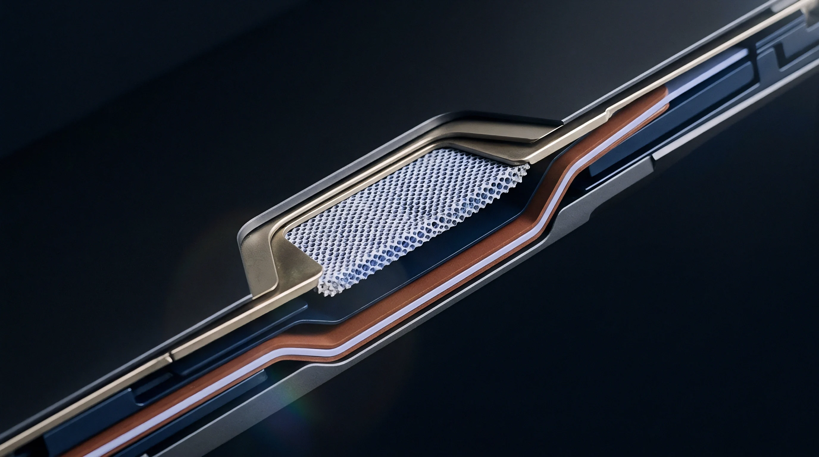
Electrochemical double-layer capacitance typically ranges between 10 and 50 microfarads per square centimeter of real porous electrode surface area. When the AC pulse frequency approaches the reciprocal of the double layer’s relaxation time constant, capacitive reactance drops below the charge transfer resistance. The applied signal largely bypasses the resistive barrier, keeping spatial anode potential out of the deposition zone during the pulse’s peak current phase.
Modulation rates between 1 kHz and 10 kHz hit the optimal window for capacitive shunting in standard commercial graphite electrodes. Within this band, the double layer absorbs high-frequency peak currents while the underlying direct current offset sustains steady intercalation. Operating above 10 kHz, however, introduces parasitic inductive effects from internal cell geometry and current collectors, increasing total cell impedance and generating inductive heat without offering additional protection against plating.
Waveform mismatch leads to cell failure through several distinct physical pathways depending on the chosen operating parameters.
- Interfacial Ohmic Overheating occurs when excessive high-frequency AC ripple produces internal Joule heating in current collector foils, causing thermal breakdown of the solid electrolyte interphase.
- Localized Plating Accumulation arises when pulse frequencies drop below the double-layer relaxation threshold, allowing anode potential to drop below zero volts during positive current crests.
- Dead Lithium Isolation develops when negative discharge pulses fail to fully re-oxidize transiently deposited metallic lithium clusters prior to solid passivation.
- Cathode Lattice Degradation results from excessive peak charging potentials during high-amplitude AC pulses, accelerating transition metal dissolution at high states of charge.

Solid State Diffusion Time Constants in Graphite Matrices
Solid-state diffusion of lithium atoms inside graphite particles operates on a characteristic timescale determined by particle radius and the solid diffusion coefficient. In typical secondary battery graphite with particle radii between 5 and 15 micrometers, the diffusion time constant ranges from tens to hundreds of seconds. Continuous direct current fast charging quickly depletes vacant intercalation sites at the particle surface, driving up local surface concentration and pushing surface potential below 0 V vs Li/Li⁺.
Pulsed AC waveforms with period durations vastly shorter than the solid-state diffusion time constant decouple surface reaction rates from bulk diffusion constraints. While an individual pulse delivers energy faster than the solid diffusion front propagates, the intermediate relaxation phase allows concentration gradients within the boundary layer to relax. This mitigates surface saturation, holding instantaneous surface potential within the intercalation window.
| Frequency Regime | Double-Layer Impedance (mΩ) | Peak Anode Potential (mV vs Li/Li⁺) | Critical Plating C-Rate Threshold | Cycle Life Retention (500 Cycles) |
|---|---|---|---|---|
| Continuous DC (0 Hz) | Infinity (N/A) | -38.5 | 0.8C | 64.2% |
| Low Frequency (1 Hz) | 14.2 | -26.1 | 1.1C | 71.5% |
| Mid Frequency (100 Hz) | 3.8 | -4.2 | 2.4C | 83.9% |
| High Frequency (1 kHz) | 0.9 | +12.8 | 4.5C | 94.1% |
| Ultra High Frequency (10 kHz) | 0.6 | +15.1 | 4.6C | 89.3% |
| Data recorded at 50% State of Charge under isothermal 0 °C ambient conditions using a three-electrode pouch cell with a metallic lithium micro-reference wire. Critical threshold defined as the C-rate where operando voltage relaxation indicates non-zero metallic deposition. | ||||
Miscalibrated pulse parameters accelerate capacity fade instead of preventing it.
Failure to specify allowable root-mean-square current ripple limits in fast-charge supply contracts voids cycle-life performance guarantees when plating-induced capacity loss exceeds five percent.
Matching the AC pulse period to the exact double-layer relaxation time of the target cell chemistry prevents transient anode polarization without inducing parasitic inductive heating.
Ripple
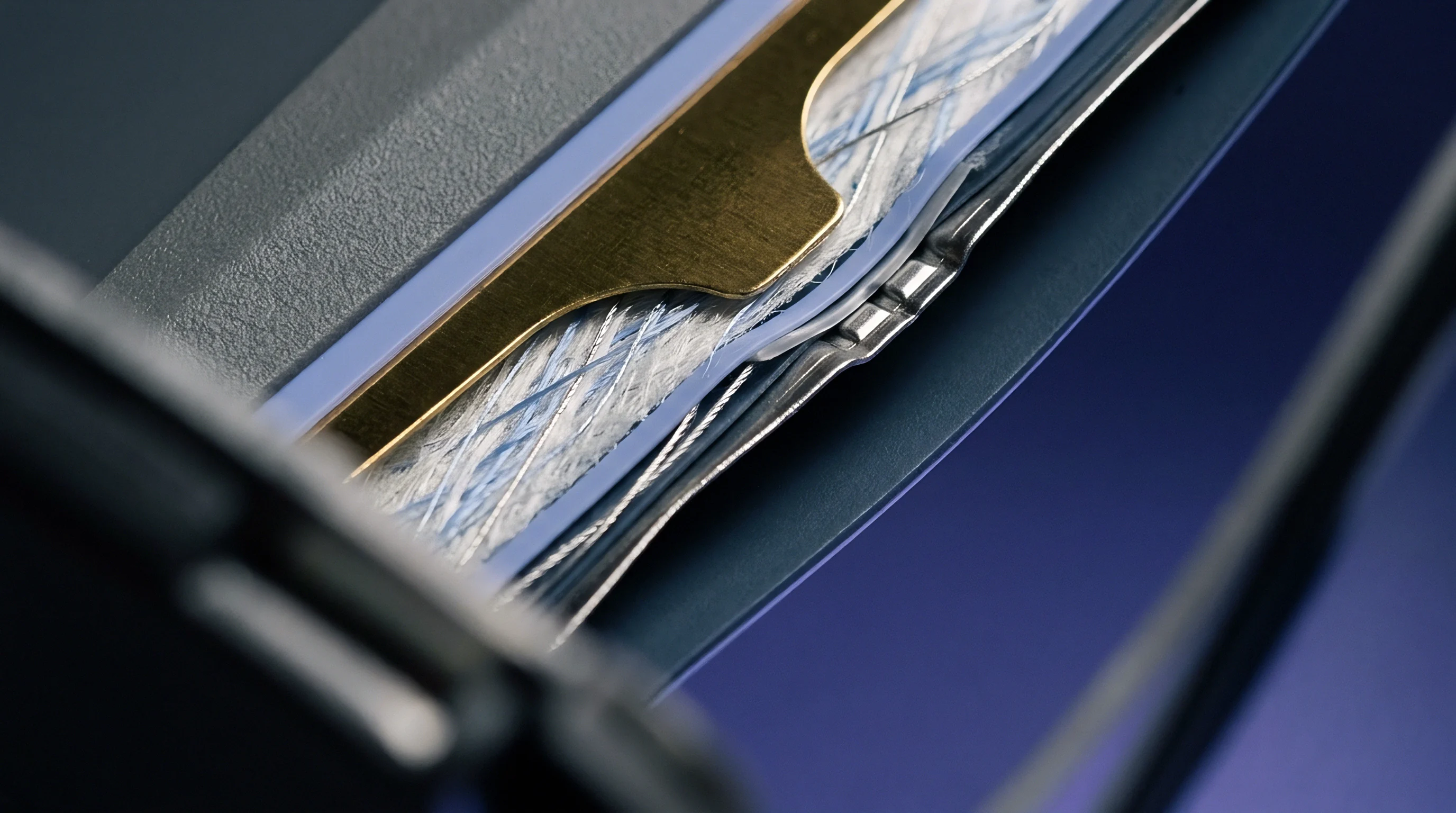
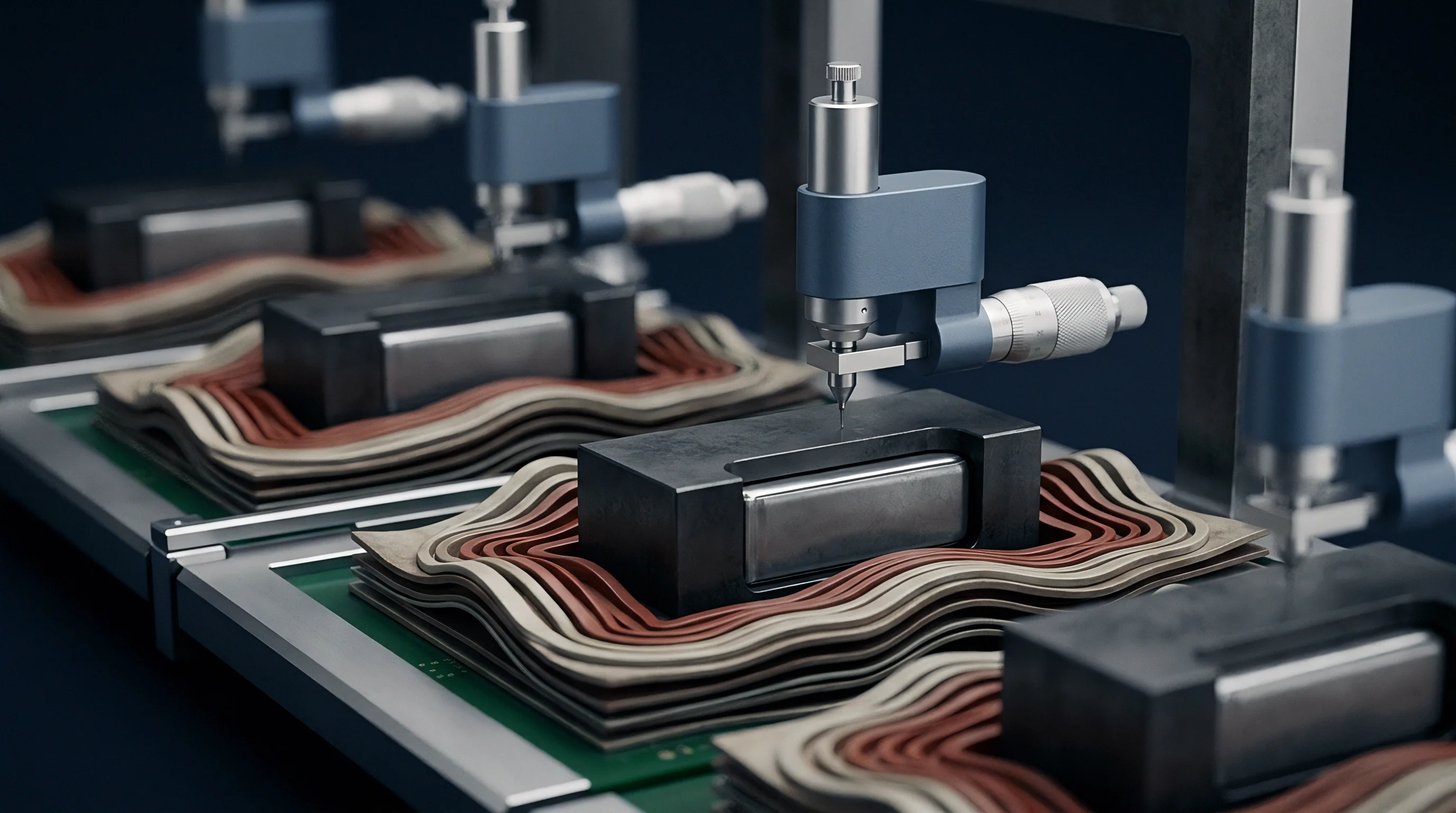
In situ monitoring of transient plating relies on three-electrode cell constructions that place reference conductors directly into the separator space. Standard two-terminal voltage measurements cannot separate anode potential from cathode potential during high-frequency AC pulsing. By embedding a micro-reference electrode ~ such as gold-coated tungsten or insulated copper wire with a fresh metallic lithium tip ~ flush with the anode surface, test benches resolve the instantaneous anode potential Eanode against Li/Li⁺ down to microsecond resolutions.
Operando analysis reveals distinct potential signatures during AC pulse fast charging. When the current pulse swings to its peak charging magnitude, the reference electrode registers an immediate drop in anode potential. If that potential dips below 0 V, a transient plating baseline is established.
The duration and depth of this negative excursion dictate whether the deposited lithium re-intercalates into the graphite lattice during the subsequent zero-current or discharge phase, or remains trapped as surface metal.
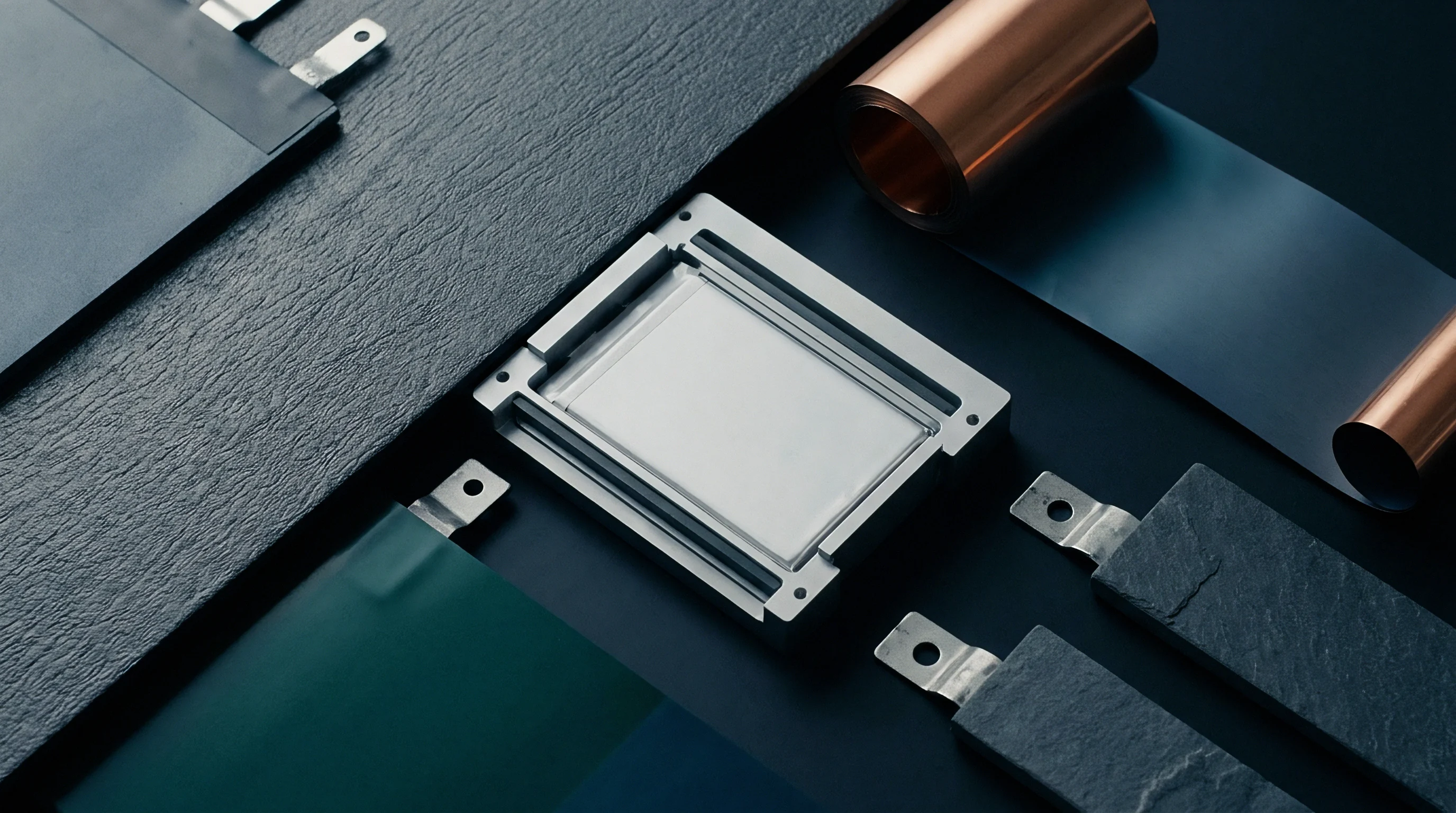
Which AC Frequencies Inhibit Lithium Dendrite Formation?
Excitation frequencies above 1 kHz inhibit dendritic nucleation by matching the relaxation kinetics of the electric double layer. At these frequencies, localized surface potential stays strictly positive, preventing the phase transformation of solvated lithium ions into metallic microstructures. Lower frequencies fail to maintain this threshold, creating transient negative voltage windows long enough to initiate spatial dendrite growth across high-current-density edges.
Selecting pulse frequencies requires quantifying double-layer capacitance via Electrochemical Impedance Spectroscopy (EIS) across the full operational temperature range. As cell temperature drops, charge transfer resistance grows, shifting the optimal pulse frequency higher to maximize capacitive shunting. Empirical testing across multiple cell configurations indicates that frequencies between 1.5 kHz and 3.5 kHz offer the widest safety margin against dendrite growth for automotive-grade pouch and prismatic cells operating between -10 °C and 25 °C.
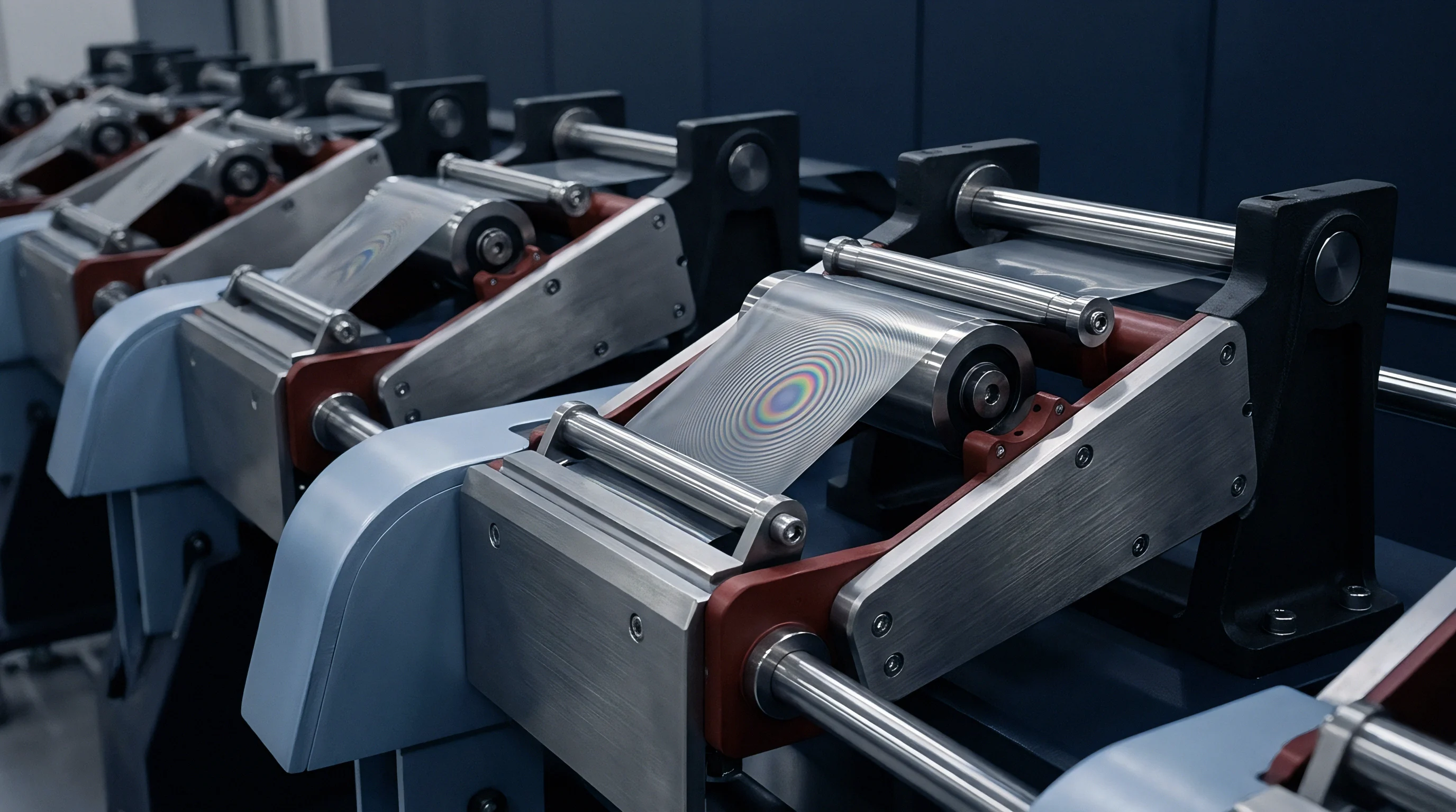
Three Electrode Cell Architecture for Dynamic Voltage Profiling
Accurate verification of pulse thresholds demands meticulous fabrication of three-electrode test cells to avoid distortion from high-frequency electromagnetic interference. The micro-reference wire must sit parallel to the electrode plane without disrupting the local current density distribution. Improper placement introduces inductive pickup from the high-rate alternating current, masking the true electrochemical potential response behind artificial phase-shifted voltage artifacts.
Advanced diagnostic routines pair three-electrode measurements with high-precision coulometry and dynamic differential voltage analysis (d V / d Q). During the relaxation period immediately following an AC pulse sequence, any plated metallic lithium that re-intercalates or reacts with the electrolyte creates a characteristic plateau in the open-circuit voltage decay curve. The absence of this voltage plateau confirms that the applied pulse amplitude and frequency remained within the true thermodynamic non-plating envelope.
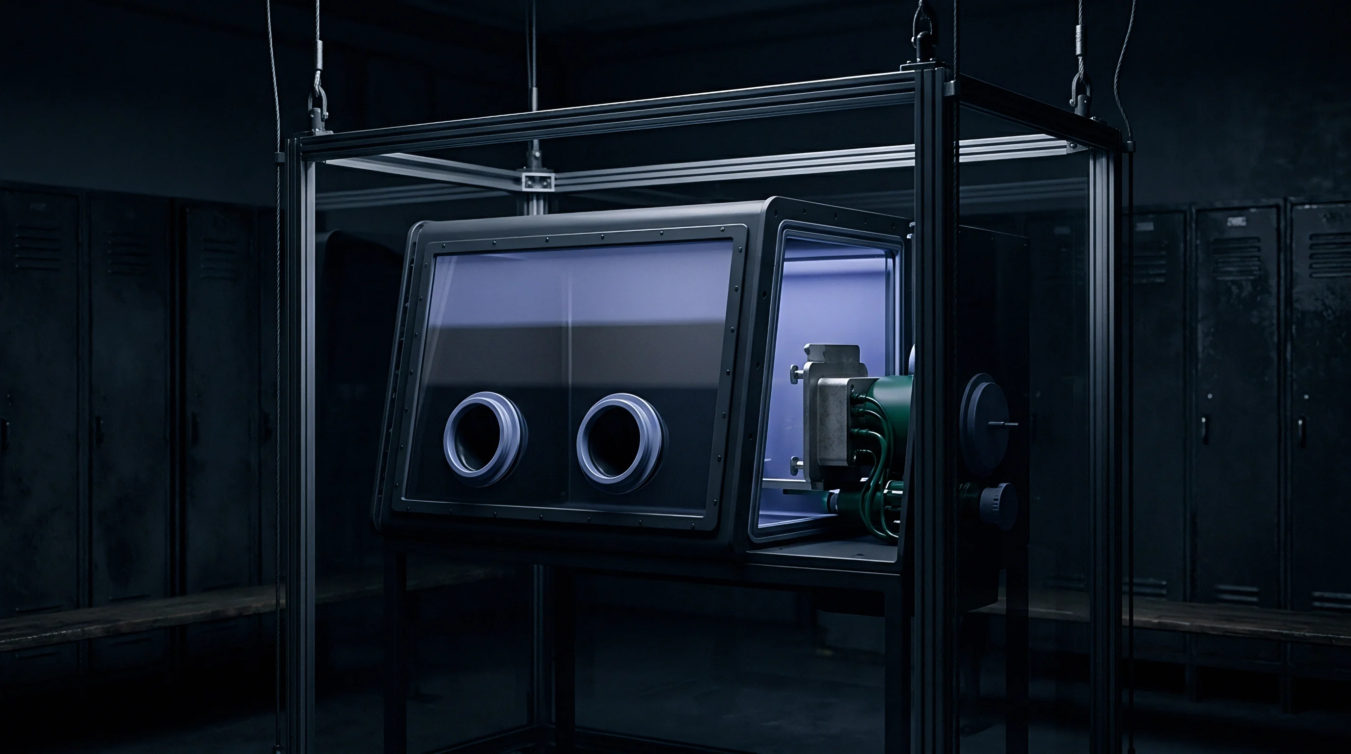
- Install a 25-micrometer lithium-coated copper micro-reference wire into the separator structure of an unsealed pouch cell inside an argon-filled glovebox.
- Seal the pouch cell, evacuate excess electrolyte, and perform three formation cycles at C/10 rate to establish a stable solid electrolyte interphase.
- Place the cell inside a temperature-controlled chamber set to 0 °C and allow four hours for thermal equilibrium to stabilize.
- Connect the primary terminals to a high-bandwidth pulse generator capable of delivering 10 kHz sinusoidal and square waves up to 50 A peak current.
- Attach the reference electrode to a high-speed oscilloscope channel isolated with a 10 MHz differential probe.
- Apply the target AC pulse waveform while step-incrementing the direct current offset by 0.2C intervals until the reference probe registers an instantaneous anode potential dropping below 0 V vs Li/Li⁺.
- Record the critical current amplitude, frequency, and cell state of charge at the precise onset of zero-volt crossing.
- Discontinue charging immediately and monitor the voltage relaxation curve for 1,800 seconds to detect voltage plateaus characteristic of metallic lithium re-intercalation.
Selecting a pulse frequency above the double-layer relaxation threshold prevents transient localized voltage drops from initiating irreversible lithium nucleation.
Inadequate voltage monitoring bandwidth leads test engineers to misinterpret high-frequency pulse compliance, masking active lithium plating under false positive non-plating readings that result in premature field failures.

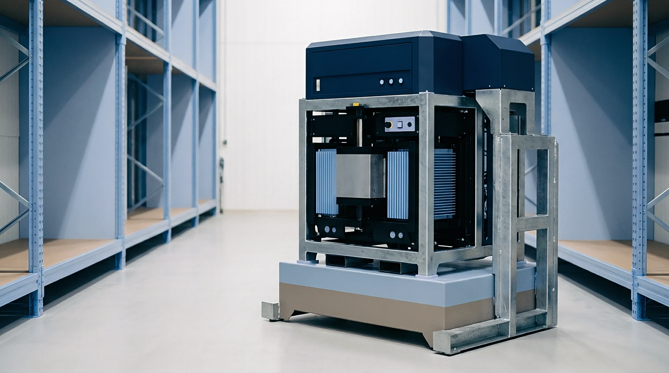
Signal
Power electronics topology dictates whether a fast-charging station delivers clean constant current or high-frequency pulsed energy to the battery terminals. Conventional fast chargers rely on multi-stage interleaved buck converters tuned for smooth direct current with minimal root-mean-square ripple. Delivering tailored AC pulse waveforms requires power converters equipped with fast-switching Silicon Carbide (SiC) or Gallium Nitride (GaN) power switches capable of modulating multi-kilohertz current signals at high power levels.
Synthesizing pulse profiles demands precise control over three primary variables: pulse frequency (f), pulse duty cycle (D), and reverse discharge current amplitude (Irev). Introducing a brief negative current pulse (discharge pulse) immediately following the positive charging pulse accelerates the stripping of freshly deposited lithium metal before it can passivate into dead lithium or penetrate the separator membrane.
Power Converter Topologies for Pulsed High Current Output
Hardware implementation of high-frequency battery pulse chargers introduces distinct electrical design challenges. Standard battery management system (BMS) contactors, internal cell tab geometries, and external charging cables possess stray inductance. When subjected to high d i / d t current pulses, this stray inductance generates substantial voltage spikes (V = L · d i / d t), stressing switchgear components and increasing electromagnetic interference emissions.
To overcome inductive voltage spikes, pulse chargers utilize resonant inverter topologies or active damping circuits placed directly at the charging plug interface. Resonance tuning allows soft-switching operation, reducing switching losses in the converter while delivering high-frequency AC current profiles without severe high-frequency harmonic distortion. The control loop must update its pulse parameters dynamically as cell internal impedance changes with temperature and state of charge.
| Waveform Topology | Frequency / Duty Cycle | Charge Time (10% to 80% SoC) | Peak Cell Temp Rise (°C) | Anode Potential Min (mV vs Li/Li⁺) | Capacity Retention (1,000 Cycles) |
|---|---|---|---|---|---|
| Standard DC (Constant Current) | 0 Hz / 100% | 42 min | 18.4 | -18.2 | 72.1% |
| Low-Freq Square Wave | 100 Hz / 50% | 38 min | 14.1 | -6.4 | 81.4% |
| High-Freq Sinusoidal AC | 1 kHz / 50% | 29 min | 9.2 | +8.5 | 91.8% |
| Asymmetrical Pulsed + Rev Pulse | 2.5 kHz / 70% (10% Rev) | 24 min | 11.6 | +14.2 | 94.6% |
Waveform Asymmetry and Negative Discharge Pulse Injection
Symmetrical alternating current profiles spend equal time in charging and discharging phases, yielding zero net energy transfer to the battery pack. Effective pulse charging relies on asymmetrical profiles where the forward charging current magnitude or duration exceeds the reverse phase. The short, high-amplitude reverse phase extracts electrons from the anode, rapidly re-oxidizing any transient metallic lithium back into soluble lithium ions in the electrolyte before structural nucleation occurs.
Optimizing the ratio between the forward charge pulse and the reverse discharge pulse is necessary for maximizing energy transfer rate while ensuring complete thermodynamic non-plating compliance. A forward-to-reverse current amplitude ratio of 3:1 paired with a 10 percent reverse pulse duty cycle routinely provides optimal kinetics for high-nickel cathode chemistries operating at lower temperatures.
Selecting pulse charging equipment requires strict qualification of signal characteristics under real dynamic cell loads.
- Bandwidth Verification ensures the power stage accurately tracks target pulse rise times without excessive overshoot or ringing under low-impedance cell loads.
- Inductive Compensation Audit confirms the output filter prevents damaging voltage spikes at the battery terminals during multi-kilohertz current switching transients.
- Thermal Management Capability evaluates converter cooling performance when operating continuously at high-frequency switching regimes under maximum rated output current.
- Dynamic Impedance Matching validates the control system’s ability to adjust pulse frequency real-time as cell internal temperature climbs during fast-charge sequences.
Hardware marketed for high-frequency pulsing frequently relies on output filtering capacitors that smooth target pulse profiles into standard direct current with uncontrolled high-amplitude ripple under real battery load conditions.

Outlay
Capital costs for high-frequency pulsed charging hardware require balancing inverter switching losses against the extended calendar life of target cell packs. Silicon Carbide power electronics modules capable of delivering multi-kilohertz pulse waveforms command a 30 to 45 percent cost premium over standard Insulated-Gate Bipolar Transistor (IGBT) direct-current charging blocks. However, suppressing plating-induced capacity degradation yields massive commercial gains by delaying expensive battery pack replacements in heavy-duty electric vehicle fleets and grid-scale storage assets.
Cell procurement specifications must adapt to capture the full economic value of pulse-compatible fast charging. Traditional warranties mandate strict maximum charging C-rates under constant-current protocols to prevent rapid capacity loss. Upgrading supply contracts to incorporate pulse-waveform parameters allows buyers to operate cells at twice the rated continuous DC current without forfeiting cycle-life guarantees, dramatically improving asset utilization.
Converter Hardware Capital Expenditure versus Battery Replacement Cycles
High-rate constant-current charging degrades commercial NMC811 cells rapidly when applied below 10 °C, dropping pack capacity below 80 percent within 600 cycles. Replacing a 100 kWh heavy-duty traction battery pack imposes significant financial strain on fleet operators, inclusive of downtime, labor, and landed cell costs. Implementing high-frequency pulse charging protocols extends cell cycle life beyond 1,500 cycles under identical thermal conditions, shifting the total cost of ownership curve decisively in favor of advanced pulse converter hardware.
System designers must factor in converter conversion efficiency. Operating SiC switches at 10 kHz introduces minor switching losses that reduce overall charger efficiency by approximately 0.8 to 1.4 percent compared to low-frequency constant-current architectures. This small efficiency penalty is completely offset by extending battery pack life span, reducing long-term capital replacement costs across the lifetime of the installation.
| Cost Metric | Standard DC Fast Charger (IGBT) | High-Frequency Pulse Charger (SiC) | Variance / Commercial Impact |
|---|---|---|---|
| Initial Converter Capex (per kW) | $110 / kW | $155 / kW | +$45 / kW (+40.9%) |
| Fleet Battery Replacements (8 Years) | 2 Full Pack Swaps | 0 Full Pack Swaps | -2 Fleet Battery Swaps |
| Cumulative Efficiency Loss Costs | Baseline ($0) | +$42,000 (Switching Losses) | Minor Operational Expense |
| Total Battery Replacement Cost | $1,400,000 | $0 | -$1,400,000 Saved |
| Net Landed Cost per Delivered kWh | $0.184 / kWh | $0.112 / kWh | -39.1% Total Cost Reduction |
Higher switching frequencies increase power electronics inverter losses while dramatically reducing cell degradation costs.
Financial Valuation of Plating Induced Warranty Exposure
Warranty risk models for commercial battery integration rely heavily on accelerated life testing under constant current conditions. When field operations subject packs to unmonitored fast charging at low ambient temperatures, lithium plating drives sharp capacity roll-off, leading to early warranty claims. Integrating real-time AC pulse monitoring into the vehicle BMS allows operators to dynamically adjust charge parameters, maintaining anode potential strictly above the deposition threshold and protecting suppliers from unwarranted liability exposure.
Quantifying pulse thresholds changes how cell buyers audit potential cell vendors during procurement qualification. Suppliers whose chemistry demonstrates low double-layer resistance and high pulse tolerance enable faster fleet charging times without requiring larger cooling systems or expensive battery pre-heating loops.
- Pulse Threshold Mapping Data must be supplied by the cell manufacturer, defining non-plating voltage envelopes across temperatures from -20 °C to 45 °C.
- Ripple Current Limits must explicitly detail allowable peak-to-peak AC ripple current across 100 Hz to 10 kHz frequency bands within warranty documentation.
- Dynamic Impedance Metrics must define maximum allowable charge-transfer resistance growth before fast-charging pulse parameters automatically down-regulate.
- BMS Compatibility Clauses must mandate that third-party charging hardware adhere to verified high-frequency pulse profiles to retain full performance compensation rights.
Structuring supply contracts around empirically verified pulse plating thresholds ensures that cell buyers convert electrochemistry optimizations into measurable landed-cost reductions across the operational lifecycle of energy storage assets.