Quantifying Non-Destructive Sub-Micron Fibril Creep Dynamics under Long-Term Cell Stack Compression
Non-destructive ultrasonic time-of-flight isolates separator fibril creep from cell swelling, quantifying sub-micron pore collapse under stack compression.
Stack
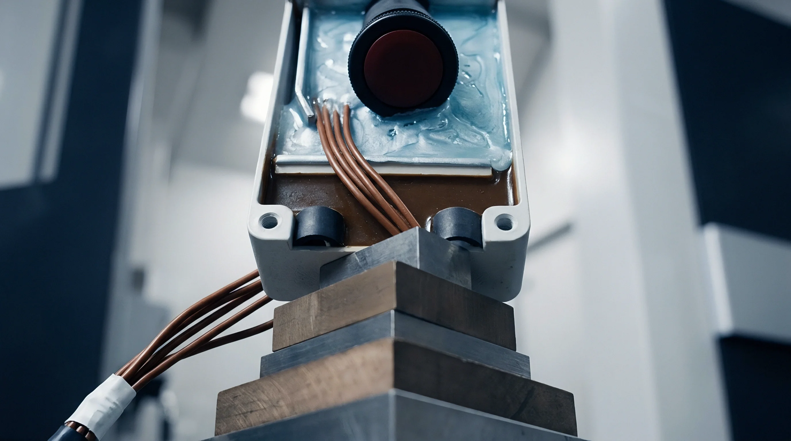
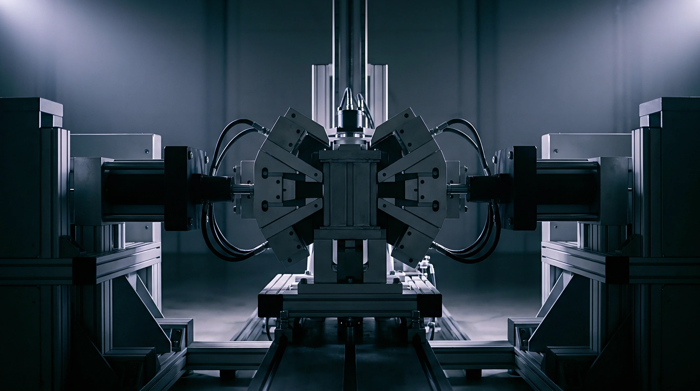
Module mechanical retention determines cell longevity well before electrochemical cycling ever starts. Clamping twenty-four 150 Ah prismatic cells between aluminum end-plates compresses the active electrode coatings, current collectors, and microporous polymer separator films into a dense composite stack. Assembly jigs torque the tie-rods to establish baseline interface pressures between 0.30 and 0.80 megapascals.
While that load closes contact gaps, limits lateral pouch breathing, and prevents layers from delaminating during intercalation, the separator trapped inside each jelly-roll absorbs the brunt of the sustained normal stress.
Polyolefin separators rely on sub-micron fibrils running between micro-scale polymer nodes. Under static module tension, this fibrillar network creeps rather than behaving like an ideal elastic spring, undergoing continuous, time-dependent viscoelastic deformation. Machine-direction fibrils measure twenty to eighty nanometers across, bridging void openings of thirty to fifty nanometers.
Sustained compression forces these polymer bridges to bend, slip, and reorient transversely. As pore throats narrow, ionic pathways through the liquid electrolyte constrict, driving up MacMullin numbers and increasing internal cell resistance.
Sustained platen force flattens microporous polymer networks before electrochemical cycling registers a measurable shift in cell polarization.
Mechanical drawings frequently treat clamping force as a simple tolerance band, commonly 0.50 megapascals plus or minus 0.05 megapascals at beginning of life, ignoring how separators actually behave over time. Constant displacement fixtures impose rigid boundaries, so that when graphite anodes expand twelve percent at full state of charge, structural swelling converts directly into rising normal stress. Constant-force spring packs avoid that pressure surge, but allow the outer module dimensions to drift over years of service.
Either way, the separator fibrils end up driven toward irreversible structural collapse.
Thinner membranes yield under substantially lower loads. A twelve-micron wet-process polyethylene separator follows completely different creep kinetics than a twenty-micron dry-process polypropylene web. Specifying cell compression without modeling that yield behavior risks electrolyte dry-out, premature starvation, and lithium dendrite growth across pinched zones.
Establishing uniform mechanical displacement across the cell face at the start protects the porous web far better than trying to balance spring tension once cycling is underway.
Fibril
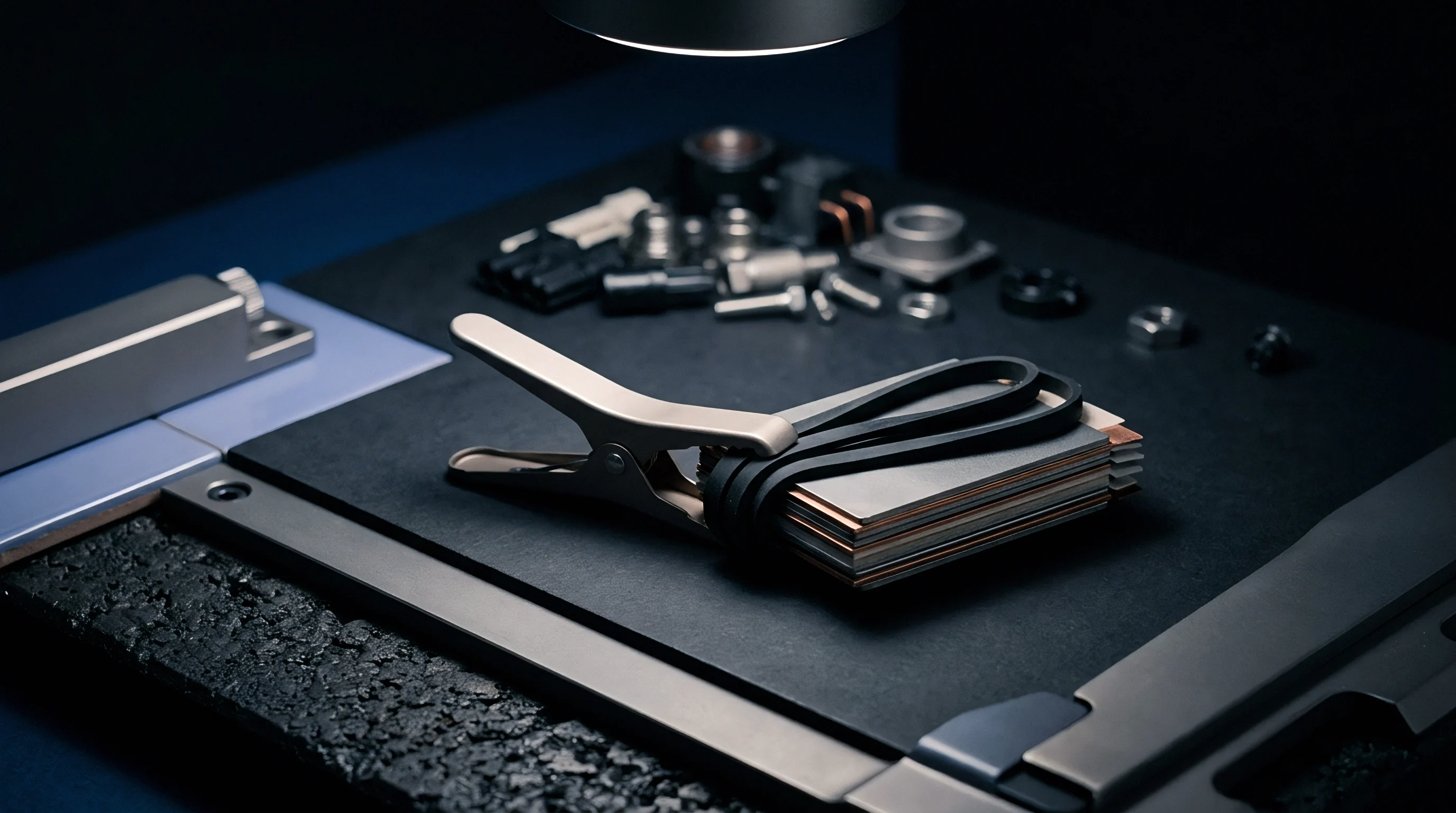
Polymer morphology governs how sub-micron fibrils handle mechanical stack stress. Dry-process separators, made by extrusion, annealing, and uniaxial stretching, rely on row-nucleated lamellar structures with parallel fibrils spanning slit-like micropores. Wet-process membranes, formed by blending ultra-high molecular weight polyethylene with paraffin oil before biaxial stretching, yield an isotropic, web-like mesh.
Under sustained vertical pack loads, the two architectures behave very differently.
What Triggers Accelerated Creep under Compression?
Elevated temperatures and localized stress concentrations work together to accelerate polymer slip. Anode overhangs, edge burrs, and ceramic coating particles concentrate clamping forces onto micro-scale contact peaks. While nominal stack pressure might sit at 0.50 megapascals, local asperities frequently see loads above 4.0 megapascals.
Between 35 and 50 degrees Celsius, polyolefin chains gain enough mobility to enter secondary creep, permanently necking down the fibrils until they lose structural stiffness.
Under sustained stress, structural breakdown across the separator occurs through several distinct physical mechanisms:
- Transverse fibril buckling develops when lateral compressive vectors deflect elongated polymer bridges sideways, narrowing active pore throat diameters by fifteen to forty percent.
- Lamellar node slippage sets in once mechanical stress passes the yield point of the amorphous tie molecules linking crystalline lamellae, thinning the membrane irreversibly.
- Ceramic particulate indentation pushes sub-micron aluminum oxide or boehmite particles from surface coatings into the soft polyethylene substrate, shutting down local ionic pathways.
- Pin-hole precursor shearing occurs along boundary zones where mismatch in expansion between active material coatings and metallic current collectors tears individual fibril bundles.
Biaxial wet-process polyethylene membranes lose 14 percent of original thickness under a constant 0.8 megapascal load at 45 degrees Celsius over two thousand hours.
When fibrils creep into open voids, separator tortuosity rises from an uncompressed baseline of 1.8 to more than 3.5. That geometric constriction restricts lithium ion flux during high-rate charging, driving up local overpotentials until metallic lithium deposits on the graphite surface directly across from compacted zones. Late-life capacity loss is frequently diagnosed as active material wear rather than mechanical thinning of the separator membrane under structural preload.
Acoustics
Ultrasonic inspection offers a practical, non-destructive method for tracking sub-micron compaction inside hermetically sealed cells. Longitudinal sound waves travel through the stack at velocities set by the density and elastic modulus of each layer. A piezoelectric transducer on one face sends high-frequency pulses between 1.0 and 5.0 megahertz through the casing wall, across alternating layers of copper, graphite, separator, lithium nickel manganese cobalt oxide, and aluminum, to a receiving transducer on the opposite side.
Does Acoustic Velocity Resolve Localized Thinning?
Acoustic velocity changes as the polymer fibrils flatten within the electrolyte. Sound moves relatively slowly through an uncompressed separator because the liquid in the pores has a low bulk stiffness compared to crystalline polymer. As clamping pressure forces out electrolyte and packs the fibrils together, the separator’s effective compressive modulus increases while its thickness drops, shortening time-of-flight.
Across a typical fifty-layer pouch cell, a five percent loss in separator thickness shortens transit time by twelve to twenty-eight nanoseconds.
Resolving sub-micron displacement from acoustic time-of-flight requires a structured measurement routine:
- Baseline acoustic calibration measures initial wave velocity and amplitude through the fresh cell stack immediately after wetting and formation cycling under controlled 0.30 megapascal clamping.
- Thermal stabilization tracking holds the cell at an isothermal 25.0 degrees Celsius, plus or minus 0.2 degrees, to rule out acoustic velocity drift caused by changes in electrolyte viscosity.
- Time-domain cross-correlation evaluates successive wave packets over hundreds of operating hours, tracking nanosecond-level advances alongside signal attenuation.
- Inversion modulus reconstruction translates measured shifts in time-of-flight into absolute polymer strain, separating reversible electrochemical swelling from permanent fibril creep.
Acoustic waves traverse compacted separator sub-layers faster because collapsed pore volumes eliminate acoustic impedance mismatches between the electrolyte and polymer fibrils.
Tracking acoustic attenuation complements time-of-flight data. As fibrils creep and pack together, scattering at the polymer-liquid interfaces drops, changing the frequency-dependent attenuation coefficient. Combining velocity and damping measurements helps separate fibril compaction from active material aging, solid electrolyte interphase growth, or outgassing.
Still, separating sub-micron fibril yield from gas bubble formation in high-nickel pouch cells during fast charging remains difficult over extended field service.
Pore
Assessing fibril creep requires tracking how void fraction and ionic pathways degrade together over operating life. In a laboratory, teardowns paired with mercury intrusion porosimetry or cryo-focused ion beam scanning electron microscopy can verify pore collapse directly. In the field, monitoring pore condition depends on combining electrochemical impedance spectroscopy with precise load cell data.
As porosity drops, electrolyte resistance climbs, shifting the high-frequency ohmic intercept upward on a Nyquist plot.
Though electrolyte wetting delays signal transmission, the MacMullin number itself relates the electrical resistivity of an electrolyte-filled separator to the bulk resistivity of the liquid. For an uncompressed nine-micron polyethylene separator, baseline MacMullin numbers typically run from 4.0 to 6.5 at an initial porosity of forty percent. When sustained stack pressure forces porosity down toward twenty-five percent, the MacMullin number climbs above 11.0, effectively tripling the ionic path length and inducing severe concentration overpotentials during fast charging.
| Separator Base Polymer | Process Type | Applied Load (MPa) | Duration (Hours) | Thickness Loss (Percent) | Porosity Shift (Percent) | MacMullin Number Shift |
|---|---|---|---|---|---|---|
| UHMWPE (12 µm) | Wet Biaxial | 0.30 | 1000 | 3.8 ± 0.4 | 41.2 to 38.6 | 4.8 to 5.4 |
| UHMWPE (12 µm) | Wet Biaxial | 0.80 | 1000 | 11.2 ± 0.8 | 41.2 to 32.1 | 4.8 to 8.2 |
| UHMWPE (12 µm) | Wet Biaxial | 1.20 | 1000 | 17.4 ± 1.1 | 41.2 to 26.4 | 4.8 to 11.6 |
| PP (16 µm) | Dry Uniaxial | 0.80 | 1000 | 14.6 ± 0.9 | 46.0 to 34.2 | 5.2 to 9.8 |
| PP/PE/PP (20 µm) | Dry Trilayer | 0.80 | 1000 | 12.8 ± 0.7 | 39.5 to 30.8 | 6.1 to 10.4 |
The cumulative effect shows up clearly in pack-level calculations. Take a 100 kilowatt-hour commercial energy storage module built with twenty-four 3.2-volt, 100 Ah prismatic cells held in a rigid end-plate fixture at an initial thickness of 54.00 millimeters per cell. At a continuous 40 degrees Celsius and an average state-of-charge of sixty percent, the twelve-micron separator layers lose an average of 1.44 microns across twenty-six double-layer wraps in each cell over 3000 operating hours.
That amounts to 37.4 microns of separator loss per cell. In a rigid enclosure where aluminum tie-rods do not yield, active material expansion fills this void, pushing peak stack pressure from an initial 0.40 megapascals to 1.35 megapascals at full charge.
As creep diminishes separator dielectric strength, thinning fibrils and flattened pores cause puncture resistance to drop sharply. The force required to push a 1.0-millimeter diameter pin through the compressed membrane falls twenty-five to forty percent compared to pristine stock. That loss leaves little margin against rough electrode coatings, slitting burrs on current collectors, or isolated lithium particles building up at anode edges.
Ignoring pore collapse invites localized plating, premature impedance rise, and outright cell failure during warranty evaluations.
Retainer
Module hardware sets the mechanical boundary conditions that either limit or accelerate fibril creep. End-plates, tension bands, side channels, and compression pads dictate whether cells operate under constant stress, constant displacement, or non-linear compliance. Using rigid aluminum end-plates tied together with steel rods imposes a constant displacement boundary.
Electrode breathing during charge spikes internal pressure, speeding up visco-plastic flow in the fibrils; when the cells discharge, contact pressure drops below baseline levels, encouraging layers to delaminate.
Placing elastomeric compression pads between cells cushions against destructive pressure spikes. Polyurethane microcellular foams, silicone sponges, and mechanical springs absorb electrochemical swelling while keeping adequate seating force on the separator web. Foam selection introduces its own relaxation risks, however: if the foam loses tension faster than the separator creeps, the pack sheds its preload over three to five years, causing electrode contact loss and high thermal resistance against cooling plates.
| Retention Mechanism | Compliance Behavior | Beginning of Life Pressure (MPa) | End of Life Peak Pressure (MPa) | Separator Thickness Loss Rate | Tooling and Part Cost Adder |
|---|---|---|---|---|---|
| Solid Tie-Rod / Rigid Plate | Near-zero compliance | 0.30 ± 0.05 | 1.80 ± 0.25 | High (0.8 nm/kh) | Baseline |
| Elastomeric Microcellular Foam | Non-linear progressive | 0.35 ± 0.05 | 0.75 ± 0.10 | Moderate (0.3 nm/kh) | $1.80 to $3.20 per cell |
| Wavy Spring Pack System | Linear constant force | 0.40 ± 0.02 | 0.55 ± 0.05 | Low (0.1 nm/kh) | $4.50 to $7.00 per cell |
| Pre-tensioned Composite Straps | Viscoelastic relaxation | 0.50 ± 0.08 | 0.90 ± 0.15 | Moderate (0.4 nm/kh) | $0.90 to $1.60 per cell |
Finite element modeling shows that end-plate bowing concentrates contact pressure near the corners and edges, creating steep stress gradients across the cell face. Under a nominal 0.50 megapascal load, a standard eight-millimeter aluminum end-plate bows outward by 0.20 to 0.45 millimeters at its center. Cells in the middle experience low normal force, while those nearest the peripheral tie-rods see three times the design pressure.
This imbalance drives uneven fibril creep throughout the pack: outer cells suffer pore collapse and lithium plating, while inner cells form contact gaps and thermal hot spots.
Tooling fixtures tend to enforce rigid mechanical boundaries. While aerospace composites rely on fasteners matched for thermal expansion to maintain clamping force across temperature swings, automotive battery packs rarely include such hardware because of tooling budgets and tact time constraints. The financial risk falls along the commercial boundary between the cell supplier and the pack integrator: if pack clamping lets internal pressure rise past 1.2 megapascals, cycle life warranties are voided on the basis of separator pore collapse.
Incorporating a mandatory mechanical relaxation clause under IEC 62660-3 obligates the integrator to demonstrate stable clamping force over three thousand operating hours prior to lot acceptance.