Separator Swelling Kinetics in Lithium Battery Electrolytes
Polyolefin separators expand in electrolyte under thermal exposure, converting swelling strain into internal stack pressure that alters transport resistance.

Pore
Microporous polyolefin membranes experience distinct dimensional changes when immersed in non-aqueous battery electrolytes. Polymer crystallites within polyethylene and polypropylene matrices remain rigid, but amorphous domains absorb organic liquid molecules. Liquid uptake expands amorphous regions, forcing microfibrils apart and increasing total membrane volume.
Baseline thickness changes occur rapidly upon initial wetting, followed by logarithmic swelling kinetics over extended thermal exposure.
Z-axis expansion dominates overall volume change due to the anisotropic orientation of polymer chains produced during dry stretching or wet phase-inversion manufacturing processes. Machine-direction orientation aligns molecular backbones parallel to the film plane, constraining longitudinal growth while permitting vertical swelling. Transverse expansion stays minimal under isotropic thermal conditions.
Dry thickness measures differ markedly from fully saturated thickness dimensions after twenty-four hours of electrolyte submersion.

Absorption Dynamics
Solvent molecules penetrate amorphous polymer gaps through passive diffusion. Linear carbonates move rapidly into the polymer structure, driving early volumetric growth. Temperature accelerates solvent flux.
Higher temperatures increase polymer chain mobility, expanding the equilibrium swelling capacity of the separator film. Dynamic mechanical analysis shows a distinct decrease in glass transition temperature as liquid uptake plasticizes the polyolefin matrix.
Consider a fifty-layer pouch cell utilizing a sixteen-micrometer wet-process polyethylene membrane. Dry separator thickness equals exactly 0.800 millimeters across the active jellyroll stack. Exposure to an organic carbonate mixture generates a four-point-five percent Z-axis swelling strain within forty-eight hours at twenty-five degrees Celsius.
Total separator thickness increases by 0.036 millimeters, adding direct mechanical displacement against the outer cell packaging before any electrochemical formation cycling occurs.
Saturated polyethylene films exhibit a four-point-five percent Z-axis thickness expansion after forty-eight hours at twenty-five degrees Celsius.
Unconstrained membrane expansion alters internal void structure, expanding average throat diameters while reducing total tortuosity. Saturated films reach dimensional equilibrium when elastic recovery forces within crystalline tie-molecules balance the osmotic swelling pressure exerted by absorbed liquid. This thermodynamic equilibrium determines the permanent wet thickness of the separator inside an active cell.


Solvent
Chemical composition dictates the rate and magnitude of polymer matrix swell. Cyclic carbonates like ethylene carbonate and propylene carbonate possess high dielectric constants and strong molecular dipoles, yet their bulky ring structures impede rapid penetration into dense polymer networks. Linear carbonates, including dimethyl carbonate, ethyl methyl carbonate, and diethyl carbonate, exhibit lower viscosity and smaller kinetic diameters, enabling faster diffusion into amorphous polyethylene regions.
Electrolyte Formulations
Fluorinated additives further modify swell kinetics. Fluoroethylene carbonate and difluoroethylene carbonate alter interfacial tension between the liquid phase and polyolefin pore walls, altering localized uptake rates. Salt concentration influences solvent activity; higher lithium hexafluorophosphate concentrations slightly reduce equilibrium polymer swelling by binding free solvent molecules into lithium solvation sheaths.
| Electrolyte System | Separator Substrate | Z-Axis Swell at 25 °C (%) | Z-Axis Swell at 60 °C (%) | Equilibrium Time (h) |
|---|---|---|---|---|
| 1.0M LiPF6 EC:DMC (1:1) | Single-layer PE (12 µm) | 3.8 | 6.2 | 18 |
| 1.0M LiPF6 EC:EMC:DEC (1:1:1) | Single-layer PE (12 µm) | 4.2 | 7.1 | 14 |
| 1.0M LiPF6 EC:EMC (3:7) + 2% FEC | Trilayer PP/PE/PP (16 µm) | 2.9 | 4.8 | 22 |
| 1.2M LiPF6 EMC:DMC (1:1) | Ceramic-coated PE (14 µm) | 3.1 | 5.4 | 16 |
Activation energy for solvent uptake varies according to polymer crystallinity. High-density polyethylene demonstrates greater resistance to solvent penetration than low-density formulations due to tight crystalline packing. Elevated storage temperatures decrease liquid viscosity, speeding up saturated balance timing and maximizing cross-sectional growth across all polyolefin grades.
Substrate suppliers frequently state that baseline film specifications apply exclusively to dry material before fluid wetting. Material datasheets report mechanical tolerances tested strictly under ambient dry conditions, leaving cell integration teams to calculate wet dimensional growth independently during format design.

Strain
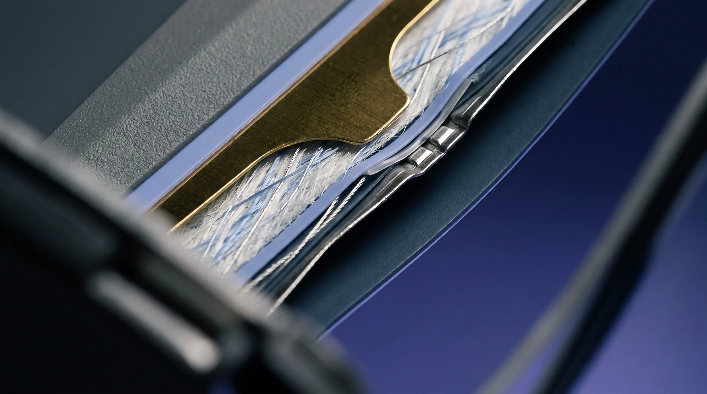
Volumetric expansion of the separator within a fixed cell housing creates internal mechanical stress. Stack pressure rises quickly. When cell enclosures prevent outer dimensional movement, separator swelling converts into compressive stress across the active electrode interfaces.
Mechanical constraint alters the pore geometry, forcing swollen amorphous polymer regions into vacant microvoids.
Can Polyolefin Blends Mitigate Orthogonal Creep?
Blends containing both polypropylene and polyethylene react unevenly to multi-axial mechanical stress under wet conditions. Polypropylene maintains higher elastic modulus when exposed to organic solvents, offering structural resistance against transverse creep. Polyethylene layers undergo plasticization, allowing gradual stress relaxation under sustained internal stack pressure.
Long-term mechanical stability depends on balancing elastic recovery with plastic creep across operational temperature ranges. Wet tensile strength drops noticeably compared to dry baseline metrics.
- Initial Wetting Phase Liquid absorption causes rapid Z-axis membrane expansion within the cell stack.
- Pressure Accumulation External housing constraint converts thickness growth into compressive internal stack stress.
- Pore Neck Compression Sustained mechanical load forces plasticized amorphous polymers into open pore structures.
- Modulus Degradation Continuous electrolyte contact reduces polymer yield strength, accelerating localized creep under cycle loads.
Internal stack pressure exceeding two megapascals accelerates separator pore collapse in plasticized wet films.
Ignoring wet stress relaxation during stack design leads to permanent separator compression, premature electrolyte dry-out, and localized lithium plating across high-utilization electrode zones.
Impedance
Ion transport through microporous membranes depends directly on internal void volume and channel tortuosity. Liquid absorption alters these internal microstructures, modifying ionic conductivity across the separator thickness. Unconstrained swelling increases pore throat dimensions, initially lowering ion movement resistance.
Constrained swelling within hard-case battery enclosures produces the opposite effect by squeezing liquid out of compressed microvoids.

Transport Properties
MacMullin number quantifies the relative resistance of an electrolyte-saturated separator compared to bulk liquid electrolyte. Baseline dry separators saturated under zero pressure exhibit typical MacMullin values between 8.0 and 10.0. Mechanical compression from constrained volumetric growth raises the MacMullin number above 14.0, restricting ionic transport pathways.
Pore collapse cuts conductivity. As compressed polymer walls bulge into open voids, effective porosity decreases while channel tortuosity increases. Higher effective resistance promotes concentrated current density distributions across active material faces.
MacMullin numbers above fourteen indicate severe pore neck constriction within compressed wet separators.
Thicker separators damp expansion forces, yet their extended transport path length inherently increases bulk cell impedance. Balancing mechanical cushion against ionic resistance remains a central challenge in high-rate cell construction. Dynamic impedance measurements during wetting trials show transient resistance spikes before chemical saturation achieves ionic transport stabilization.
Whether non-uniform separator compression can be completely compensated by optimizing initial electrolyte fill volumes remains an open engineering question in high-density cell manufacturing.


Tolerance
Battery packaging architectures respond differently to internal separator growth. Pouch cell formats allow soft outer walls to flex, relieving internal stack stress through external thickness enlargement. Prismatic metal cases enforce rigid boundaries, converting separator growth directly into internal pressure rise against wall faces.
Cylindrical designs distribute radial expansion stresses inward toward the central mandrel void.
Format Considerations
Jellyroll tightness determines initial mechanical clearance. Over-tight winding leaves zero allowance for wet film growth, resulting in core buckling and tab displacement upon electrolyte injection. Loose winding permits initial film expansion without structural deformation, though excess spacing risks jellyroll movement under external vibration.
| Cell Format | Typical Housing | Internal Stack Constraint | Swelling Accommodation Mechanism | Risk of Over-Constraint |
|---|---|---|---|---|
| Pouch 60 Ah | Aluminum Laminate Film | Low (0.1 to 0.3 MPa) | External thickness growth (pouch bulge) | Gas pouch seal rupture |
| Prismatic 280 Ah | Aluminum Hard Case (3000-series) | High (1.0 to 2.5 MPa) | Compressible side foam buffers | Case wall deflection and cell swelling |
| Cylindrical 21700 | Nickel-Plated Steel Can | Very High (> 3.0 MPa) | Inward radial creep into central core | Internal tab shearing and core buckling |
Ceramic coatings on polyolefin substrates alter mechanical tolerance requirements. Alumina or silica particle coatings prevent matrix compression, preserving open pore structures even under high internal stack loads. Ceramic layers add non-swelling dead mass, increasing dry film thickness without contributing to fluid absorption strain.
A useful rule of thumb dictates allocating internal enclosure volume clearance equal to twice the maximum predicted free-swelling Z-axis membrane displacement.

Contract
Cell procurement specifications require precise verification protocols for wet separator metrics. Procurement teams verify film properties through standardized laboratory testing before approving volume production lots. Testing protocols mandate measuring dimensional growth, fluid retention, and wet mechanical strength across controlled thermal regimes.
Qualification Procedures
Incoming quality control standards define acceptable variance limits for separator thickness and mass uptake. Immersion testing follows standardized procedures to ensure repeatable measurements across supply batches.
- Fluid Absorption Protocol Submerging material coupons in standard solvent at sixty degrees Celsius for twenty-four hours establishes equilibrium uptake mass.
- Dimensional Gauge Verification Measuring film thickness with a low-pressure micrometer before and after fluid soaking determines Z-axis swelling percentage.
- Wet Tensile Assessment Uniaxial tensile testing of saturated specimens quantifies yield strength reduction under operational fluid exposure.
- Pore Integrity Inspection Bubble point measurements on fully wetted films verify that solvent exposure causes no localized structural degradation.
Commercial purchase agreements establish strict clear boundaries regarding separator property deviations. Supply contracts specify that delivered cell lots failing wet thickness tolerance limits incur full financial remedy from the manufacturing partner.
Standard quality agreements mandate that separator dimensional growth exceeding five percent under standard electrolyte immersion automatically invalidates the supplier batch certification and triggers mandatory root-cause failure analysis before line restart.