Solid State Battery Cell Stack Pressure Qualification Manual
Solid-state cell qualification demands continuous stack pressure mapping within strict electro-chemo-mechanical limits to prevent voiding and dendrite failure.


Swell
Solid-state cell architectures undergo dramatic lattice strain and electrodeposition volume shifts during charge and discharge. Unlike conventional lithium-ion pouch cells where liquid electrolyte fills interstitial voids during intercalation, solid-state stacks feature dense, rigid phase boundaries between solid electrolytes and solid electrodes. Anode-free lithium metal configurations present the extreme case of this behavior: plating a 20-micrometer lithium layer onto a current collector creates an unconstrained thickness increase of 20 micrometers per cell layer.
In a 50-layer cell stack, this single electro-chemo-mechanical transformation drives a one-millimeter total stack height variance over a single charge cycle.
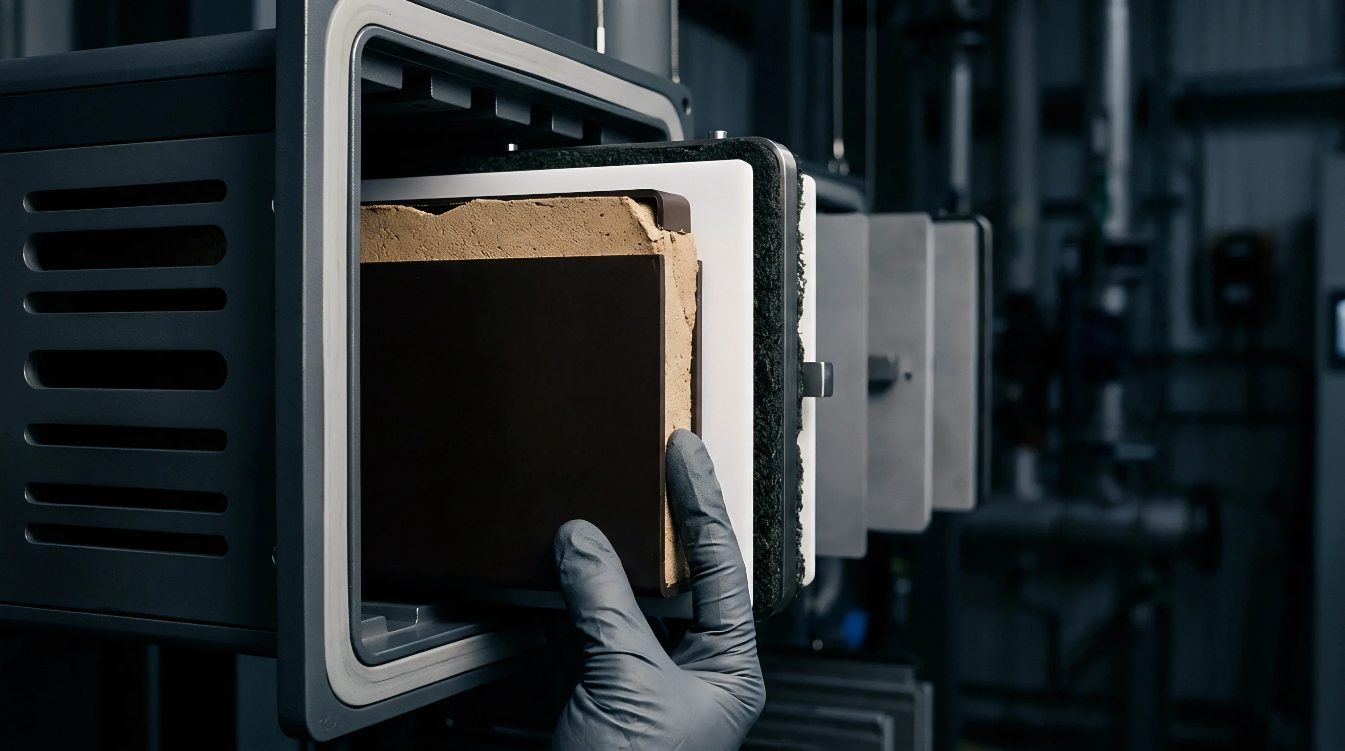
Unconstrained Volumetric Strain Mechanics
Anode-free lithium metal negative electrodes expand by roughly 0.5 micrometers for every milliampere-hour of deposited areal capacity. Silicon alloy composite anodes experience up to 300 percent volumetric strain at full lithiation, inducing extreme mechanical stress against solid electrolyte separators. When stack pressure falls below critical thresholds, microscopic voids form at the solid electrolyte interface during stripping steps.
These voids decrease active contact area, concentrate local current density, and accelerate dendrite penetration through grain boundaries in sulfide or oxide ceramic layers. The interface yields.
Ceramic oxide separators, such as lithium lanthanum zirconium oxide, possess young’s moduli exceeding 150 gigapascals and refuse to yield plastically at room temperature. Sulfide solid electrolytes, such as lithium phosphorus sulfur chloride glass-ceramics, exhibit lower young’s moduli around 20 gigapascals, allowing minor mechanical deformation to heal interfacial voiding under elevated pressure. Halide electrolytes present intermediate rigidity.
Applying external force drives soft lithium metal into conformal contact with the rigid separator, suppressing localized void nucleation and stabilizing interfacial impedance.
| Electrolyte Class | Young Modulus (GPa) | Min Stack Pressure (MPa) | Max Allowable Pressure (MPa) | Primary Low Pressure Defect |
|---|---|---|---|---|
| Sulfide (Li6PS5Cl) | 18 – 25 | 1.0 | 8.0 | Interfacial Voiding |
| Oxide (LLZO) | 140 – 170 | 5.0 | 15.0 | Dendrite Growth in Grain Boundaries |
| Halide (Li3YCl6) | 10 – 15 | 2.0 | 10.0 | Contact Resistance Surge |
| Polymer (PEO Complex) | 0.001 – 0.1 | 0.1 | 1.5 | Internal Short Circuit via Creep |
| Silicon Anode Sulfide | 20 – 30 | 3.0 | 12.0 | Particle Pulverization and Delamination |

Stack Pressure Window Selection
Operating pressure boundaries vary by orders of magnitude across ceramic, sulfide, halide, and polymer ionic conductors. Specifying lower compressive stress reduces structural pack weight but risks exponential capacity fade caused by high interfacial resistance. Excessive compressive stress forces metallic lithium through porous separator defects or crushes delicate composite cathode structures, shorting the cell.
High compressive loads also accelerate creep rate in metal housing materials, reducing long-term spring preload.
Sulfide systems function reliably within a 1.0 to 5.0 megapascal operating window at ambient temperature. Oxide systems demand pressures between 5.0 and 15.0 megapascals to maintain physical contact across unyielding ceramic planar surfaces. Polymer systems operate at lower loads near 0.2 to 1.0 megapascal, provided thermal management maintains temperature above polymer glass transition thresholds.
Balancing these electro-chemo-mechanical requirements dictates the selection of enclosure springs, end-plate rigidity, and housing materials.
Cell vendors frequently state that low contact pressure yields acceptable bench life, omitting the mechanical fixture specifications used to generate their published lifecycle charts.
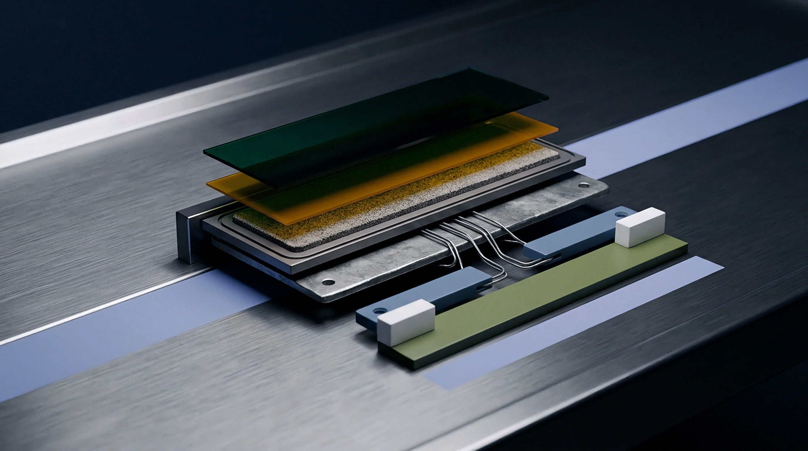

Clamp
Maintaining controlled force across cell faces requires custom spring geometry and rigid end-plates. Solid-state cell fixtures rely on passive mechanical springs, active pneumatic systems, or compliant microcellular foams to absorb dynamic stack growth while maintaining target contact stress. Selecting structural components involves balancing spring rate stability against enclosure volume constraints.

Compliant Element Dynamics
Polyurethanes and microcellular silicone foams exhibit time-dependent deformation under constant loading. Compression set reduces restoring force over hundreds of thermal and charge loops. When compliant foam pads take a permanent set, stack pressure falls below minimum threshold values, triggering interfacial voiding.
Wave springs and Belleville disc spring washers provide linear force delivery over greater deflection distances, presenting lower stress relaxation over extended calendar life.
Disc spring stacks arranged in series-parallel configurations compensate for height growth during charge while absorbing manufacturing tolerance stack-ups. Steel springs add dead mass to battery modules, lowering gravimetric energy density at the pack level. Titanium alloys offer lower weight and high yield strength, though raw material cost limits their application to specialized designs.
Engineering high-density compliance into tight module dimensions drives frame geometry choices.
Maintaining stack compressive stress within plus or minus 15 percent across an operating span from minus 30 degrees Celsius to 60 degrees Celsius prevents thermal expansion force spikes from cracking sulfide electrolyte layers.
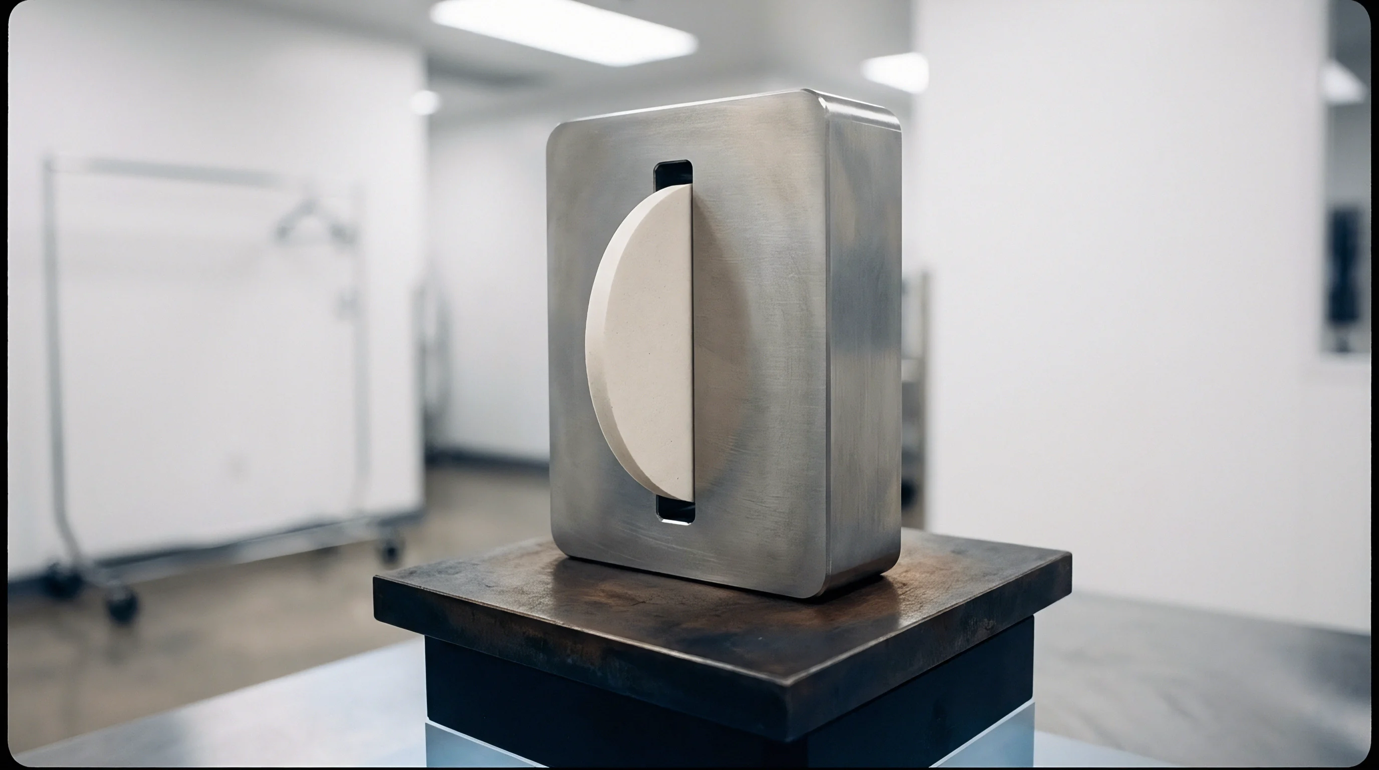
Load Frame Rigidity
Deflection in structural end-plates introduces pressure gradients across the cell active footprint. Flexible end-plates bow outward at the center under internal stack load, producing high compression along cell edges and insufficient compression at the center. Unbalanced pressure distributions cause uneven current density, localized lithium plating, and premature capacity degradation.
Structural end-plates utilize high-modulus aluminum alloys or carbon-fiber composite structures designed to limit center deflection to less than 0.05 millimeters under maximum stack swelling load. Tie rods threaded through perimeter plates secure the assembly, maintaining calibrated tension across the stack height. Torque accuracy during tie rod tightening dictates baseline mechanical equilibrium.
- Plate Bending Stiffness dictates the maximum thickness variance across active pouch surfaces during full lithium plating states.
- Spring Rate Linearity ensures steady compressive stress across the entire volumetric strain curve from zero to 100 percent state of charge.
- Thermal Expansion Matching prevents differential expansion between aluminum load frames and steel tie rods from dropping preload at sub-zero temperatures.
- Stress Relaxation Coefficient limits creep-induced force loss over a ten-year operational lifecycle under continuous load.
- Assembly Torque Tolerance controls baseline fixture force balance across multi-cell module stacks on production lines.
A resilient stack design uses low spring-rate elastomeric arrays coupled with high-rigidity load distribution plates to decouple structural frame bending from internal electrochemical breathing.


Gauge
Sensor integration within active cell stacks presents demanding spatial and thermal constraints. Validating stack stress profiles during engineering design cycles relies on thin-film sensor technologies capable of operating inside tight cell enclosures without introducing artificial stress concentration points.

Tactile Sensing Calibration
Piezo-resistive pressure mapping sheets map spatial contact variations down to fractions of a millimeter. Matrix sensing films placed between adjacent cell surfaces capture real-time stress redistribution during cycling. Polymer backing sheets must remain thin, typically under 0.2 millimeters, to avoid altering mechanical stack dynamics.
Local contact fails.
Calibration matrices adjust raw resistance readings for temperature sensitivity, transducer hysteresis, and loading rate. Piezoresistive arrays experience signal creep under constant static compression over extended test durations. Piezoresistive load cells positioned outside structural end-plates provide absolute force measurement, validating matrix sheet accuracy across long cycle runs.
| Sensor Technology | Thickness (mm) | Temp Range (°C) | Drift Rate (%/1000h) | Spatial Resolution |
|---|---|---|---|---|
| Matrix Piezoresistive Film | 0.10 – 0.20 | -20 to 70 | 3.5 to 6.0 | 1.0 mm x 1.0 mm grid |
| Capacitive Array Sheet | 0.15 – 0.30 | -40 to 85 | 1.0 to 2.5 | 2.0 mm x 2.0 mm grid |
| Button Strain Load Cell | 3.00 – 10.00 | -40 to 125 | 0.1 to 0.5 | Single point integral force |
| Fiber Bragg Grating Strain | 0.125 (fiber dia) | -50 to 150 | 0.2 to 0.8 | Continuous along optical fiber |

Sensor Drift and Thermal Compensation
Continuous compression at 60 degrees Celsius induces signal decay in polymer-based strain elements. Thermal expansion of test fixtures introduces fictitious force readings if compensation algorithms are absent. Thermocouples embedded adjacent to force sensors feed calibration models, isolating thermal frame expansion from electrochemical swelling force.
Calculating stress distributions across a 300 mm by 100 mm solid-state cell face requires evaluating localized pressure variations under dynamic charge states. Assume a baseline target average pressure of 2.00 megapascals applied across the 0.03 square meter active area, generating a total baseline force of 60.0 kilonewtons. During full charge expansion, internal electrochemical breathing increases total force to 90.0 kilonewtons, yielding an average stress of 3.00 megapascals.
Tactile sensor arrays map a central high-pressure zone covering 0.005 square meters where local force reaches 22.5 kilonewtons, resulting in a peak localized stress of 4.50 megapascals. Simultaneously, perimeter regions covering 0.005 square meters show a reduced force of 7.5 kilonewtons, corresponding to 1.50 megapascals local stress. This 3.00 megapascal stress gradient across the cell face exceeds the target distribution variance of plus or minus 15 percent, signaling structural end-plate deflection that demands stiffening rib modification.
Section 6.3 of IEC 62660-3 dictates that spatial force distribution variations across cell surfaces must not exceed 20 percent of nominal stack pressure during environmental thermal shock qualification.
Ignoring pressure mapping variations during initial bench setup leads to localized separator damage, undetected edge lithium plating, and sudden cell failure during hot temperature cycle qualification.


Cycle
Dynamic load tracking during continuous galvano-charge testing reveals non-linear mechanical responses. Stack stress varies dynamically as a function of state of charge, current rate, temperature, and accumulated cycle counts. Evaluating these dynamic mechanical responses requires rigorous testing matrix design.

Breathing Hysteresis Profiling
Lithium deposition produces different mechanical force curves during charge compared to discharge. During high C-rate charging, lithium atoms deposit faster than structural diffusion relaxes internal stress, raising transient stack pressure. During discharge, lithium stripping creates sub-surface voids before mechanical compressive forces re-consolidate the lithium layer, inducing force hysteresis.
Sub-zero operation slows mechanical creep rate in metal lithium and increases electrolyte interfacial shear modulus. Cold charging causes severe internal stress buildup at reduced states of charge, multiplying structural frame load. Low ambient temperatures exacerbate mechanical strain gradients within ceramic electrolyte layers.
Sensing film degrades.
What Stress Threshold Triggers Electrolyte Fracture?
Brittle ceramic separators yield when localized contact forces exceed their critical fracture toughness. Microcracks induced by mechanical stress concentration points allow metallic lithium dendrites to propagate directly through the solid electrolyte membrane. Sulfide glass-ceramics suffer plastic shear failure along primary sliding planes when exposed to combined shear and compressive stress fields.
- Interfacial Delamination occurs when low compression fails to collapse stripping voids during discharge, causing rapid contact resistance spikes.
- Separator Shear Failure occurs when non-uniform pressure gradients generate localized shear stress exceeding ceramic yield limits.
- Creep-Induced Shorting occurs when high localized compressive load forces soft metallic lithium through porous separator defects.
- Cathode Particle Fracture occurs when excessive stack pressure crushes high-nickel active material particles during volumetric expansion.
- Frame Fastener Relaxation occurs when cyclic mechanical breathing fatigue degrades tie rod preload over long operation loops.
Establishing stack pressure profile parameters requires a structured, step-by-step channel setup sequence across environmental test chambers.
- Mount cell inside calibrated rigid test fixture equipped with inline load cell and piezoresistive mapping sheet.
- Torque load frame fasteners in alternating pattern until baseline minimum contact pressure reaches target specification at ambient temperature.
- Place fixture assembly into thermal chamber and stabilize thermal equilibrium at 25 degrees Celsius for four hours.
- Perform three baseline formation charge and discharge loops at C/10 rate while recording dynamic force variations and voltage response.
- Elevate thermal chamber temperature to maximum operating limit of 60 degrees Celsius and verify continuous force drift remains within calibrated bounds.
- Execute fast charge cycle profile at 1C rate to capture peak dynamic pressure surge induced by mass transport lag.
- Reduce thermal chamber temperature to sub-zero threshold of minus 20 degrees Celsius and evaluate minimum relaxation force at zero state of charge.
- Extract pressure matrix spatial maps to verify contact stress distribution remains within target variance boundaries.
Interfacial contact resistance increases exponentially when stack compressive stress drops below electrolyte plastic yield limits during discharge loops.
How do subtle differences in mechanical fixture thermal mass skew high-rate thermal run-away propagation behavior inside multi-cell solid-state modules?


Margin
Dimensional variations across manufacturing batches require mechanical stack-up analysis. Cell pouch thickness tolerances, spring rate production spreads, foam pad density variations, and frame machining tolerances combine to alter nominal stack pressure in high-volume production builds.

End of Life Expansion Allowance
Irreversible lithium entrapment and side-reaction accretion accumulate over hundreds of deep discharge loops. Dead lithium formation increases baseline stack height independently of transient state-of-charge breathing. Enclosure spring geometry must retain sufficient deflection capacity to accommodate end-of-life thickness expansion without crushing cathode structures or over-stressing housing bolts.
Active compression systems, such as internal hydraulic diaphragms or variable pneumatic bladders, adjust volume dynamically to maintain constant stack pressure throughout calendar life. Mechanical spring packs rely on passive compliance, trading force stability for simplicity and lower manufacturing cost. Evaluating these structural approaches dictates pack integration strategy.
| Compression System | Tooling NRE ($) | Unit Cost Impact ($) | Mass Penalty (%) | Pressure Drift Control |
|---|---|---|---|---|
| Polyurethane Foam Pads | 15,000 | 12 – 25 | 2 – 4 | Poor (Creep Prone) |
| Belleville Spring Pack | 45,000 | 35 – 75 | 8 – 12 | Moderate (Linear Decay) |
| Wave Spring Frame Assembly | 60,000 | 50 – 110 | 6 – 10 | Good (Stable Preload) |
| Pneumatic Diaphragm Array | 220,000 | 180 – 350 | 14 – 20 | Excellent (Active Control) |
| Shape Memory Alloy Rig | 150,000 | 120 – 240 | 5 – 8 | Moderate (Temperature Dependent) |

Enclosure Tooling Tolerance Integration
Extruded aluminum casing walls flex under internal stack compression. Structural pack enclosures designed without accounting for wall deflection lose preload force when internal pressure pushes casing side-walls outward. Module designers must integrate structural tie-bars or cast exterior reinforcement ribs to maintain enclosure dimensional stability under maximum swelling loads.
Tolerance stack-up modeling utilizes worst-case monte carlo simulations across cell layer counts. In a 24-cell pouch module, a plus or minus 0.05 millimeter cell thickness manufacturing tolerance generates a plus or minus 1.2 millimeter variance in total uncompressed stack height. Spring selection must absorb this initial height variance without pushing baseline assembly pressure beyond qualification upper limits.
Extruded pack wall deflection under peak swelling loads alters internal spring displacement, dropping effective contact stress across central cell regions.
Standard purchase contract clause 8.4 assigns financial liability for casing structural yield directly to the pack assembler when module pre-load specifications omit end-of-life growth force allowances.

Warranty
Commercial agreements specify performance parameters alongside rigid environmental operating envelopes. Solid-state cell performance guarantees depend directly on preserving specified stack pressure windows throughout the field operating life. Splitting mechanical containment responsibilities across commercial supply chain boundaries requires unambiguous technical documentation.

Interfacial Compliance Seams
Risk allocation splits cleanly where the cell supplier passes structural integration to the pack builder. Cell manufacturers provide capacity, impedance, and cycle-life performance curves contingent on the pack structure maintaining strict compressive force limits. If pack-level spring elements suffer thermal degradation or structural end-plates deform beyond specification limits, cell warranties terminate immediately.
Defining warranty terms demands integration of pressure measurement logs into field battery management systems. Smart end-plate strain sensors or thin digital load cells track mechanical force history alongside electrical and thermal metrics. BMS firmware records pressure excursions outside approved qualification windows, generating diagnostic flags that isolate mechanical pack failures from cell electrochemistry defects.

Dossier Requirements for Qualification Sign Off
Final acceptance documentation demands complete pressure mapping arrays across temperature ranges. NPI engineering dossiers must include verified structural deflection finite element models, spring stress relaxation laboratory data, dynamic pressure breathing maps, and life-cycle pressure decay projections. Omitting dynamic pressure validation data exposes projects to catastrophic field recalls when spring stress relaxation drops stack compression below critical interfacial thresholds.
Tooling sign-off criteria mandate first-article inspection of structural frames under full load conditions. Production line end-of-line testing incorporates load-deflection verification checks on every completed module frame assembly. Documenting precise pre-load baseline force values for every serialized module establishes traceable quality data, locking down supplier responsibility boundaries before pack shipments leave the factory door.