Standardized Methods for Measuring Battery Module Stack Pressure
Standardized battery module stack pressure measurement relies on calibrated tactile sensors and rigid, temperature-compensated test fixtures.
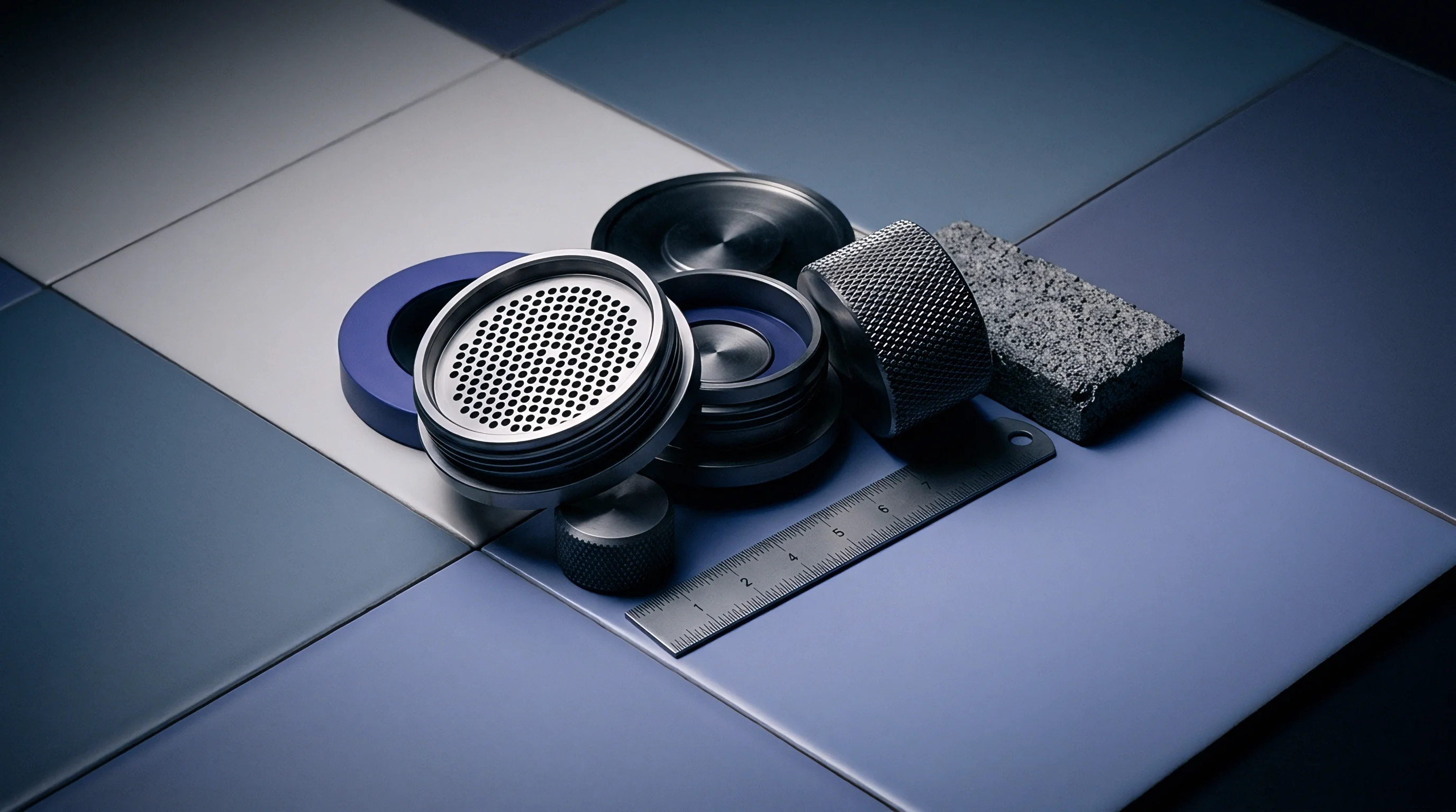

Gauge
Pouch and prismatic cells require controlled mechanical confinement to prevent delamination and maintain internal ionic pathways throughout their operational lifecycle. Solid-state load cells, capacitive tactile sheets, piezoresistive array matrices, and optical fiber Bragg gratings represent the primary hardware instruments used to quantify internal clamping forces. Selecting a sensing architecture requires balancing thickness, temperature drift, spatial resolution, and dynamic response speed within the compressed stack.
Tactile piezoresistive arrays have thin profiles, typically between 0.10 mm and 0.20 mm, allowing insertion between adjacent cells without substantially altering the mechanical stack-up geometry. Inserting any sensor modifies local stiffness, however; a 0.20 mm layer added to a tight pouch stack introduces localized thickness that concentrates force along the sensor boundary, creating spatial measurement artifacts up to 12% above actual surface stress. Because piezoresistive inks are thermally sensitive, uncompensated film sensors experience zero-point drift exceeding 15% of full-scale reading when module temperatures rise from 25°C to 55°C during rapid discharge testing.
Strain-gauge button load cells deliver superior measurement repeatability and thermal stability across extended cycle testing. They do require structural pocket integration inside module endplates or intermediate compression plates. This reliance on discrete button load cells limits spatial pressure mapping to single-point values, missing localized pressure peaks caused by anode thickness variations near tab connections.
| Sensor Technology | Thickness (mm) | Spatial Resolution | Temperature Drift (% FS/°C) | Sampling Rate (Hz) |
|---|---|---|---|---|
| Piezoresistive Tactile Array | 0.10 – 0.20 | 25 – 100 sensing points/cm² | 0.35 – 0.50 | 100 – 500 |
| Capacitive Matrix Sheet | 0.35 – 0.70 | 4 – 16 sensing points/cm² | 0.08 – 0.15 | 20 – 50 |
| Strain Gauge Button Cell | 3.00 – 12.00 | Single point per sensor | 0.01 – 0.03 | 1000 – 5000 |
| Fiber Bragg Grating (FBG) | 0.12 – 0.25 | Discrete point array along fiber | 0.02 – 0.05 | 2000 – 10000 |
Capacitive tactile matrices offer lower thermal sensitivity than piezoresistive alternatives, holding stable baseline measurements across broad temperature sweeps. They do require thicker dielectric substrate layers, typically 0.35 mm to 0.70 mm. Installing capacitive sheets into tight module cavities compresses adjacent elastic foam pads beyond their nominal design point, altering the initial mechanical boundary condition.
- Creep Deformation Drift occurs when continuous mechanical loading degrades piezoresistive sensor substrate layers over multi-month cycling trials, causing signal attenuation.
- Thermal Zero Shift arises from differential thermal expansion between active sensor element materials and high-density copper or aluminum current collectors.
- Edge Shear Interference occurs when cell edge rounding shear forces deform sensor perimeter traces, generating false high-pressure readings along cell borders.
- Hysteresis Signal Lag develops during fast charge and discharge transitions, preventing sensor response from tracking physical cell relaxation curves accurately.
Fiber Bragg grating sensors use optical fibers embedded inside intermediate silicone or polyurethane damping pads. Optical wavelength shifts track strain independent of electromagnetic interference generated by high-current electrical switching. Fiber Bragg grating systems demand complex optical interrogator instrumentation, raising fixture tooling costs significantly during early pilot validation phases.
Piezoresistive tactile array sensors uncompensated for thermal drift introduce pressure measurement errors up to 18% when cell surface temperatures exceed 50°C during continuous 2C discharge cycles.
Sensors must calibrate against rigid reference plates inside environmental chambers across the full intended thermal operating envelope before collecting module data. Calibration procedures that rely solely on ambient temperature bench presses yield invalid surface pressure calculations once module thermal management systems activate. Uncompensated film arrays cannot provide accurate stack pressure profiles across dynamic thermal cycles without thermal zero-drift correction factors to separate physical cell expansion from resistance shifts caused by temperature.

Breathing
Lithium-ion cells exhibit volume changes during routine charge and discharge cycles. Lithium ions intercalate into the graphite structure of the anode during charging, driving lattice expansion that translates into macroscopic cell thickness increases. Reversible lithium intercalation generates cyclic mechanical force variations against module endplates, known as dynamic breathing.
Lithium nickel manganese cobalt oxide chemistry paired with pure graphite anodes displays reversible thickness variations between 1.5% and 3.0% at full state of charge. Silicon-graphite composite anodes expand significantly further, demonstrating volume increases between 8% and 18% depending on silicon mass fraction and particle geometry.
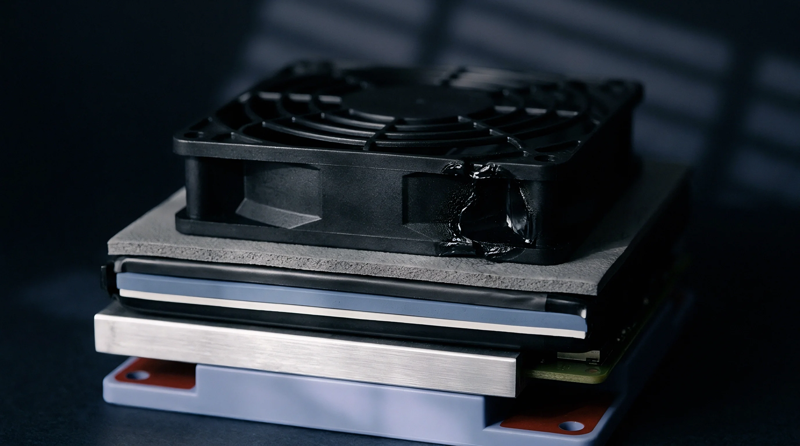
How Frequently Does Cyclic Expansion Alter Cell Interface Mechanics?
Reversible expansion occurs on every charge-discharge cycle, but irreversible volumetric expansion accumulates across thousands of cycles due to solid electrolyte interphase growth, active material isolation, and internal gas formation. Total stack force within a rigid, fixed-volume module frame increases continuously over operational life.
Uncontrolled stack pressure growth accelerates capacity degradation. Internal pressures exceeding 1.2 MPa compress microporous polyolefin separators, reducing pore volume and restricting liquid electrolyte ionic conductivity. Separator pore compression elevates internal electrical impedance, generating localized current hot spots that accelerate lithium plating during fast-charging operations.
Maintain stack pressure within cell manufacturer specification windows to prevent separator pore closure and micro-delamination along active material coatings.
Pouch cell formats expand primarily along their planar thickness axis, maintaining stable width and height dimensions due to perimeter pouch seal constraints. Prismatic cells encased in rigid aluminum cans exhibit non-uniform face bulging. The center of a prismatic cell face deflects outward significantly more than the reinforced corners, creating localized pressure concentration zones that can restrict cooling fluid channels across adjacent plates.
Pressure distribution changes non-linearly as state of health declines. Early in lifecycle, pressure distribution across cell faces remains uniform. As gas pockets form and localized solid electrolyte interphase growth builds up near current collector tabs, peak pressure zones shift toward cell perimeters.
Standard single-point load cell fixtures miss these spatial variations entirely, reporting average stack force while localized areas exceed destructive stress thresholds.
Determining the precise transition point where reversible cyclic breathing transitions into permanent structural cell deformation requires continuous multi-axis strain tracking under variable mechanical boundary conditions.
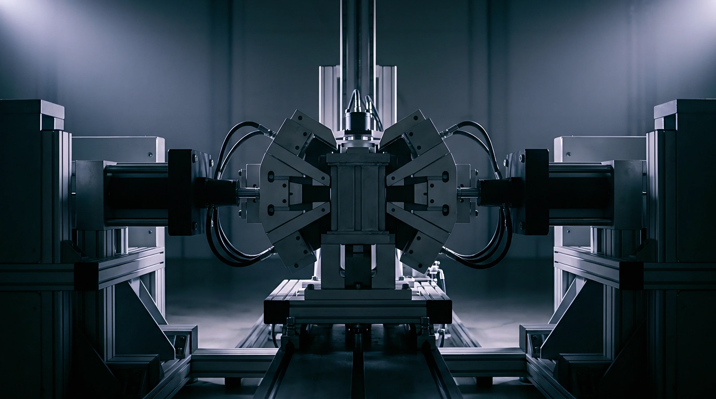
Fixturing
Standardized measurement methods require absolute control over mechanical boundary conditions during module testing. Test fixtures establish either constant-volume or constant-force constraints around the cell stack. A constant-volume fixture uses rigid steel endplates connected by low-expansion tie rods, holding overall stack length fixed while internal pressure fluctuates.
A constant-force fixture uses spring packs or hydraulic actuators to hold clamping force stable while allowing stack length to vary.
Rigid frames simulate structural pack enclosures where module space is tightly constrained by vehicle chassis members, whereas spring-loaded constant-force frames simulate flexible module enclosures designed with compliant compression pads.
Endplate bending deflection compromises measurement accuracy in constant-volume test frames. Under a 40 kN total stack expansion force, a 15 mm thick aluminum endplate flexes outward at its center by up to 0.45 mm. Endplate flexure converts uniform cell compression into perimeter-weighted loading, artificially lowering measured center-point pressure while overstressing cell edges.
Test frame endplates must maintain a maximum deflection limit under 0.05 mm across the maximum expected stack force range.
- Mount the bare test frame onto a three-axis coordinate measuring machine to map baseline structural flatness.
- Install precision ground steel gauge blocks matching exact module stack dimensions into the fixture cavity.
- Torque tie-rod fasteners in a cross-pattern sequence to 50% target preload value using a calibrated torque wrench.
- Apply full target preload torque, recording strain gauge response across all tie rods to verify load symmetry.
- Heat the assembled fixture to 60°C inside an environmental chamber and maintain thermal soak for four hours.
- Re-measure fixture cavity dimensions to verify that thermal expansion mismatch between steel rods and aluminum plates does not exceed allowable tolerance limits.
Compliant compression pads placed between adjacent cells modulate stack stress build-up. Microcellular polyurethane foams, silicone foams, and aerogel blankets serve as intermediate cushioning materials. Pad spring rate defines the mechanical load path.
A high-stiffness pad transfers cell expansion forces directly into the module frame, driving pressure up rapidly. A low-stiffness pad absorbs cell volume growth through internal foam cell collapse, keeping stack pressure stable over operational life.
Polyurethane foam pads suffer stress relaxation under long-term compressive loading. When held at 30% strain for 1,000 hours at 40°C, microcellular polyurethane loses up to 22% of its original pushing force. Silicone foams demonstrate superior resistance to stress relaxation, losing under 8% compressive force under identical conditions.
ISO 12405-4 specifies mechanical test enclosure rigidity requirements, mandating that frame compliance contribute less than 2% to measured total stack dimensional variance under peak load.
Thermal expansion mismatch between fixture components alters initial preload values. Steel tie-rods paired with aluminum endplates relax total clamping force during sub-zero thermal storage testing because aluminum contracts faster than steel. Failure to calculate frame thermal compliance leads to invalid low-temperature stack pressure measurements that do not reflect actual pack mechanical conditions.
Selecting incorrect fixture compliance parameters masks cell degradation mechanisms during qualification testing, leading to pack structural failure when production cells expand against rigid vehicle enclosures.

Procedure
Validating stack pressure requires standardized test procedures executed under controlled environmental and electrical conditions. ISO 12405-4 and IEC 62660-3 establish standard methodologies for testing lithium-ion battery modules, but require supplementation to define stack pressure measurement protocols explicitly. Procedures must define pre-conditioning steps, state-of-charge reference points, temperature stabilization holds, and data acquisition sampling frequencies.
Pre-conditioning establishes consistent mechanical baseline states across tested modules. Newly manufactured cells exhibit initial surface irregularities and transient pouch gas pockets that distort baseline pressure readings. A valid protocol applies three full charge-discharge cycles at ambient temperature prior to applying final fixture clamp torque.
Initial clamping force setting occurs precisely at 50% state of charge and 25°C ambient temperature after a four-hour thermal soak.
| Test Parameter | Static Baseline Protocol | Dynamic Drive Protocol | Fast-Charge Aging Protocol |
|---|---|---|---|
| Ambient Temperature (°C) | 25 ± 2 | -20 to +55 variable | 45 ± 2 |
| State of Charge Range (%) | 0 to 100 step-wise | 10 to 90 continuous cycle | 0 to 80 high rate |
| Thermal Soak Duration (h) | 4 minimum | 2 at each step | 1 between cycles |
| Pressure Data Sampling (Hz) | 0.1 | 10.0 | 1.0 |
| Electrical C-Rate | C/3 calibration rate | Dynamic peak 3C pulses | 2C continuous to 4C pulse |
Sampling frequency selection directly impacts data integrity. Static degradation monitoring requires low sampling rates around 0.1 Hz, minimizing data storage requirements over multi-month cycle life studies. Transient response mapping during high-power drive cycles or fast-charging pulses requires data collection at 10 Hz or higher.
Rapid thermal expansion of active material during 4C fast-charging pulses generates brief pressure spikes that lower-frequency data loggers miss entirely, obscuring transient loads that degrade separators.
- Thermal Stabilization Soak holds the module at specified test temperature for a minimum of four hours to eliminate internal thermal gradients before recording force metrics.
- Step-Wise State-of-Charge Sweep records force at 10% SOC intervals with 30-minute rest periods at each step to isolate open-circuit relaxation from dynamic stress.
- Tare Weight Zeroing resets pressure transducer baselines prior to final mechanical constraint torquing to account for physical sensor dead weight.
- Multi-Axis Realignment Inspection verifies structural squareness of compression endplates using dial indicators before starting electrical cycling sequences.
Benchtop measurements recorded without standardized thermal stabilization cycles produce unrepeatable pressure profiles. A module measured immediately after high-current discharge exhibits elevated core cell temperatures while surface temperature sensors report ambient conditions. Internal thermal expansion elevates physical stack force beyond true equilibrium values.
Standard testing methods mandate recording stack force continuously across three consecutive charge-discharge cycles to prove baseline mechanical repeatability before initiating long-term aging routines.
Contractual agreements between pack integrators and testing laboratories frequently incorporate UN 38.3 transport testing standards as mechanical baselines. UN 38.3 vibration and shock protocols evaluate structural containment integrity rather than internal cell pressure dynamics, requiring custom contract addenda to define explicit stack stress limits during transport simulation.
According to standard supply agreement terms for EV battery modules, any pressure measurement dataset collected without documented four-hour thermal soak holds prior to initial torque application is invalid for warranty claim adjudication.

Derivation
Calculating expected stack pressure requires converting overall module clamping force and frame deformation into planar surface stress distributions. Consider a 12-cell prismatic module stack with microcellular polyurethane foam pads placed between every adjacent cell pair. Each cell features planar contact face dimensions of 220 mm width by 100 mm height, yielding an active contact surface area of 0.022 m² (220 cm²).
Target initial stack stress is specified at 0.35 MPa (350 kPa) at 50% state of charge and 25°C ambient temperature. Calculating total required initial clamping force Finitial involves multiplying surface area by target pressure:
Finitial = 0.022 m2 × 350,000 N/m2 = 7,700 N (7.7 kN)
Module tie rods are torqued to apply this 7.7 kN force across the endplates. As cells age over 1,500 cycles, cumulative irreversible thickness expansion adds 0.80 mm per cell face. For a 12-cell stack, total unconstrained expansion length Δ Lraw equals 9.60 mm.
The foam pads and structural tie-rods absorb this expansion, developing an elevated end-of-life pressure state.
| Tolerance Condition | Pad Stiffness (N/mm/cm²) | Frame Deflection (mm) | EOL Stack Force (kN) | EOL Stack Stress (MPa) |
|---|---|---|---|---|
| Nominal Design Base | 1.25 | 0.30 | 38.5 | 1.75 |
| High-Stiffness Extreme | 2.10 | 0.12 | 58.2 | 2.65 |
| Low-Stiffness Compliant | 0.65 | 0.48 | 22.4 | 1.02 |
Assuming a nominal microcellular polyurethane foam spring rate of 1.25 N/mm per square centimeter of surface area, the total pad stiffness Kpad for a 220 cm² face equals 275 N/mm per pad interface. Twelve pads configured mechanically in series yield an equivalent stack foam spring rate Kstackpad calculated by dividing individual pad stiffness by pad count:
Kstackpad = frac275 N/mm12 = 22.92 N/mm
Module frame tie-rods possess structural stiffness. Four steel tie-rods with cross-sectional areas of 28 mm² each and lengths of 350 mm exhibit total axial tensile stiffness Krods calculated using Young’s modulus for steel (210 GPa):
Krods = frac4 × 28 mm2 × 210,000 N/mm2350 mm = 67,200 N/mm
Because the foam pads and tie-rods act as parallel load paths within the constrained module frame, the system stiffness is governed primarily by the highly compliant foam component. Total end-of-life force addition Δ FEOL is calculated by multiplying unconstrained expansion length by the combined system stiffness:
Δ FEOL = 9.60 mm × 22.92 N/mm = 220 N per pad interface → 30.8 kN total
Adding initial pre-charge force of 7.7 kN to the operational expansion load yields a total end-of-life clamping force of 38.5 kN. Dividing 38.5 kN by the 0.022 m² cell surface area results in an end-of-life nominal stack stress of 1.75 MPa. Endplate structural bending causes non-uniform deflection, adding a 25% peak stress multiplier along cell perimeters, driving localized peak edge pressure to 2.19 MPa.

Contract
Establishing clear commercial and legal boundaries between cell manufacturers, module integrators, and pack assembly practices prevents disputes over degradation liabilities. Cell suppliers publish maximum allowable initial clamping pressures alongside absolute peak expansion pressure limits over cell lifecycle. Exceeding published pressure thresholds voids cell cycle-life guarantees and safety warranties entirely.
Integrators must prove compliance with cell mechanical specification limits by delivering audited standard testing documentation. The module integrator assumes full financial liability for cell degradation if pack frame stiffness exceeds specified limits, causing stack pressure to cross maximum warranty limits prematurely.
- Calibrated Sensor Traceability Records proving that instrumentation used for quality acceptance audits underwent chamber calibration within 30 days of testing.
- Continuous Thermal-Pressure Log Files demonstrating that pre-charge clamping force remained within target limits during all factory baseline setting operations.
- Endplate Deflection Certification Documents verifying that structural enclosure bending remains under maximum allowable millimeter limits under full test load.
- Batch Damping Pad Modulus Audits confirming that incoming lot shipments of elastic compression foam match specified spring rate curves within a 5% tolerance band.
Responsibility shifts at the physical module boundary. The cell manufacturer guarantees electrochemical performance provided the module structure maintains cell face pressure between 0.20 MPa and 1.50 MPa across all operational temperatures and states of charge. If pressure drops below 0.20 MPa, delamination risk increases; if pressure rises above 1.50 MPa, separator compression accelerates capacity loss.
Properly constructed procurement documentation binds cell warranty enforcement directly to verified, standardized pressure data recorded during incoming batch acceptance inspections.
A simple rule of thumb holds that whenever measured end-of-life pressure exceeds twice the initial factory pre-load, the pad compliance selection is insufficient for the expansion characteristics of the chosen cell chemistry.