Prismatic Lithium Cell Mechanical Preload Selection and Swelling Management
Prismatic cell lifetime depends on balancing initial mechanical preload pressure between 0.2 and 0.4 MPa to suppress lithium plating while accommodating end-of-life swell within structural limits.


Expansion
A fresh 280 Ah lithium iron phosphate cell in a rigid aluminum enclosure measures 71 mm in thickness along its shortest dimension when resting at thirty percent state of charge. During the initial full charge to 3.65 V at a 0.5C rate, the same enclosure broadens across its broad faces by 0.35 mm under zero external restraint. Force rises sharply.
This dimensional shift stems directly from the intercalation of lithium ions into the graphite matrix at the negative electrode, where the unit cell volume expands by approximately ten percent along the c-axis during complete lithiation. When multiple cells sit side-by-side inside an automotive or stationary battery module, unmanaged dimensional shifts distort the enclosure geometry, destroy thermal interface contact, and induce premature structural failure of inter-cell busbars.

Lattice Strains and Macro Wall Deflection
Microscopic atomic displacement scales directly into macroscopic casing strain through the sum of all internal layer changes. The stacked architecture of modern prismatic formats concentrates dimensional changes normal to the current collector planes. Graphite active material undergoes discrete phase transitions during charging, transitioning through staged structures from dilute Stage 1′ to fully lithiated Stage 1 LiC6.
These crystallographic structural shifts exert mechanical forces against the thin aluminum casing walls, which typically range between 0.6 mm and 1.0 mm in nominal wall thickness. Without exterior mechanical support, the center of the large planar face bows outward while the seam welds experience intense tensile stress concentrations.
Swelling alters geometry. The outer aluminum shell behaves as a thin membrane under internal pressure, bending disproportionately along its central axis. Casing deflections reduce the effective contact surface area between the cell face and adjacent liquid cooling plates, generating thermal gradients across the jellyroll.
Non-uniform temperatures induce localized current density hot spots, accelerating degraded capacity pathways along the cell perimeter. Unchecked face deflections exceeding 2.0 mm per cell frequently shear the laser welds on rigid busbars, breaking electrical circuit continuity across the module string.

Solid Electrolyte Interphase Accumulation Mechanics
Chemical side reactions permanently alter the physical footprint of the jellyroll over extended cycle life. The decomposition of organic carbonate solvents at the graphite surface consumes active lithium and produces an inorganic-organic composite film known as the solid electrolyte interphase layer. Continuous cracking and regeneration of this passive interface layer during thermal and mechanical cycling drives steady, irreversible volumetric growth of the negative electrode stack.
Gas generation accompanies interphase growth. Trace moisture contamination, electrolyte reduction, and cathode oxygen release under high SOC or elevated thermal conditions increase gas pressure within the hermetically sealed can. Swelling pressures generated by gas accumulation compound the mechanical forces exerted by solid phase growth.
Designers who neglect to account for both solid layer thickening and internal gas pressure accumulation face module housing rupture within the first thousand operational cycles.


Breathing
Volumetric change inside a prismatic cell consists of two distinct components that require separate design mitigation strategies. Reversible dimensional shifts occur continuously during every charge and discharge phase, driven purely by the transient insertion and extraction of lithium ions within host lattice structures. Cells breathe continuously.
Irreversible growth occurs progressively across thousands of operational hours as solid interphase products accumulate, active materials undergo isolation, and metallic lithium plates onto the graphite surface.

Reversible Lithiation Breathing versus Irreversible Growth
The magnitude of transient operational expansion tracks state of charge in a non-linear profile matching the open-circuit voltage plateaus of the active chemistry. Lithium iron phosphate formulations display a relatively flat breathing profile across forty to eighty percent SOC, followed by a steep increase near full charge. Nickel manganese cobalt oxide variants exhibit a more linear swelling slope across the entire SOC window due to continuous phase changes within the nickel-rich layered oxide cathode and graphite anode balance.
Transient breathing demands elastomeric compliance within the module structure to accommodate daily dimensional swings without exceeding peak force thresholds.
A standard 305 Ah LFP prismatic cell exhibits a reversible thickness variation of 0.8 mm between zero and one hundred percent state of charge under a constant 0.3 MPa restraint load.
Irreversible expansion represents permanent thickness gain that persists even when the cell undergoes complete discharge. Solid phase accretion, active material exfoliation, and electrode gapping contribute to a persistent growth rate ranging from 1.5 percent to over 8 percent of total original cell thickness by end of life. Managing this cumulative growth requires predicting the total displacement force at eighty percent remaining capacity and sizing inter-cell compliant pads accordingly.

Gas Generation Dynamics in Sealed Prismatic Cans
Volatile species generated through chemical degradation increase gas volume inside the free headroom above the electrode stack. Carbon monoxide, carbon dioxide, ethylene, and fluoro-organics accumulate progressively over long storage and high-temperature cycling periods. Internal pressure spikes.
Internal gas build-up presses the broad planar walls of the aluminum casing outward, transferring significant mechanical load onto adjacent module structural components.
- Gas pocket formation isolates active material areas, lowering usable capacity and raising local internal resistance.
- Casing bulge accumulation reduces thermal interface material thickness at high spots while creating air gaps at low spots.
- Vent disk stress accumulation lowers the rupture threshold of safety pressure relief valves under ambient operating vibrations.
- Separator compression bias squeezes liquid electrolyte out of high-pressure central zones toward outer cell margins.
Cell suppliers frequently attribute premature capacity loss or bulging to improper pack-level mechanical restraint rather than manufacturing defects or internal chemical degradation. Integrators without clear force transducer logs during qualification testing struggle to challenge these warranty denials.

Clamp
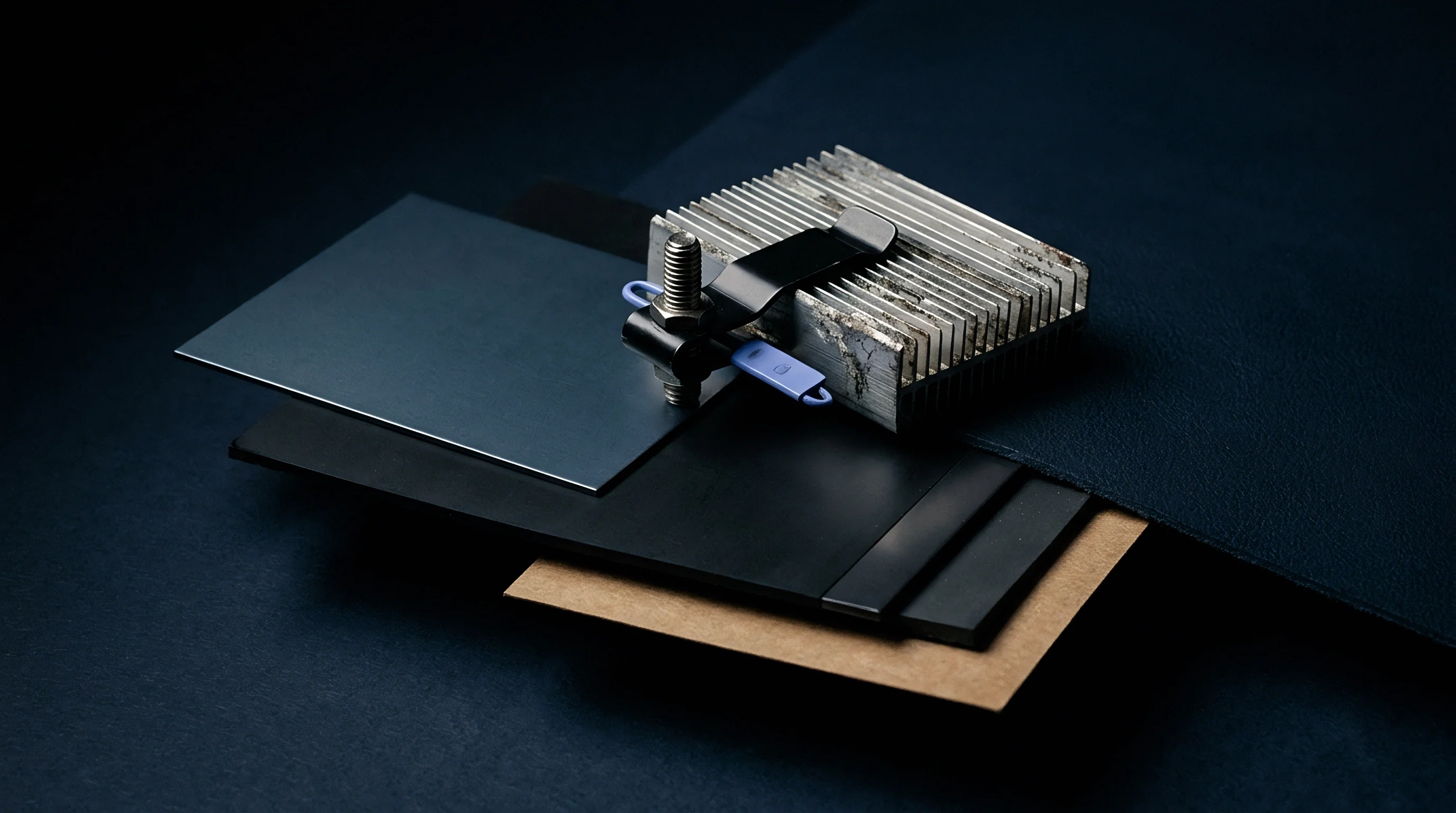
Applying an initial mechanical hold down load stabilizes the internal electrode architecture, maintains uniform particle-to-particle electrical contact, and prevents separator displacement. Preload controls plating. Setting the mechanical load too low allows separator motion, micro-delamination, and localized lithium metal deposition during low-temperature charging.
Setting the load too high crushes the porous separator, chokes electrolyte diffusion channels, and accelerates capacity degradation through localized dry-out.

How Does Compression Mitigate Lithium Plating?
Maintaining continuous uniform face pressure across the jellyroll suppresses the formation of metallic lithium dendrites during fast charging conditions. Dynamic mechanical restraint prevents local layer separation, ensuring that lithium ions migrate evenly into graphite host structures rather than nucleating as metallic deposits on the anode surface. Uniform force application lowers interfacial charge transfer impedance across the entire active surface area.
Contact resistance decreases. Sustained compression preserves microscopic contact pathways between conductive carbon additive networks and active material particles. When cell faces expand under load against an elastic restraint, the reaction pressure increases, maintaining intimate physical proximity between current collector foils, active coatings, and polyolefin separators throughout the operating lifetime.
| Chemistry Type | Nominal Capacity (Ah) | Initial Preload (MPa) | Max EOL Preload (MPa) | Reversible Swell (%) | Irreversible Swell (%) |
|---|---|---|---|---|---|
| LFP (LiFePO4) | 280 – 320 | 0.2 – 0.4 | 1.0 – 1.2 | 1.2 – 1.8 | 3.0 – 5.0 |
| NMC 811 | 180 – 240 | 0.3 – 0.5 | 1.2 – 1.5 | 2.0 – 2.5 | 5.5 – 8.0 |
| NMC 622 | 120 – 160 | 0.2 – 0.4 | 0.8 – 1.0 | 1.5 – 2.0 | 4.0 – 6.0 |
| Si-Graphite (5% Si) | 100 – 200 | 0.5 – 0.8 | 1.8 – 2.2 | 3.5 – 5.0 | 8.0 – 12.0 |

Elastomeric Cushion Selection and Compression Set
Inserting elastic compression pads between adjacent cells absorbs transient breathing while accommodating long-term thickness growth without exceeding safe pressure limits. Open-cell microcellular polyurethane and specialized silicone foams serve as the primary elastomeric buffers in high-density module designs. Elastomers creep slowly.
Selection of pad material depends heavily on resistance to long-term compression set under elevated temperatures.
Failure to maintain inter-cell compression pressure above 0.05 MPa across all operating temperatures invalidates supplier cycle life performance warranties under standard purchase agreements.
Engineers evaluate force-versus-displacement curves across temperature bands from minus forty to sixty degrees Celsius when specifying cushioning media. The compression pad must offer a low initial spring rate to yield during thermal expansion, yet retain sufficient elasticity over ten years to prevent complete loss of clamping pressure when the pack drops to low ambient temperatures.
- Microcellular polyurethane foam offers excellent energy absorption and non-linear spring dynamics but exhibits higher compression set above fifty degrees Celsius.
- High-consistency silicone foam maintains predictable elasticity across wide temperature ranges with minimal compression set over extended aging periods.
- Aerogel insulation composites combine low thermal conductivity for thermal runaway barrier prevention with high spring stiffness that requires careful force budget management.
- Cross-linked polyethylene foam provides low-cost cushioning for lower cycle life applications but suffers rapid stress relaxation under sustained static loads.
Optimal mechanical compression design balances initial assembly tension against end-of-life structural pressure limits without crushing inter-cell insulation layers.


Structure
Module frame hardware must contain the cumulative expansion forces generated by multiple cells aligned in series or parallel strings. End plates and tensioning tie rods form the primary load path for mechanical restraint. Deflection destroys modules.
Structural components designed without adequate bending stiffness flex outward under internal pressure, allowing central cells to swell excessively while edge cells experience extreme localized pinches.

End Plate Bending Rigidity and Module Deflection
End plate design relies on structural beam deflection mechanics to control maximum center-face displacement. Thicker monolithic aluminum end plates or ribs engineered with variable cross-sections reduce outer face bowing. When an end plate bows under cell expansion, the non-uniform displacement distribution causes unequal current density distribution inside the cells, accelerating degradation in the central regions of the electrode stack.
| Material Designation | Yield Strength (MPa) | Elastic Modulus (GPa) | Thermal Expansion (10^-6/K) | Relative Weight Index |
|---|---|---|---|---|
| Aluminum 6061-T6 | 276 | 68.9 | 23.6 | 1.00 |
| Stainless Steel 304 | 215 | 193.0 | 17.3 | 2.85 |
| High-Strength Steel S700MC | 700 | 210.0 | 12.0 | 2.75 |
| Glass Composite G10/FR4 | 270 | 24.0 | 10.0 | 0.65 |
| Magnesium Die-Cast AZ91D | 160 | 45.0 | 26.0 | 0.65 |
Selecting high elastic modulus materials minimizes component thickness while maintaining strict outer boundary geometry. Advanced enclosure designs incorporate high-strength structural steel or carbon composite end plates to limit total structural deflection below 0.5 mm at peak end-of-life expansion loads.
Structural module end plates must be engineered to resist maximum swelling forces without exceeding material yield thresholds under full operational shock loads.

Tie Rod and Side Strap Tensioning
Tension elements wrap around the cell string to connect the opposing end plates, forming a continuous load containment loop. Stainless steel side straps, woven aramid bands, and threaded steel tie rods serve as common tensioning components. Fasteners lose tension.
Thermal expansion mismatch between aluminum cell cans, steel tie rods, and plastic insulating trays alters mechanical tension across temperature swings.
- Preload tension torque tolerances specified on production assembly drawings must account for immediate elastic relaxation of inter-cell foam pads during initial clamping.
- Laser welding parameters for side straps require continuous load monitoring during energy delivery to guarantee consistent static holding force after weld pool solidification.
- Threaded tie-rod assemblies demand thread-locking compounds rated for continuous operating temperatures up to eighty-five degrees Celsius to prevent vibrational backing-off.
- Corner insulator radius designs must prevent edge-cutting stresses on tension straps during high g-force dynamic impact events.
Per UN 38.3 regulatory testing frameworks, mechanical restraint systems must retain structural integrity without plastic deformation or strap loosening following standard transportation vibration sequences.


Validation
Quantifying expansion forces across operational lifetimes requires calibrated test channels capable of simultaneously recording force, displacement, temperature, and electrical parameters. Test channels apply controlled load boundaries to single cells or full modules under precise environmental control. Test fixtures operate in either constant-gap or constant-force control modes to simulate rigid battery module frames or compliant spring-restrained systems.

Dynamic Load Mapping and Force Transducer Testing
To accurately capture the non-linear force evolution of a prismatic cell over time, testing facilities deploy multi-axis load cells paired with optical strain tracking system instrumentation. Laser displacement sensors measure outer casing deflection down to micrometer resolution while piezoresistive load cells capture rapid force transients during aggressive high-rate charge and discharge pulses. Data gathered under variable C-rates reveals that transient expansion forces increase substantially during high-current charging due to sharp localized lithium concentration gradients near the separator face.
To establish a verified force-displacement profile for a new cell model, the testing facility executes a standardized characterization sequence on calibrated hydraulic or electromechanical bench fixtures.
- Mount the uncharged prismatic cell into the multi-axis test fixture between ground steel platen plates.
- Position calibrated strain-gauge load cells inline with the primary axis of expansion normal to the broad cell face.
- Apply the supplier-specified initial preload force using precision screw drives while monitoring real-time load distribution.
- Connect calibrated thermocouples to the top, center, and bottom regions of both broad cell faces.
- Enclose the test fixture within a climate-controlled chamber set to twenty-five degrees Celsius and allow thermal equilibration for four hours.
- Perform three baseline charge-discharge cycles at 0.33C rate while recording continuous force, voltage, current, and thickness displacement metrics.
- Step the ambient chamber temperature to minus ten, fifteen, forty-five, and sixty degrees Celsius, repeating charge-discharge profiles at each thermal step.
- Transition the control system to constant-gap mode and execute extended lifetime cycling to plot pressure accumulation versus throughput capacity loss.
Testing must record force curves across both constant-gap and constant-force boundary conditions to accurately model rigid module framing versus elastic spring retention dynamics.

Accelerated Mechanical Aging Test Sequences
Simulating ten years of operational swelling within a multi-month testing window requires carefully designed acceleration protocols. Elevating temperature speeds up chemical degradation side reactions, accelerating solid electrolyte interphase buildup and gas formation. Pressure accelerates aging.
However, excessive thermal acceleration alters electrolyte degradation pathways, creating unrepresentative swelling behavior that distorts structural design criteria.
| Test Condition | Preload Pressure (MPa) | Retention at 1000 Cycles (%) | Retention at 2000 Cycles (%) | Thickness Growth at EOL (%) |
|---|---|---|---|---|
| Unrestrained (Free Swell) | 0.00 | 81.2 | 64.5 | 11.4 |
| Low Preload | 0.10 | 89.4 | 78.1 | 6.2 |
| Optimal Preload | 0.30 | 94.8 | 88.6 | 4.1 |
| High Preload | 0.80 | 91.1 | 81.3 | 2.8 |
| Excessive Preload | 1.50 | 83.5 | 68.9 | 1.9 |
Consider a practical engineering scenario involving a 100-cell module string utilizing 300 Ah LFP cells. Assume an initial target assembly preload of 0.3 MPa corresponding to an initial force of 12 kN applied across the broad cell area. Over 3000 operational cycles, the cumulative irreversible cell growth predicts a potential force increase to 45 kN under a strictly rigid constant-gap module frame.
If the end plate yields elastically by 0.8 mm under this load, the internal pressure drops back to 32 kN, saving the tie rods from tensile failure but shifting cell growth into the available deflection space. This interaction highlights why static engineering calculations fail without iterative mechanical-chemical coupled modeling.
How much elastic deformation can be safely permitted within the module housing before busbar weld fatigue triggers premature electrical failure in long-term field operations?


Compliance
Transporting prismatic cells and integrated modules over international roads, seas, and airways requires strict compliance with dangerous goods transport frameworks. UN 38.3 test protocols require cells and packs to withstand harsh thermal, shock, altitude, and vibration environments without suffering physical distortion or leakage. Unrestrained cells swell.
Cells tested for transport certification under UN 38.3 must reflect the exact mechanical restraint state used in the final commercial battery pack configuration.

Transport Vibration and Altitude Restraint Requirements
The UN 38.3 T.3 vibration test subjects test samples to a sinusoidal wave sweeping between 7 Hz and 200 Hz over three-hour durations across three mutually perpendicular axes. Without adequate internal or external mechanical support, internal electrode stacks shift relative to the aluminum housing, causing internal tab fatigue and insulator wear. Similarly, the UN 38.3 T.1 altitude simulation places test samples under a low pressure environment of 11.6 kPa for six hours.
Reduced ambient external air pressure increases net outward force against cell casing walls, expanding cans that lack sufficient internal structural support or external clamping.
Under Section 38.3.4.4 of the UN Manual of Tests and Criteria, any permanent deformation of the cell casing that compromises structural integrity or exposes active materials constitutes an immediate test failure. Shipper’s declarations and dangerous goods documentation require direct reference to valid test summaries issued by accredited testing facilities. Freight forwarders routinely reject shipments when cell test summaries show testing conducted without restraint frames, yet the physical cells ship packaged in rigid compressed pack structures.

Warranty Allocation and Field Deformation Claims
Commercially, cell manufacturers write explicit mechanical limits into technical specification sheets and master supply agreements. Warranty coverage depends strictly on the buyer proving that operating mechanical loads remained inside mandated force limits throughout the operational lifespan of the pack. Sourcing contracts fail.
Integrators who fail to incorporate calibrated force or displacement sensors into field monitoring systems find themselves unable to defend warranty claims when cell swelling damages pack structures.
Master purchase agreements routinely mandate that cell returns undergoing defect analysis undergo structural cross-sectioning and CT scanning to evaluate internal electrode layer alignment. Evidence of severe separator crushing, edge pinching, or structural wave formation caused by excessive preload pressure transfers all financial liability for product recalls and pack repairs directly onto the system integrator.