Structural Adhesive Shear Fatigue Mechanics in Integrated Cell to Pack Enclosures
Structural adhesive shear fatigue in cell-to-pack enclosures requires balancing joint modulus against viscoelastic strain dissipation under multi-axis dynamic loads.

Strain
Direct mechanical integration of prismatic and pouch cells into structural pack enclosures shifts load paths directly through adhesive interfaces. In conventional module-based designs, mechanical forces from chassis torsion, road inputs, and cell swelling route through metallic frames, bolted connections, and dedicated cross-members. Eliminating module housings forces structural adhesives to serve as the primary load transfer mechanism while also conducting heat between cell aluminum casings and the floor tray.
In operation, these bondlines experience continuous cyclic shear stress overlaid on static mean shear stresses caused by lifetime cell volume expansion. Understanding fatigue behavior requires isolating local shear strain distribution across non-uniform bond geometries under variable-amplitude mechanical loads.
Adhesive layers in cell-to-pack architectures do not experience uniform shear. Joint stress analysis reveals heavy stress concentrations along the outer edges of the bonded perimeter. The elastic modulus mismatch between rigid aluminum floor plates and compliant elastomeric or semi-rigid structural adhesives forces shear deformation into localized boundary regions.
Edge stress intensity factors scale inversely with bondline thickness, so thinner joints concentrate strain at interface corners. When chassis flexure introduces global bending and torsional moments, structural joints experience combined Mode I opening forces and Mode II in-plane shear forces. Mixed-mode shear fatigue drives crack initiation at micro-voids formed during high-speed liquid dispensing.

Adhesive Interface Stress Distributions
Finite element analysis of large-format cell bonds shows that shear strain distribution follows a hyperbolic cosine function along the overlap length. Shear stresses peak at the bond edges and decay toward the center of the cell face. In a 1000-millimeter cell-to-tray bond plane, structural loads concentrate within the outer 15 millimeters of the joint perimeter.
Adhesives with higher shear modulus transfer more load near the joint edges, but reduce total strain energy absorption before micro-cracking starts. Lower modulus formulations spread deformation over a larger surface area, though structural rigidity drops under torsional frame loads. Sizing joint geometry requires balancing structural stiffness targets against fatigue endurance under repeated chassis deflection.
Static pre-loads from irreversible lithium plating and electrode swelling shift the mean stress axis in the adhesive layer. As cells age, continuous volume expansion applies a sustained transverse normal force, driving multi-axial shear within the adhesive matrix. Vibration inputs from suspension movement superimpose oscillatory shear stresses over this static offset.
Across multi-cell array stress models, sustained swelling forces shift mean shear stress toward 35 percent of ultimate shear strength. This baseline load reduces the allowable cyclic stress range, shifting micro-crack growth thresholds into lower acceleration spectra.

Sub-Critical Flaw Mechanics in Pack Trays
Structural adhesive fatigue in these joints follows linear elastic fracture mechanics adapted for viscoelastic interfaces, with cracks propagating along internal microvoids. Flaws originate as entrapped gas micro-bubbles, unreacted monomer pockets, or localized wetting failures on the aluminum substrate. Under cyclic shear loads below ultimate lap shear strength, sub-critical cracks expand incrementally per cycle following modified Paris Law models.
Growth rate per cycle scales exponentially with the applied strain energy release rate amplitude. Sub-critical defects grow undetected until the remaining bonded surface area can no longer support peak shear loads, triggering sudden interface cleavage.
Structural polyurethanes subject to alternating shear stress above 4.2 megapascals exhibit micro-crack initiation prior to one million load cycles at ambient temperature.
Cohesive micro-cracking within the bulk adhesive resin is the expected mode of fatigue damage. Debonding along the metal-to-polymer interface points to surface preparation issues or process control errors. Cohesive energy release rates depend on polymer chain entanglement, cross-link density, and filler distribution.
When dynamic shear stresses exceed the cohesive fracture threshold, polymer chains undergo irreversible chain scission. Coalescing micro-voids form planar micro-cracks that propagate through the bondline parallel to the substrate face, accelerating structural joint degradation.
When engineering designs neglect edge stress concentrations and static swelling stress superposition, joint failure shifts from long-term wear-out to premature fatigue cleavage during vehicle operation. Unplanned debonding compromises pack torsional stiffness, induces cell displacement, damages busbar welds, and breaks thermal conductivity paths between cell bases and cooling plates, causing localized thermal hot spots and structural breakdown across the pack enclosure.


Chemistry
Polymer matrix composition dictates how structural adhesives store and dissipate energy under cyclic shear loads. Integrated cell-to-pack architectures rely on three primary thermosetting chemistries: polyurethane, epoxy, and toughened acrylic. Polyurethanes offer elastomeric compliance and fracture toughness through phase-separated soft and hard segments.
Structural epoxies supply higher modulus and tensile strength via densely cross-linked aromatic networks, though they fracture brittly unless modified with toughening agents. Acrylics cure quickly and bond well to uncleaned metals, but carry higher volatile emissions and thermal expansion coefficients. Long-term fatigue evaluation relies on dynamic mechanical loss tangents, glass transition temperatures, and hydrolytic degradation rates.
Viscoelastic damping enables polyurethanes to absorb cyclic energy and dissipate it as heat through internal molecular friction. Soft polyether or polyester blocks let polymer chains slip under transient shear pulses, dampening peak stress transfer to the battery tray. Under repeated cycling, hysteretic heating builds inside the bondline, raising core adhesive temperatures during rough road travel.
If heat dissipation through adjacent aluminum structures is inadequate, the internal temperature rise lowers the effective shear modulus, shifting the pack’s resonant response and degrading fatigue thresholds.

Polyurethane versus Epoxy Viscoelastic Response
Structural epoxies resist static shear deformation and retain mechanical properties at elevated temperatures better than elastomeric formulations. High cross-link density yields shear moduli exceeding 2.0 gigapascals at room temperature, preserving frame rigidity under structural torsion. Under cyclic shear strain, epoxies operate within narrow linear elastic strain bands, accumulating micro-damage with little plastic deformation prior to fracture.
Adding microscopic core-shell rubber particles arrests crack tip propagation, raising fatigue endurance limits under cyclic loading. Epoxies also exhibit lower creep compliance than polyurethanes, preventing cell tilt or lateral displacement under long-term gravimetric loads.
Moisture ingress degrades chemical bonds along the metal-polymer interface. Hydrolytic attack targets unreacted ester or urethane linkages and breaks silane coupling bonds at the aluminum oxide surface. Water diffuses through exposed bondline edges, gathering at interface boundaries and lowering surface free energy.
High ambient humidity combined with thermal cycling accelerates bond cleavage, shifting failure modes from cohesive bulk shear fracture to interfacial debonding at low dynamic strain levels.

Glass Transition Temperature Shifts under Load
Operating temperature relative to the glass transition point governs mechanical fatigue resistance. Below Tg, polymers remain in a rigid, glassy state with high elastic modulus and low loss factors, but become susceptible to brittle fatigue cracking under sudden impact loading. Above Tg, the material softens into a rubbery state, reducing structural shear capacity by over 80 percent and increasing creep rates.
Formulations engineered for cell-to-pack designs require glass transition temperatures well outside the battery’s operating window, maintaining consistent viscoelastic properties between minus 40 degrees Celsius and plus 85 degrees Celsius.
Cyclic fatigue gradually lowers effective Tg through network chain scission and physical plasticization. Continuous alternating shear breaks weaker cross-link nodes, increasing molecular chain mobility within hard segments. Dynamic mechanical thermal analysis shows that after five million sub-critical shear cycles, glass transition thermal points shift downward by 8 to 12 degrees Celsius.
This fatigue-induced shift risks bringing the polymer softening point into high-rate fast charging operating temperature ranges, causing joint softening precisely when thermal loads peak.
Exceeding the upper service temperature limit invalidates the bond reliability specification defined under ISO 10365 adhesive evaluation criteria.
Supplier technical documentation typically bases fatigue endurance claims on standard short-term lap shear tests run at room temperature on ideal coupons, but laboratory lap shear figures reflect baseline bulk properties rather than functional joint life in multi-material pack assemblies under field conditions like humid thermal cycling and high-frequency dynamic shear fatigue.

Amplitude
Suspension vibration creates complex multi-axis shear stress spectra across cell-to-pack structural joints. Standard road profiles combine broad-band random vibration with high-amplitude transient shock events from road surface impacts. Structural adhesives must handle high-cycle fatigue from low-amplitude vibration spanning tens of millions of events, while simultaneously accommodating low-cycle fatigue from thermal expansion differentials and battery charging cycles.
Evaluating fatigue damage accumulation requires converting time-domain vibration signals into frequency-domain power spectral density plots, mapping stress cycle counts to empirical stress-life curves.
Cell swelling introduces a low-frequency, high-amplitude shear cycle alongside high-frequency road vibration. A single charge-discharge cycle imposes slow shear displacement as cell thickness increases by 2 to 8 percent over life. Thermal cycling further amplifies displacement amplitudes due to CTE mismatches between aluminum cell walls (23 ppm per degree Celsius) and battery tray enclosures (24 ppm per degree Celsius for aluminum, 12 ppm per degree Celsius for steel structural inserts).
Cell expansion adds a steady mean shear load to the joint.

Vibration Spectra and Swelling Load Interactions
Combining vibration spectra with expansion displacement requires multi-axial stress cycle counting, typically via rainflow counting algorithms. Rainflow analysis decomposes irregular shear strain histories into discrete stress ranges and mean stress values. The damaging effect of small high-frequency vibration cycles increases significantly when superimposed over large, low-frequency swelling cycles.
High static mean shear shifts stress-life curves downward, lowering allowable stress amplitude limits under random vibration inputs.
Dynamic load behavior varies across excitation frequencies. Low-frequency inputs (1 Hz to 20 Hz) cause overall flexure across the battery enclosure, driving macroscopic bending and shear stress distributions. Mid-frequency inputs (20 Hz to 200 Hz) excite localized resonant modes within individual cell groups, concentrating dynamic shear strains in specific bondline zones.
High-frequency inputs above 200 Hz undergo acoustic attenuation in compliant polyurethane layers, turning vibration energy into internal thermal dissipation without driving crack tip displacement.

How Does Dynamic Cyclic Loading Shift Bondline Fatigue Life?
Dynamic stress-life relationships follow logarithmic functions where applied shear stress range correlates inversely with cycles to failure. Empirical damage parameters define the slope of structural adhesive fatigue curves. Formulations possessing high cross-link density display steep S-N slopes, resisting low-amplitude vibration well but failing rapidly once peak stress ranges cross endurance thresholds.
Toughened compliant polymers exhibit flatter stress-life slopes, absorbing transient high-amplitude shock loads without immediate crack propagation, though accumulating higher baseline creep strain under sustained static loads.
Quantifying cumulative structural fatigue damage relies on Palmgren-Miner linear cumulative damage hypotheses. Damage fractions accumulate linearly as cycle counts at specific stress amplitudes divide by total cycle limits at those same ranges, with failure predicted when cumulative damage sums to unity. Nonlinear damage models build on this by accounting for load sequencing, where early high-amplitude stress spikes generate micro-cracks that accelerate damage accumulation rates from subsequent low-amplitude cycles.
Evaluating multi-axial damage accumulation in cell-to-pack adhesive joints under real-world operating conditions requires calculating total cumulative fatigue damage index D using a modified Palmgren-Miner framework that incorporates static swelling mean stress offsets. Consider a structural polyurethane adhesive joint subjected to a 10-year service life profile comprising three distinct load regimes:
Regime 1: Low-amplitude baseline road vibration (15 Hz to 80 Hz) operating at a shear stress range Δ τ1 = 1.2 MPa for n1 = 5.0 × 10⁷ cycles. Under baseline conditions with a swelling mean stress τm = 0.8 MPa, the empirical fatigue limit N1 derived from S-N testing is 2.5 × 10⁸ cycles.
Regime 2: Moderate-amplitude rough road transient inputs operating at a shear stress range Δ τ2 = 2.8 MPa for n2 = 4.2 × 10⁶ cycles. The corresponding fatigue life N2 at this stress range under increased mean swelling stress τm = 1.5 MPa drops to 1.2 × 10⁷ cycles.
Regime 3: Thermal cycling and full depth-of-discharge cell expansion cycles operating at a slow shear stress range Δ τ3 = 4.5 MPa for n3 = 3.5 × 10³ cycles. The low-cycle fatigue limit N3 for this high-displacement regime equals 2.0 × 10⁴ cycles.
Calculating individual damage contributions across regimes:
D1 = fracn1N1 = frac5.0 × 1072.5 × 108 = 0.200
D2 = fracn2N2 = frac4.2 × 1061.2 × 107 = 0.350
D3 = fracn3N3 = frac3.5 × 1032.0 × 104 = 0.175
Summing individual damage fractions yields total accumulated damage:
Dtotal = D1 + D2 + D3 = 0.200 + 0.350 + 0.175 = 0.725
A calculated damage index of 0.725 sits below the theoretical cleavage limit of 1.0, indicating structural survival over the 10-year target period. However, accounting for non-linear load sequence interactions where Regime 3 cell expansion cycles accelerate Regime 1 crack growth rates, engineering safety factors mandate total linear damage limits not exceed 0.50 for certified structural battery pack enclosures.
| Adhesive Polymer Chemistry | Condition State | Initial Shear Modulus (GPa) | S-N Slope Parameter (m) | Fatigue Limit at 10^7 Cycles (MPa) | Threshold Stress Range Delta Tau (MPa) |
|---|---|---|---|---|---|
| Two-Part Structural Polyurethane | Dry Unaged | 1.45 | 8.2 | 3.85 | 1.10 |
| Two-Part Structural Polyurethane | Aged (85C / 85% RH 1000h) | 1.12 | 6.5 | 2.40 | 0.75 |
| Toughened Structural Epoxy | Dry Unaged | 2.85 | 11.4 | 6.20 | 1.85 |
| Toughened Structural Epoxy | Aged (85C / 85% RH 1000h) | 2.40 | 9.1 | 4.10 | 1.20 |
| Two-Part Toughened Acrylic | Dry Unaged | 1.15 | 7.4 | 3.10 | 0.95 |
| Two-Part Toughened Acrylic | Aged (85C / 85% RH 1000h) | 0.82 | 5.2 | 1.65 | 0.50 |
Thicker bondlines distribute shear displacements across greater material volume but accelerate void growth when dispense pressure fluctuates.
Maintaining tight bondline thickness tolerances across cell arrays ensures cyclic shear strains distribute predictably across every bonded interface.
Surface
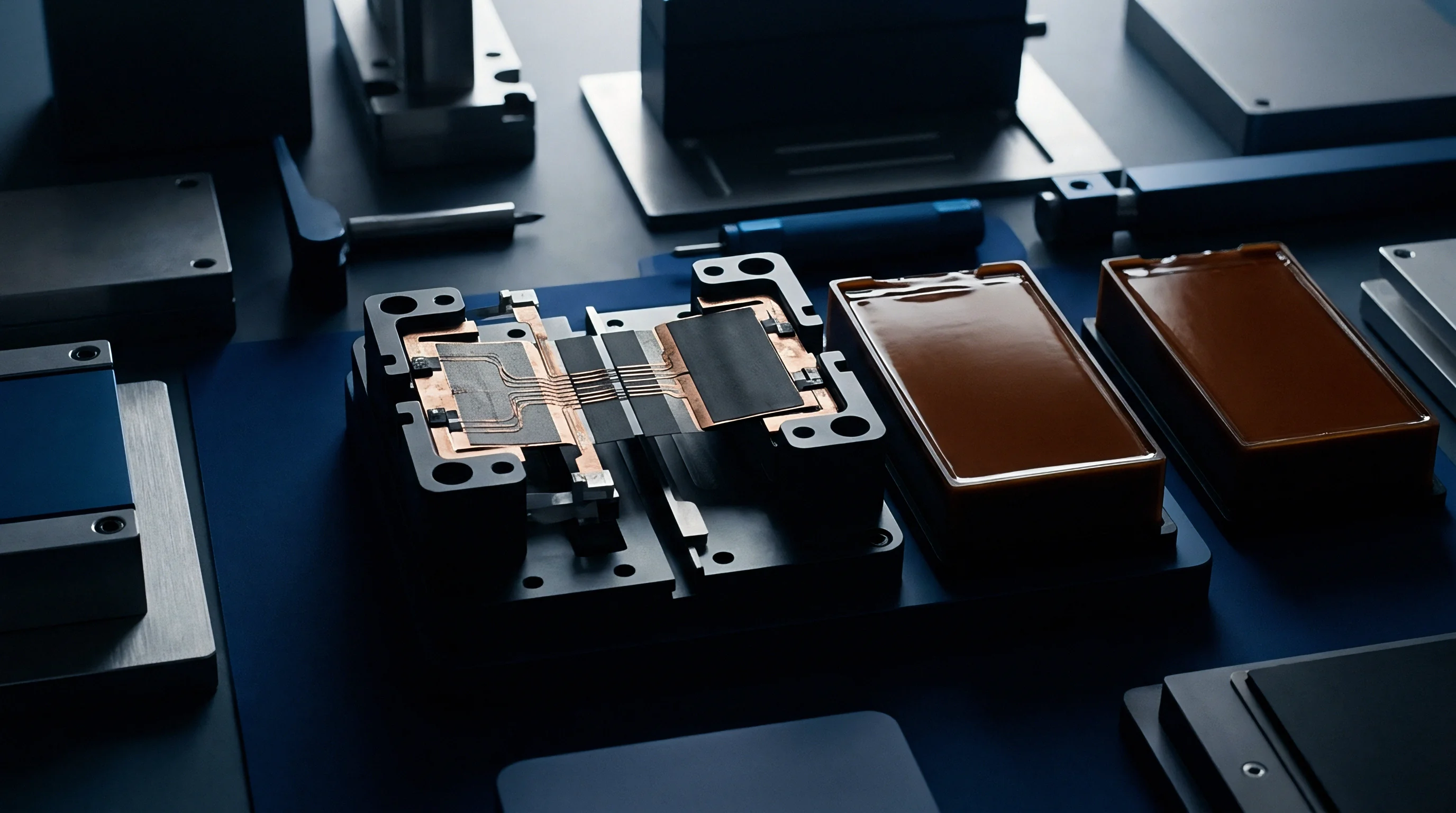
Durable structural bonding between battery cell casings and pack enclosures depends entirely on surface preparation and process control during dispensing. Unmodified aluminum surfaces have low surface free energy, native oxide layers with variable hydration states, and residual stamping oils or processing lubricants. Applying structural adhesives directly onto unprepared metal leads to interfacial moisture accumulation, catastrophic debonding, and poor long-term fatigue resistance.
Establishing strong chemical reactivity requires removing organic contaminants and generating active surface oxides capable of forming covalent bonds with polymer active groups.
Plasma cleaning raises surface energy rapidly. Atmospheric pressure plasma nozzles swept across aluminum bonding tracks remove organic oils through high-energy ion bombardment and localized thermal oxidation. Plasma treatment breaks non-polar hydrocarbon chains, grafting polar hydroxyl, carbonyl, and carboxyl functional groups onto the metal oxide outer skin.
Surface free energy increases from baseline levels below 32 dynes per centimeter up to values exceeding 68 dynes per centimeter, allowing structural adhesives to wet the surface completely without trapping micro-voids.

Plasma Treatment and Contact Angle Metrics
Quality verification on high-speed NPI lines relies on automated contact angle measurement systems. Water contact angles drop from 75 degrees down below 15 degrees following atmospheric plasma treatment. Maintaining process control requires establishing clear upper and lower operating limits for surface treatment speed, plasma power gas flow rates, and nozzle-to-substrate standoff distances.
Standoff variations exceeding 3 millimeters cause dramatic drops in surface activation, resulting in inconsistent bondline wetting and reduced dynamic fatigue strength.
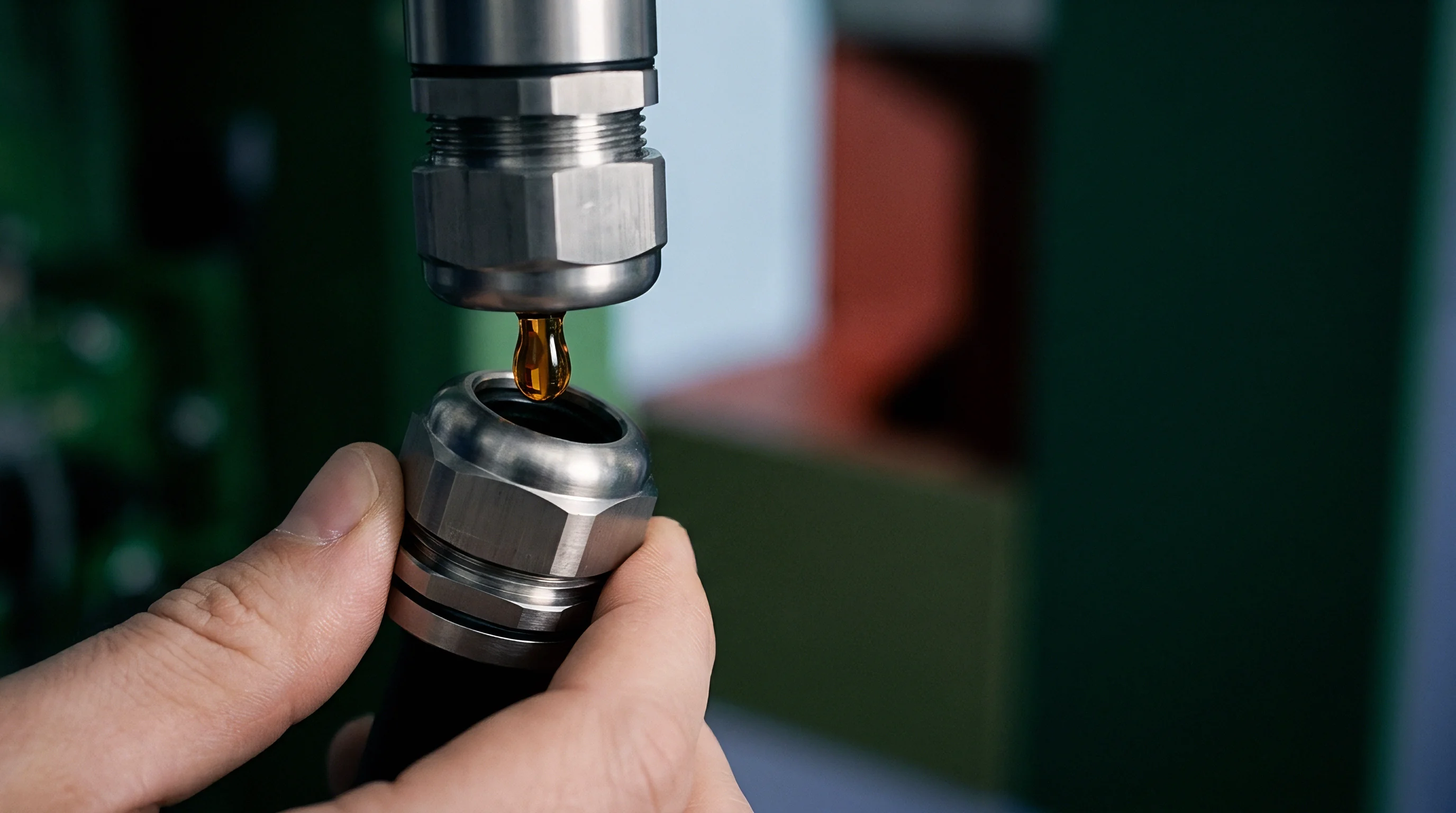
Dispense viscosity governs wet bondline stability. Structural adhesives must maintain thixotropic ratios high enough to prevent sagging after robotic bead application, combined with shear-thinning behavior under high-pressure pump delivery. Controlled viscosity profile parameters prevent bead displacement during high-velocity pick-and-place cell insertion operations.
Encapsulated air bubbles trapped inside adhesive beads during high-pressure meter-mix pumping expand into internal stress risers under fatigue loading, accelerating crack initiation inside the joint bulk resin.

Dispense Tolerances and Gap Control Line Audits
Bondline thickness variance introduces severe local shear fatigue life discrepancies across multi-cell assemblies. When robotic cell placement equipment misaligns cell arrays, bond gap distances shift from nominal 1.0 millimeter dimensions down to 0.2 millimeters or up to 3.0 millimeters across the pack plane. Thin bondlines restrict volumetric strain allowance, increasing localized shear stress under lateral expansion loads.
Thick bondlines lower structural joint stiffness, permitting excessive cell vibration movement under dynamic excitation. Precision fixture tooling and real-time laser displacement tracking maintain dimensional bond gaps within specified tolerances.
- Measure surface energy of raw cell aluminum casings using automated contact angle goniometry prior to dispensing.
- Direct atmospheric plasma nozzles across bonding zones at controlled speeds below 200 millimeters per second.
- Verify open time window of two-component polyurethane before automatic robotic cell placement.
- Measure wet bondline thickness across nine reference points using laser displacement sensors.
- Apply constant clamping force during initial gelation phase to eliminate interfacial air pockets.
Oil residues on cell casings drop surface energy below forty dynes per centimeter and induce adhesive interface failure under low dynamic loads.
Under DIN 6701 Class A1 structural bonding standards, missing pre-treatment validation records invalidates compliance documentation files, requiring full tear-down and structural re-testing of the affected manufacturing lot.


Ledger
Transitioning from mechanical module fastening to cell-to-pack adhesive bonding changes battery manufacturing capital expenditure structures and ongoing operational warranty allocations. Automated adhesive dispensing systems require substantial capital investment in multi-axis robotic gantries, meter-mix-dispense pumps, plasma pretreatment stations, automated vision inspections, and inline atmospheric curing tunnels. Eliminating module housings, busbar flex plates, internal structural frames, and hundreds of mechanical fasteners yields net bill-of-materials savings per pack.
Operational cost evaluations must balance upfront non-recurring engineering tooling expenses against yield risks associated with post-dispense rework limits.
Reworking defective structural adhesive joints poses severe economic challenges on volume assembly lines. Once a cell array undergoes bonding with a fast-curing polyurethane or structural epoxy, removing individual damaged cells requires mechanical wire-saw slicing or localized thermal softening above glass transition points. Chemical solvents capable of dissolving cross-linked thermosetting resins degrade adjacent cell sleeve insulation, aluminum casings, and cooling plate seals.
Unrecoverable cell arrays damaged during structural rework operations increase scrap costs, eroding theoretical bill-of-materials cost advantages if production yields fall below target thresholds.

Capital Expenditure in Automated Dispense Lines
Cure speed dictates line takt time. Fast-reacting structural adhesives achieve green strength within 10 to 15 minutes, allowing downstream pack handling without mechanical clamping fixtures. High reaction rates generate narrow open time windows, where robotic dispensing systems must apply material, position cell arrays, and verify alignment before initial gelation begins.
Exceeding open time limits during line stoppages causes partial cross-linking prior to substrate contact, resulting in poor wetting, weak interfacial bonds, and severe fatigue life degradation under vehicle operating loads. Thermal acceleration through infrared heating arrays speeds up cross-linking but increases capital outlay and floor footprint demands.
Commercial contracts between cell suppliers, adhesive formulators, and OEM battery pack integrators must delineate structural warranty responsibility boundaries. Traditional module designs establish clear responsibility seams: cell makers cover internal electrochemical performance, module builders guarantee structural integrity, and OEM integrators manage vehicle pack mounting. Cell-to-pack integration blurs these boundaries completely.
When structural adhesive fatigue causes joint debonding, disputing parties challenge whether failure stems from cell casing coating inconsistencies, adhesive mixing ratio drift, environmental moisture exposure, or improper chassis flexure assumptions during pack engineering design.

Warranty Allocation across Adhesive Supply Chains
To reduce commercial exposure, tier-1 battery pack manufacturers enforce stringent incoming quality audit standards and boundary conditions within supply agreements. Adhesive formulators must certify volumetric mixing ratio tolerances, viscosity curves, and raw material batch purity before shipping. Battery cell suppliers must guarantee surface coating composition, roughness profiles, and oil contamination limits on aluminum casings.
Pack integrators assume responsibility for maintaining line dispense parameters, ambient humidity levels, and plasma pretreatment validation checks during high-volume production operations.
| Bonding Application Method | Capital Tooling Cost (USD) | Line Takt Time per Pack (Min) | Rework Capability Index | Structural Shear Fatigue Resistance | Primary Warranty Failure Mode |
|---|---|---|---|---|---|
| 2K Automated Liquid Polyurethane Dispense | $1,850,000 | 4.5 | Low (Requires Wire Sawing) | High (Viscoelastic Strain Energy Absorption) | Cohesive Fatigue Micro-Cracking |
| 1K Heat Cured Structural Epoxy Dispense | $2,400,000 | 18.0 | Very Low (Thermal Softening Risks Cell Damage) | Very High (High Modulus Rigid Joint) | Interfacial Debonding from Moisture Ingress |
| Structural Acrylic Liquid Dispense | $1,450,000 | 3.0 | Moderate (Chemical Softening Agents) | Moderate (Susceptible to Thermal Creep) | Thermal Creep Shear Displacement |
| Pre-Applied Structural Acrylic Pressure Tape | $620,000 | 2.0 | High (Manual Peel and Surface Scraping) | Low (Lower Static Shear Yield Strength) | Interfacial Creep Cleavage under Swelling |
Defining clear responsibility seams requires identifying specific structural joint failure mechanisms and mapping them directly back to chemical, mechanical, or operational root causes.
- Adhesive layer cohesive shear fracture occurs when peak vibration stresses surpass the yield limit of the bulk polymer resin.
- Substrate interfacial debonding traces to organic residue contamination or insufficient plasma excitation prior to polymer dispense.
- Thermal stress induced creep fatigue manifests under sustained elevated ambient exposure combined with cell expansion torque.
- Galvanic corrosion at bond perimeters develops when moisture penetrates unsealed adhesive edges joining dissimilar aluminum alloys.
Which countermeasure provides the optimal balance between initial tooling capital expenditure and long-term warranty reserve allocations when structural adhesive shear fatigue thresholds drop under extreme environmental exposure?

Bench
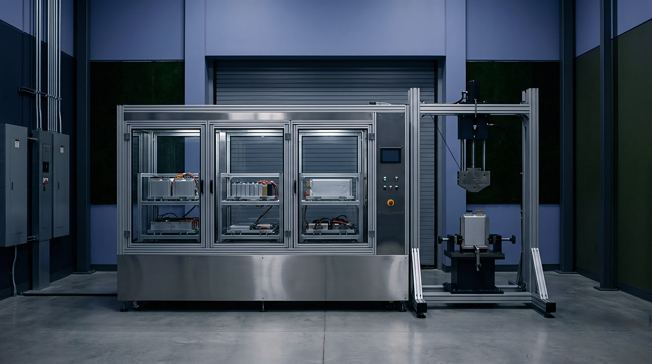
Validating shear fatigue mechanics in integrated cell-to-pack structural joints requires rigorous physical bench testing, dynamic thermal mechanical analysis, and non-destructive evaluation methods. Standard static lap shear tests fail to simulate variable-frequency vibration profiles, swell-induced mean stresses, and moisture-driven interface degradation present in real vehicle operation. Advanced testing protocols combine dynamic mechanical resonance test rigs, high-frequency servohydraulic actuators, environmental humidity chambers, and real-time acoustic emission sensors to capture sub-critical flaw growth before structural joint cleavage occurs.
Incomplete gelation leads to premature structural joint failure. Bench testing setups must reproduce multi-axial stress states observed during pack enclosure torsion. Dual-axis servo-hydraulic test benches apply simultaneous dynamic shear displacement and transverse compressive pre-loads, capturing real-time interaction between cell expansion pressure and vibration fatigue loading.
Testing protocols vary ambient temperature between minus 40 degrees Celsius and plus 85 degrees Celsius while continuously cycling relative humidity to quantify moisture-assisted crack growth rates over extended testing durations.

Resonant Vibration and Accelerated Shear Fatigue Rigs
Accelerated resonance fatigue testing utilizes electrodynamic shakers to excite full-scale cell-to-pack sub-assemblies at fundamental natural frequencies. Monitoring resonance frequency shifts provides early indication of internal structural adhesive damage. As micro-cracks form and propagate through the adhesive matrix, joint stiffness decreases, causing sub-assembly resonant frequencies to drift downward.
Tracking frequency response shifts allows test engineers to construct precise stiffness degradation curves, defining exact cycle counts corresponding to initial damage onset without requiring destructive teardowns.
Ultrasonic inspection techniques enable real-time tracking of bondline structural integrity during dynamic fatigue testing. Phased array ultrasonic testing uses multi-element transducers to map sound wave attenuation through the adhesive layer, producing high-resolution cross-sectional images of the bonded interface. Micro-voids, unbonded areas, and fatigue micro-cracking absorb and reflect ultrasonic energy differently than dense, fully cured polymer resin.
Continuous ultrasonic monitoring reveals crack tip propagation rates across the bondline as dynamic shear cycles accumulate.

Nondestructive Bond Line Quality Inspections
Non-destructive inspections deployed during NPI line bring-up validate dispense accuracy and detect process defects before battery packs leave manufacturing facilities. Active thermography uses flash lamps or induction heating pulses to inject thermal energy into aluminum floor plates, tracking heat diffusion into adjacent adhesive layers using high-resolution infrared cameras. Entrapped air voids and interfacial debonding block thermal conductive pathways, appearing as localized hot spots on thermographic images.
Thermography provides rapid full-field verification of adhesive coverage and bond completeness within automated takt times.
- High frequency resonance testing isolates structural stiffness degradation across bonded cell modules under sinusoidal loading profiles.
- Pulsed ultrasonic phased array scanning maps internal bondline void distributions down to zero point two millimeter acoustic resolution.
- Dynamic mechanical thermal analysis identifies glass transition relaxation peaks under swept temperature profiles from minus forty to eighty degrees Celsius.
In structural fatigue trials evaluating multi-cell block configurations subjected to combined 2.5 g RMS random vibration and cyclic thermal aging, acoustic emission monitoring detected microscopic stress wave pulses originating from micro-crack formation at 1.8 million vibration cycles, 4.2 million cycles before macroscopic joint failure occurred. Acoustic emission transducers mounted along aluminum tray flanges capture high-frequency transient elastic stress waves released by sudden structural micro-fractures inside bulk adhesive resins. Triangulating arrival times across sensor arrays pinpoints exact spatial locations of propagating flaw centers, allowing pack architecture engineers to reinforce high-stress perimeter zones, modify bead geometry dispense paths, and re-engineer joint stress distribution long before committing capital money to volume tooling production.