Determining Initial Mechanical Preload Limits for Prismatic Lithium Ion Cell Modules
Prismatic cell initial mechanical preload limits must balance interfacial contact impedance suppression at 0.15 to 0.35 MPa against EOL structural frame stress.


Swell

Target Preload Ranges and Physical Boundary Limits
Prismatic lithium-ion modules require initial mechanical clamping to maintain electrochemical layer contact, prevent interfacial delamination, and suppress micro-motion during operational vibration. Determining this initial preload involves balancing two opposing mechanical failure modes: interfacial separation at low compression and separator damage or housing deformation under heavy load. Beginning-of-life preload windows for commercial lithium iron phosphate (LFP) and nickel manganese cobalt (NMC) prismatic cells sit between 0.15 MPa and 0.35 MPa of uniform surface pressure across the active face area.
Applying an initial load below 0.10 MPa permits gas to accumulate between electrode layers, raising internal resistance and creating localized current density spikes. Conversely, clamping above 0.50 MPa forces electrolyte out of active electrode pores and risks permanently deforming polyolefin separator membranes.
Cell faces expand during charging, so calculating the required clamping force requires converting target surface pressures into static loads based on face geometry. A standard 280 Ah LFP prismatic cell measuring 174 mm wide by 207 mm high has an active contact area of 0.036018 square meters. Setting an initial nominal preload pressure of 0.20 MPa requires a static assembly force of 7.20 kN per cell face.
Over extended cycling, solid electrolyte interphase buildup and graphite lattice expansion push nominal face pressure higher. At end-of-life, internal stress inside a constant-volume frame reaches 0.85 MPa, elevating total static force against the module end-plate to 30.62 kN. Frames designed without accounting for this force growth suffer bolt yield, tie-rod stretch, or side-wall buckling.
| Cell Chemistry | Nominal Capacity (Ah) | Target Initial Preload (MPa) | Initial Clamp Force (kN) | Peak EOL Pressure (MPa) | Separator Yield Limit (MPa) |
|---|---|---|---|---|---|
| LFP (Graphite Anode) | 280 | 0.20 | 7.20 | 0.85 | 2.10 |
| NMC622 (Graphite Anode) | 120 | 0.25 | 5.40 | 0.95 | 1.85 |
| NMC811 (Graphite Anode) | 150 | 0.30 | 7.10 | 1.20 | 1.70 |
| NMC811 (Si-Blend Anode) | 180 | 0.35 | 8.80 | 1.60 | 1.50 |
Initial clamping forces flatten natural pouch and hard-case surface undulations created by manufacturing variations in the internal jelly-roll or electrode stack. Flatness tolerances across high-capacity prismatic cell faces typically range from 0.3 mm to 0.8 mm. Without preload, high spots on adjacent cases absorb localized assembly loads while low spots make no mechanical contact at all.
Localized pressure spikes exceeding 1.0 MPa degrade separator porosity in tight spots, while adjacent uncompressed areas trap gas, accelerating active lithium loss and impedance growth.
Engineering practice dictates sizing module end-plates to deflect less than the elastomeric pad expansion allowance under maximum state-of-charge growth.

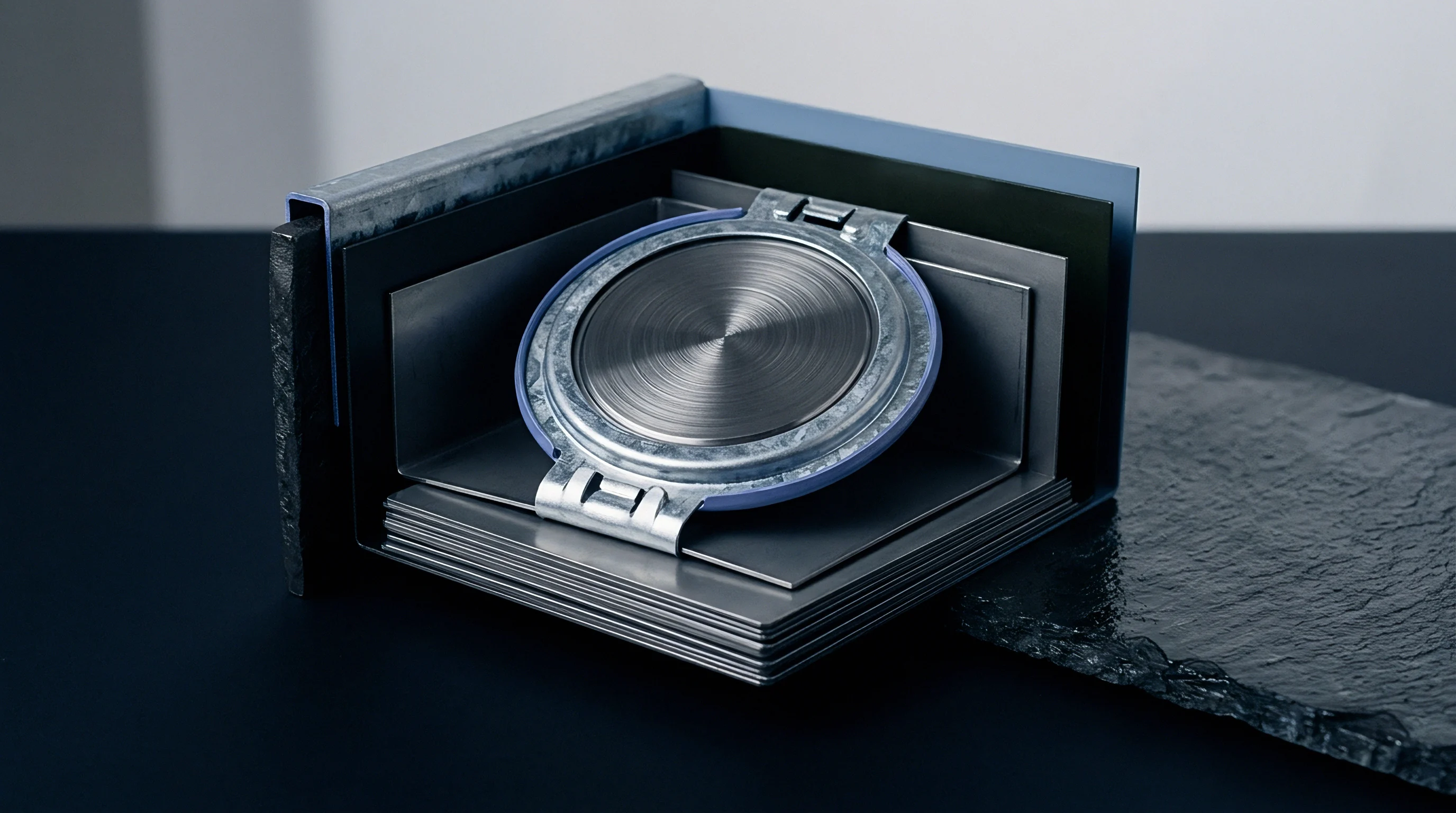
Kinematics

Electrochemical Swelling and Solid Phase Mechanics
Lithium intercalation into graphite anodes causes macro-scale volumetric expansion of the electrode stack during every charge cycle. Intercalation expands the graphite unit cell volume by approximately 10 percent at full state of charge. When silicon is blended into the graphite matrix to boost energy density, volumetric strain increases significantly, reaching 300 percent expansion at the particle level for pure silicon domains.
Reversible breathing occurs during each charge-discharge cycle, causing cell thickness to fluctuate dynamically. Irreversible expansion accumulates across hundreds of cycles as side reactions continuously consume inventory and generate thick passivation films on anode particle surfaces.
An initial mechanical preload of 0.20 MPa reduces internal contact impedance by up to 14 percent during the first five hundred discharge cycles.
Maintaining mechanical constraint during continuous volume changes forces active material particles into continuous physical contact, preserving conductive pathways through the carbon black matrix so impedance does not spike from layer separation. Miscalculating initial preload triggers several primary degradation paths across module operational life.
- Separator pore collapse occurs when initial clamp pressure combined with peak state-of-charge expansion exceeds the compressive yield strength of the polyolefin membrane, choking ion transport.
- Anode delamination develops when insufficient mechanical preload fails to counteract cyclic electrode breathing, allowing current collector foils to separate from coated slurry layers.
- Aluminum housing deformation happens when unconstrained end-of-life swelling force drives the deep-drawn cell enclosure past its plastic deformation threshold, rupturing insulation barriers.
- Lithium plating acceleration emerges when non-uniform interface pressure creates high-resistance localized zones, forcing ionic current into adjacent low-pressure regions during fast charging.
As high-nickel formulations incorporate higher percentages of silicon to hit energy density targets, initial mechanical preload design becomes sensitive to state-of-charge operational limits. Unconstrained silicon-blend cells expand up to 8 percent in overall stack thickness over 1,000 cycles, compared to 2 to 3 percent for conventional graphite anodes. Clamping these modules in rigid constant-gap fixtures causes internal stress to double within the first 200 cycles, driving rapid electrolyte displacement and dry-spot formation near the center of the electrodes.
It remains unclear whether real-time acoustic emission monitoring during high-rate fast charging can accurately isolate active material particle fracture from global housing strain.


Constraint

Structural Frame Stiffness and Compression Pad Mechanics
Module mechanical design utilizes two distinct containment strategies: rigid constant-volume containment and compliant spring-loaded or foam-padded constraint. Rigid containment uses aluminum or steel side plates welded directly to thick end-plates, fixing the total stack width throughout pack life. Constant-volume structures simplify assembly but force internal pressures to scale linearly with irreversible cell swelling.
Compliant containment integrates microcellular polyurethane foam, silicone elastomeric sheets, or metallic spring washers between cells, absorbing volumetric expansion while dampening initial force spikes.
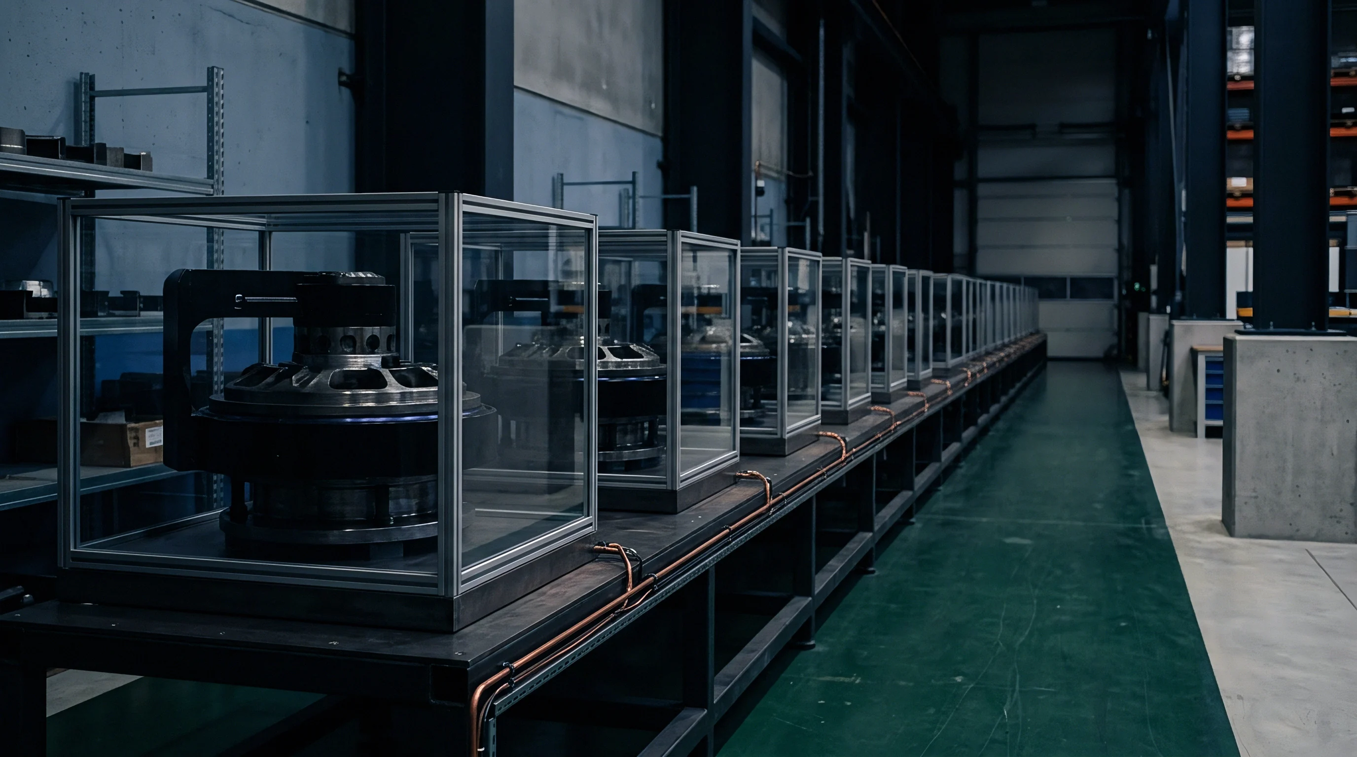
Why Do Fixed-Gap Containment Systems Accelerate Separator Creep?
Fixed-gap enclosures offer zero mechanical compliance as cells expand. When solid electrolyte interphase growth increases stack thickness against rigid metal frames, the resulting compressive stress transfers directly into the separator. Polyolefin separators undergo permanent viscoelastic creep under sustained loads above 1.0 MPa at elevated operating temperatures.
This creep thins the membrane, shortening the ionic path length while reducing internal electrolyte retention, which leads to premature capacity loss and short-circuit risks.
Compliance with UN 38.3 vibration testing requires module end-plates to retain structural integrity without loosening bolt torque below specified clamping minimums.
| Material Type | Density (kg/m³) | Initial Spring Rate (kPa/mm) | Compression Set at 70°C (%) | Thermal Conductivity (W/m·K) |
|---|---|---|---|---|
| Microcellular Polyurethane | 400 | 120 | < 5.0 | 0.08 |
| Silicone Foam | 350 | 85 | < 8.0 | 0.12 |
| Closed-Cell EPDM Rubber | 500 | 210 | 18.5 | 0.15 |
| Aerogel Composite Pad | 220 | 310 | < 3.0 | 0.02 |
Selecting continuous inter-cell padding requires evaluating stress relaxation over multi-year warranty periods, as elastomeric pads experience compression set. High operating temperatures inside battery packs accelerate polymer chain relaxation, reducing effective preload force over time. Microcellular polyurethane pads retain spring force effectively under cyclic loading, losing less than 5 percent of nominal thickness after long-term thermal aging.
Closed-cell EPDM displays higher compression set, losing clamping force rapidly during high-temperature operational profiles.
Calculating bolt size and torque specifications for fasteners that carry swelling forces requires determining joint stiffness ratios between structural end-plates, tie-rods, and compressed cell stacks. Structural side-bands welded to end-plates must withstand combined pre-tensioning force plus peak dynamic shock loads during crash safety events. Under ISO 12405-4 Annex C, structural containment hardware must prove zero permanent plastic deformation after experiencing peak dynamic shock loads combined with maximum state-of-charge swelling forces.


Metrology

Bench Verification and Load Cell Calibration Workflows
Accurate verification of initial mechanical preload requires specialized test rigs capable of measuring two-dimensional pressure distributions across full cell active faces. Multi-axis load cells mounted behind compression plates measure total applied force, while tactile pressure-mapping films establish interface contact uniformity. Single-point load sensors fail to identify edge-loading phenomena caused by end-plate flexure during assembly clamping.
Assembly procedures verify that pressure gradients remain within 15 percent of nominal target pressure across the entire cell surface.
Measuring compression mechanics during module validation relies on strict assembly sequencing and load cell calibration to isolate component dimensional tolerances.
- Position tactile pressure sensors between adjacent cell faces inside the uncompressed stack assembly frame.
- Apply uniform hydraulic pressure until load cell displays target initial preload value.
- Torque module tie-rod fasteners to designated specification using calibrated multi-spindle drivers.
- Perform baseline electrical impedance spectroscopy to confirm uniform inter-layer electrochemical contact.
- Soak assembled module at upper storage temperature for twenty-four hours to measure initial compression set relaxation.
Calibrating load sensors at operational thermal boundaries prevents transient expansion spikes from masking permanent elastomeric set loss.
Manufacturing stackups introduce dimensional variations from cell casing thickness tolerances, insulation film variations, and end-plate machining limits. In a 12-cell module stack with an individual cell thickness tolerance of +/- 0.2 mm, total stack length varies by up to +/- 2.4 mm prior to compression. Assembled modules relying on fixed physical stroke distance experience severe preload variations, where tight stacks receive excessive initial force while loose stacks remain under-clamped.
Assembly lines require force-controlled clamping systems rather than position-controlled stroke stops to guarantee precise initial preload application.
Cell thickness variations exceeding published datasheet tolerances stem from natural batch variations in cathode slurry coat weight.


Exposure

Warranty Liabilities and Regulatory Safety Certification
Incorrect initial mechanical preload specification introduces commercial risks spanning product safety certification, warranty claims, and regulatory approval. Module design dictates compliance with transport regulations, UN 38.3 test series requirements, and international safety standards such as IEC 62660-3 and UL 2580. Inadequate initial preload allows cell movement under UN 38.3 vibration (Test 3) and mechanical shock (Test 4), causing insulation fretting, cooling plate adhesive bond failure, and terminal busbar fatigue cracking.
Over-clamping shortens total cycle life.
Because void formation accelerates active lithium loss, modules that fail to achieve promised cycle life due to improper preload engineering expose pack integrators to early warranty replacement costs. Under the European Union Battery Regulation (2023/1542), manufacturers carry extended producer responsibility, including mandatory durability and performance documentation. Sourcing agreements define mechanical integration requirements, transferring liability to integrators who fail to maintain cell manufacturer mechanical preload specifications.
Uncontrolled mechanical swelling damages cooling plate adhesive bonds and compromises pack thermal management.
Because thermal runaway spreads through contact, inter-cell compression pads serve a dual function in modern pack design, acting as mechanical expansion dampers and high-temperature thermal barriers. Excessive initial compression reduces pad thickness and increases density, elevating material thermal conductivity and compromising inter-cell thermal propagation resistance during single-cell thermal runaway events. Qualification dossiers require full mechanical stress verification alongside thermal abuse validation.
- Module strain certification validates that structural frame members remain within elastic limits across all operational temperatures and states of charge.
- Fastener torque traceability links automated spindle rundown records with individual module serial numbers during factory assembly.
- EOL expansion modeling combines mechanical pad creep data with electrochemically driven swelling projections to guarantee end-of-life pack containment.
- Thermal runaway containment audit verifies that fully compressed inter-cell fire barriers retain sufficient thermal insulation under peak EOL mechanical pressure.
Insufficient initial preload allows interface micro-motion during transport, causing protective pouch foil wear, electrolyte leakage, and field recall liability.