Prismatic Cell Swelling Kinetics and Mechanical Module Clamping Limits
Prismatic cell swelling kinetics require module clamping designs that balance initial foam pre-load against end-of-life separator compression limits.


Intercalation
Lithium migration into host electrode structures drives dimensional expansion during every charge cycle. In prismatic hard-case formats, this volumetric change acts directly against rigid aluminum or steel container walls. Graphite anodes exhibit a unit cell volume growth of approximately ten percent when fully lithiated to a stoichiometry of LiC6.
Cathode materials respond differently: lithium iron phosphate actually contracts during delithiation, whereas high-nickel layered oxides undergo isotropic lattice compression upon initial charge followed by structural collapse at high states of charge. Net cell breathing reflects the coupled sum of these crystallographic shifts. When a cell charges, the stack expands across its thickness dimension.
Width and height remain largely constrained by internal current collector foils and wound or stacked separator geometry, projecting virtually all volumetric deviation outward along the face normal to the electrode sheets.
Reversible expansion alternates with every full charge and discharge sequence. Unconstrained cells breathe between one and three percent of total stack depth across standard operating state-of-charge windows. Cyclic mechanical stress induces internal shear forces across the active material layers.
Over hundreds of cycles, these forces micro-fracture binder matrix bonds, disintegrate secondary active material particles, and expose fresh transition metal surfaces. These newly exposed surfaces consume active lithium ions from the electrolyte to form additional solid electrolyte interphase layers ~ a parasitic reaction that constitutes the baseline component of permanent growth.

Solid Phase Lattice Dynamics
Crystallographic dimensional shifts govern the initial mechanical response of the electrode stack. During lithiation, inserting lithium ions between graphene planes expands the inter-planar spacing from 0.335 nanometers to 0.370 nanometers, driving a macro-level thickness increase across the anode composite. Lithium iron phosphate cathode particles transition between the triphylite phase and the heterosite phase.
The unit cell volume of fully delithiated iron phosphate is 6.8 percent smaller than its lithiated state, which partially counteracts anode expansion during charge. High-nickel layered oxides show a different pattern: nickel-rich chemistries experience an initial c-axis lattice expansion during lithium extraction, followed by an abrupt c-axis contraction when state of charge exceeds eighty percent. This non-linear crystallographic behavior creates localized mechanical stress peaks within the cathode coating.
| Chemistry Platform | Reversible Swell (100% SOC) | Baseline Irreversible Swell (1000 Cycles) | Peak EOL Swell Rate (3000 Cycles) | Internal Gas Generation Potential |
|---|---|---|---|---|
| Lithium Iron Phosphate (LFP / Graphite) | 1.2% to 1.8% | 3.5% to 5.0% | 8.0% to 12.0% | Low to Moderate (Carbonate breakdown) |
| Nickel Manganese Cobalt 622 (NMC-622 / Graphite) | 2.0% to 2.8% | 2.5% to 4.0% | 6.0% to 9.5% | Moderate (Transition metal dissolution) |
| Nickel Manganese Cobalt 811 (NMC-811 / Graphite-Silicon 5%) | 3.2% to 4.5% | 5.5% to 8.5% | 12.5% to 18.0% | High (Particle cracking & severe gassing) |
Cell geometry dictates how microscopic lattice changes convert into external force vectors. Prismatic cells concentrate thickness growth on their broadest faces. Because the narrow side edges are mechanically rigid, the jellyroll or stacked electrode group is forced to buckle inward or push outward against the large flat side plates.
Silicon anode blends amplify this effect. Incorporating five weight-percent silicon into a graphite matrix increases localized particle volume changes up to three hundred percent during lithiation. Even low substitution ratios raise reversible stack swelling from under two percent to over four percent per cycle.
Silicon particle cracking exposes unpassivated surfaces, driving irreversible lithium consumption and rapid solid-phase accumulation.

Electrolyte Degradation and Permanent Gas Buildup
Alongside solid phase accumulation, chemical breakdown pathways inside the sealed enclosure produce non-condensable gaseous species. Carbonate solvents decompose at extreme electrode potentials and elevated temperatures, yielding carbon dioxide, carbon monoxide, ethylene, and hydrogen gas. Gassing increases internal hydrodynamic pressure within the prismatic enclosure.
In flexible pouch cells, gassing expands the outer foil envelope uniformly, but in rigid prismatic cans, gas bubbles accumulate between internal separator and electrode layers. These gas pockets displace liquid electrolyte, creating localized dry spots that cut off ionic transport pathways and cause current density spikes in adjacent wet zones.
Elevated current densities accelerate localized lithium plating on anode surfaces. Plated metallic lithium forms mossy or dendritic structures that increase overall stack thickness far faster than uniform interphase growth. This plating is irreversible and permanently alters internal stack geometry.
Thermal cycling further intensifies gassing kinetics: running a prismatic cell at 45 degrees Celsius doubles the electrolyte decomposition rate compared to operation at 25 degrees Celsius. Higher temperatures also accelerate transition metal dissolution from cathode active materials. Dissolved manganese or nickel ions migrate across the separator and deposit on the anode, where they break down the passivating interface layer.
Continuously repairing this layer consumes active lithium, generates gas, and accelerates irreversible thickness growth.
Solid-state volume changes during intercalation generate cyclic breathing stress, while electrolyte breakdown products create permanent structural expansion over thousands of charge-discharge cycles.
Internal stack swelling remains below four percent over three thousand cycles when held under ideal bench conditions. Factory bench protocols apply a constant mechanical restraint of 0.3 megapascals using calibrated pneumatic press frames in climate-controlled rooms. These test conditions eliminate localized stress concentrations, clear gas pockets from active interfaces, and prevent current density hotspots.
Pack housing in production rarely matches these bench environments. While ideal constant-pressure test curves are used to justify nominal thickness specifications, module builders have to design for actual mechanical constraints that shift from low initial pre-load to high end-of-life pressure as cells age inside rigid frames.


Padding
Compression materials installed between individual prismatic cells control structural force distribution across the operating life of a pack. Elastomeric buffers absorb reversible cycling swell and compensate for manufacturing tolerances in cell thickness, end plate placement, and assembly stackups. Without intermediate compressible layers, direct cell-to-cell contact converts minor dimensional increases into severe mechanical pre-load spikes.
Direct contact between aluminum cell cans also risks localized wall fretting, insulation film breakdown, and premature assembly failure.
Foam selection directly dictates pack service life. Microcellular polyurethane and cross-linked silicone foams serve as the primary inter-cell buffer materials. These materials exhibit non-linear stress-strain relationships characterized by an initial soft linear region, a wide plateau phase, and a sharp densification region.
Engineering a module clamping scheme requires placing the compression material operating window entirely within its plateau region throughout the pack service life. If stack expansion drives the buffer material into its densification zone, the spring rate increases by an order of magnitude, transferring massive mechanical forces directly into module end plates and neighboring cells.

Stress Relaxation and Creep Kinetics
Polymers subjected to sustained compressive strain experience internal molecular realignments that reduce force over time. Microcellular polyurethane foam compressed to thirty percent strain loses twenty to thirty-five percent of its initial reaction force within twenty-four hours at room temperature. Elevated temperatures accelerate this degradation: at 50 degrees Celsius, sustained strain induces polymer chain scission and cross-link degradation, causing permanent compression set.
This permanent set reduces the foam’s ability to exert adequate holding force when the cell contracts during discharge or cool-down cycles.
Dynamic cycling compounds static relaxation effects, and preload can decay significantly within weeks. Cyclic compression from cell breathing causes mechanical fatigue in the open-cell or microcellular strut network, where strut micro-cracking lowers the effective compression modulus of the pad over thousands of charge-discharge cycles. Designing a clamping system solely around fresh material datasheets introduces systemic failure risks.
Initial clamping pre-load must sit high enough to compensate for thermal relaxation and mechanical fatigue, yet low enough to prevent immediate cell damage or frame yield during peak operating conditions.
- Microcellular Polyurethane Compression Set manifests as permanent foam height loss following prolonged thermal exposure under load, reducing minimum retention pressure at low states of charge.
- Elastomeric Stress Relaxation Decay reduces effective clamping force over time, allowing individual cells to shift inside the module frame during severe vibration or impact events.
- Buffer Densification Spikes occur when cell swelling exhausts inter-cell foam porosity, transmitting unattenuated expansion forces directly into structural module walls.
- Thermal Expansion Mismatch Strain generates continuous shear stresses across adhesive interfaces bonding compression pads to cell sidewalls during thermal transients.

Microcellular Polyurethane and Silicone Elastomer Selection
Material choices directly set the mechanical impedance of the cell stack. Open-cell microcellular polyurethanes provide predictable compression behavior and high energy absorption at room temperature, with a fluid-permeable cellular matrix that allows air to escape smoothly during rapid cell expansion. Closed-cell silicone foams exhibit superior thermal stability across broad operating ranges from minus forty degrees Celsius to eighty degrees Celsius.
Silicone materials maintain constant force-deflection profiles over extended thermal aging cycles, though they display lower tear resistance and higher raw material costs than polyurethane options.
Foam thickness selection requires balancing volume efficiency against mechanical travel. Standard prismatic cell layouts employ buffer pads with uncompressed thicknesses ranging between 1.0 millimeter and 3.0 millimeters. A 2.0-millimeter pad operating at thirty percent nominal pre-compression provides 0.6 millimeters of initial travel reserve per cell face.
In a twelve-cell module, cumulative nominal pad travel totals 7.2 millimeters across the stack length. Manufacturing tolerances compound across this stack: cell thickness tolerances of plus or minus 0.3 millimeters per cell accumulate to plus or minus 3.6 millimeters across twelve cells, consuming half of the available mechanical compensation range before accounting for operational swelling.
Matching foam stiffness to the non-linear growth curve of the cell preserves separator integrity across the operating life of the pack.
Proper pad specification balances material stiffness against maximum allowable cell sidewall force without exceeding structural limits over decades of operation.


Rig
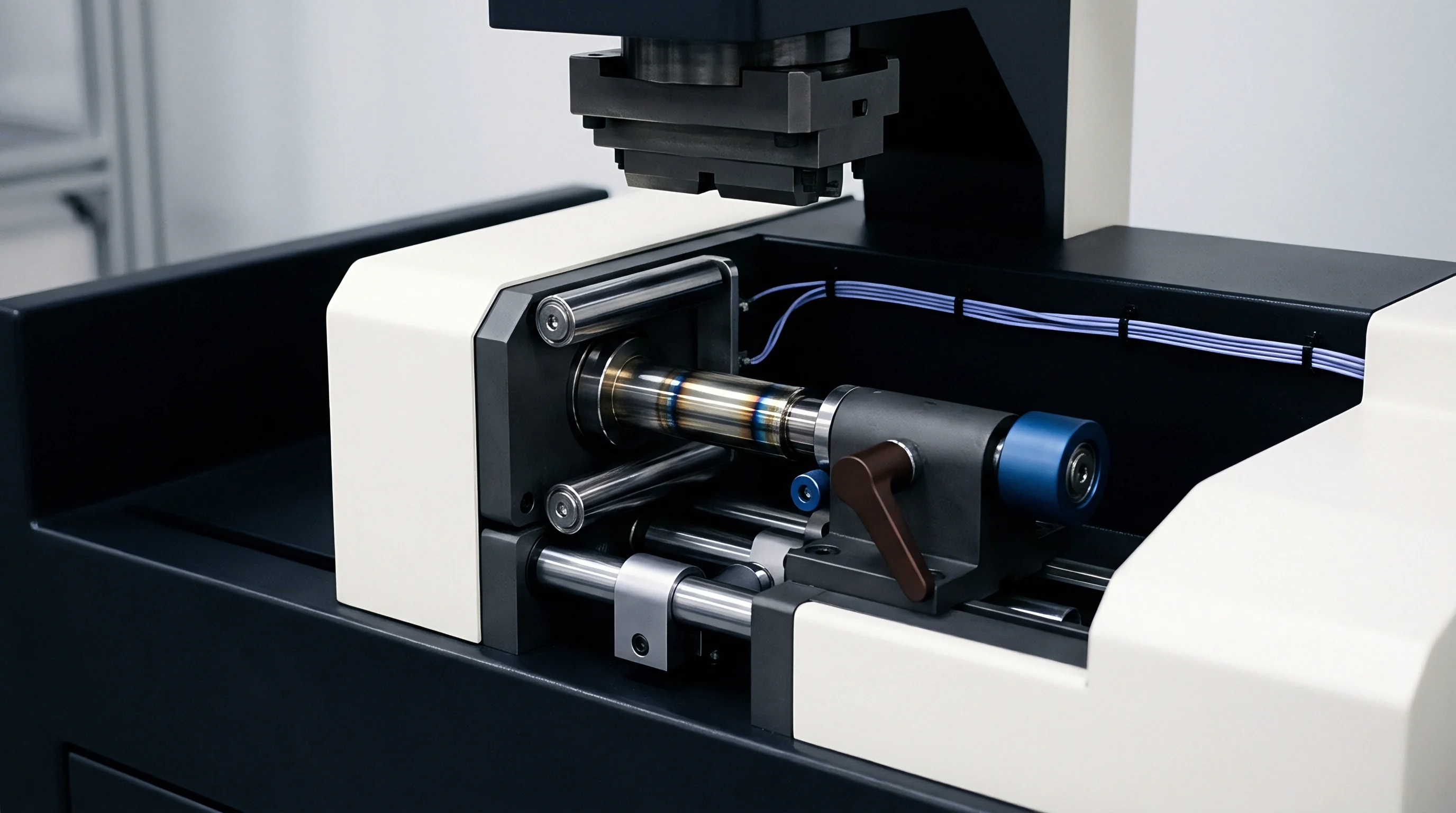
Evaluating swelling forces under true module conditions requires specialized laboratory test fixtures. Test frames must isolate cell-level volumetric changes from fixture compliance, as standard material testing machines equipped with universal load cells often introduce frame flexure that distorts displacement readings. High-precision characterization relies on double-ended rigid tie-bar fixtures instrumented with temperature-compensated strain gauge load washers and linear variable differential transformers across every cell face.
Fixed-gap testing modes maintain rigid fixture dimensions, forcing cell swelling to manifest entirely as measurable clamping pressure escalation. Constant-force testing modes adjust fixture dimensions to hold stack pressure constant while recording absolute thickness expansion. Fixed-gap conditions simulate rigid module architectures bounded by high-stiffness end plates and side extrusions, whereas constant-force conditions mirror spring-loaded or compliance-optimized module designs.
Data captured across both testing regimes forms the empirical foundation required to construct predictive mechanical lifetime models.
Are Separator Pore Closures Irreversible below One Megapascal?
Separator structural changes depend heavily on applied pressure and peak operating temperature. Polyolefin wet-process separators feature sub-micron porous networks engineered to pass lithium ions while insulating electrode layers electrically. Applying sustained mechanical compression forces the polymer fibril matrix to compress.
When mechanical pressure reaches 0.8 to 1.2 megapascals, localized plastic deformation of the separator wall begins. Pore collapse reduces effective porosity, restricts electrolyte flow channels, and increases tortuosity across the separator thickness.
The presence of elevated temperature changes the mechanics substantially. Test data reveals that applying 1.0 megapascal of uniform pressure at 25 degrees Celsius causes an initial five to eight percent reduction in separator ionic conductivity. This change remains largely elastic and recovers when pressure drops.
However, combining 1.0 megapascal pressure with 55 degrees Celsius temperatures causes irreversible thermal creep of the polyolefin fibrils, and closed pores fail to reopen upon load removal. Permanent porosity loss increases internal cell impedance, drives localized overpotentials during high-rate charging, and creates conditions favorable for lithium plating along electrode margins.

Worked Clamping Arithmetic and Impedance Escalation
Quantifying module clamping dynamics requires walking through stack arithmetic for a representative module build. Consider a module comprising twelve 280-ampere-hour prismatic lithium iron phosphate cells connected in series. Initial nominal dimensions of each cell measure 72.0 millimeters in thickness, 174.0 millimeters in width, and 207.0 millimeters in height.
Active electrode contact area on the broad face measures 170.0 millimeters by 200.0 millimeters, yielding an effective surface area of 34,000 square millimeters (0.034 square meters).
Inter-cell buffer pads measure 2.0 millimeters in uncompressed thickness. The pad material exhibits a non-linear spring profile defined by empirical curve fit: pressure P in megapascals equals 0.05 times e to the power of (6.0 times strain epsilon), valid for strains between zero and 0.50. The module enclosure employs rigid aluminum end plates secured by structural side straps.
The total compliance of the enclosure frame, including side strap elasticity and end plate bending, yields an effective module spring rate of 85,000 Newtons per millimeter.
- Calculate initial module assembly stack length without compression: twelve cells at 72.0 millimeters plus thirteen buffer pads at 2.0 millimeters equals 890.0 millimeters total uncompressed length.
- Apply initial assembly pre-load during manufacturing by compressing the stack to a target frame length of 882.2 millimeters, imposing 7.8 millimeters of total compression across thirteen pads (0.60 millimeters compression per pad, corresponding to a nominal strain of 0.30).
- Determine initial pad pre-load pressure: P equals 0.05 times e to the power of (6.0 times 0.30), yielding 0.302 megapascals. Initial force per cell face equals 0.302 megapascals times 34,000 square millimeters, resulting in 10,268 Newtons.
- Model end-of-life unconstrained cell swelling at 8000 cycles, assuming an irreversible cell thickness increase of 6.0 percent (4.32 millimeters per cell) plus a peak reversible cycling swell of 1.5 percent (1.08 millimeters per cell), yielding a potential total expansion of 5.40 millimeters per cell face if unconstrained.
- Calculate total stack expansion potential across twelve cells: twelve times 5.40 millimeters equals 64.8 millimeters of unconstrained dimensional growth.
- Solve for true final stack equilibrium length by equating compression pad force growth to enclosure frame deformation force. Unconstrained stack growth compresses both the pads and deflects the enclosure frame.
- Calculate equilibrium frame deflection and pad strain: frame deflection absorbs 0.72 millimeters of movement, resulting in a net compression displacement of 64.08 millimeters absorbed by the thirteen buffer pads (4.93 millimeters additional compression per pad).
- Determine final end-of-life pad strain: initial strain 0.30 plus additional strain (4.93 divided by 2.0, equaling 2.465), which exceeds physical pad limits, driving the foam into total densification where effective thickness compresses down to 0.40 millimeters (80 percent strain).
- Calculate final end-of-life stack clamping pressure at total densification, where pad compression modulus transitions to solid elastomer behavior (effective modulus E equals 150 megapascals): peak force reaches 41,200 Newtons, generating a sidewall pressure of 1.21 megapascals.
| Applied Pressure (MPa) | Separator Thickness Loss (%) | 1kHz AC Impedance (mΩ) | DC Internal Resistance 10s (mΩ) | Ionic Conductivity (mS/cm) |
|---|---|---|---|---|
| 0.10 (Minimum Preload) | 0.0% | 0.182 | 0.410 | 1.25 |
| 0.30 (Nominal Target) | 1.5% | 0.180 | 0.405 | 1.24 |
| 0.60 (Mid-Life Target) | 4.2% | 0.185 | 0.422 | 1.18 |
| 1.00 (EOL Maximum Limit) | 9.8% | 0.198 | 0.468 | 1.05 |
| 1.50 (Over-Pressure Severity) | 18.5% | 0.235 | 0.590 | 0.82 |
Rising internal resistance directly cuts pack power output and increases heat generation during fast-charge operations. When clamping pressure scales from 0.30 megapascals to 1.50 megapascals, 10-second DC internal resistance rises over 45 percent. Increased resistance causes higher internal I-squared-R heat generation during high-rate current pulses.
Heat generation accelerates chemical degradation reactions, creating a damaging feedback loop between thermal stress, gassing, mechanical swelling, and separator compression.
At 25 degrees Celsius, a sustained clamping force of 1.2 megapascals reduces separator ionic conductivity by 18 percent over 500 hours of continuous exposure.
Tracking expansion curves across 280-ampere-hour cell production lots isolates batch-to-batch variation. Fixture failures occur when unvetted cell lots exceed manufacturer swell estimates by eighty percent, bending 25-millimeter steel tie rods and locking data acquisition rigs. Baseline cell data published by suppliers frequently omits batch variance parameters, forcing integration engineering teams to absorb fixture rebuild costs during qualification programs.


Frame
Module structural components must contain cumulative cell expansion forces while maintaining assembly envelope dimensions. Structural designs employ aluminum alloy extrusions, stamped steel plates, or composite wraps to enclose the cell array. End plates absorb central point loads transmitted through the cell faces and transfer these forces into side covers, tie rods, or battery pack housing cross-members.
Excessive end plate flexure leads to uneven pressure distribution across the broad face of the cell.
When end plates bend under load, they concentrate mechanical pressure around the perimeter of the cell face while relieving pressure across the center. These pressure gradients induce non-uniform current density distributions across active electrode surfaces. Central regions with lower pressure experience localized electrode spacing increases, higher electrolyte resistance, and accelerated capacity fade.
Edge regions subjected to high pressure suffer separator crush and localized lithium plating. Structural end plate design must limit central deflection to less than 0.5 millimeters under peak end-of-life swelling loads.

Structural End Plate Deflection and Tie Rod Tensioning
End plates act as beams supported by side covers or tension tie rods. Beam flexure formulas demonstrate that central deflection scales with the fourth power of span length and inversely with the moment of inertia. Increasing cell width or stack height without expanding end plate thickness causes rapid deflection growth.
Structural ribs, variable-thickness cross sections, and high-yield aluminum alloys control bending strain without introducing excessive mass into the battery system.
| Material & Structural Profile | Thickness (mm) | Yield Strength (MPa) | Peak Deflection (mm) | Structural Weight (kg) |
|---|---|---|---|---|
| Cast Aluminum ADC12 Flat Plate | 18.0 | 160 | 1.42 | 2.15 |
| Extruded Aluminum 6061-T6 Ribbed | 12.0 | 275 | 0.38 | 1.45 |
| High-Strength Stamped Steel S500MC | 4.5 | 500 | 0.45 | 1.82 |
| Carbon Fiber Reinforced Epoxy Matrix | 6.0 | 850 | 0.22 | 0.68 |
Tie rods and side straps maintain continuous axial tension on the module stack. Steel side straps laser-welded to aluminum end plates represent a common high-density structural architecture. Strap weld joints must endure dynamic fatigue loading caused by thermal expansion and cyclic cell breathing.
Weld joints experience combined shear and tension loads. If peak stack pressure generates tensile stresses exceeding strap material yield strength, permanent elongation occurs. Strap elongation reduces module pre-load, causing cells to loosen during low state-of-charge conditions.
- End Plate Moment Deflection Analysis verifies that structural member bending stiffness prevents edge-concentrated pressure zones across cell faces.
- Tie Rod Pre-Tension Verification confirms that fastener pre-load exceeds maximum operating swelling force to prevent joint separation.
- Side Strap Weld Fatigue Sizing calculates allowable shear stresses across laser-welded joints subjected to millions of low-amplitude breathing cycles.
- Thermal Interface Shear Evaluation calculates cross-sectional displacement limits to prevent thermal glue delamination along bottom cooling plates.

Thermal Interface Material Shear Strain under Expansion
Heat transfer between prismatic cells and bottom liquid cooling plates relies on structural thermal adhesives or gaps-filling pads. As cells swell and contract, individual cell cans move relative to the fixed module baseplate. Accumulating cell thickness changes drive longitudinal displacement along the stack axis.
Outer cells experience maximum relative displacement relative to the central module anchor point. This movement imposes heavy shear strain on the intermediate thermal interface layer.
Thermal interface materials have a finite strain capacity before suffering cohesive failure or adhesive debonding. Standard structural polyurethane adhesives provide ultimate shear strain limits between 50 and 150 percent before micro-cracking initiates. If a 1.5-millimeter adhesive layer absorbs 2.0 millimeters of cumulative lateral cell displacement, shear strain reaches 133 percent.
Cohesive failure inside the thermal adhesive introduces air gaps between the cell bottom and cold plate. These air gaps drastically reduce thermal conduction pathways, causing cell operating temperatures to surge during fast-charging operations.
Exceeding the maximum allowable sidewall deflection specified in IEC 62660-3 voids compliance certification for mechanical integrity under impact conditions.
Specifying microcellular silicone pads prevents the compression set observed in standard polyurethane formulations during thermal shock tests. Designing module end-plates around peak solid-state volume change rather than nominal room-temperature dimensions prevents mechanical failures during high-temperature validation trials. Designing rigid enclosures requires evaluating long-term mechanical strain limits for every structural component in the module assembly.
Does the cumulative thermal expansion of side straps match cell stack growth across winter operating limits without inducing structural joint separation?


Paperwork
Commercial contracts and cell datasheets often misalign regarding mechanical expansion limits. Cell suppliers routinely publish nominal thickness dimensions valid only for fresh, uncycled cells measured under light laboratory pre-loads. Engineering integration teams require comprehensive swelling kinetics data across cycle count, charge rate, depth of discharge, and operating temperature.
Without explicit specification documents, buyers absorb all engineering and structural risks associated with late-life cell growth.
Maximum allowable swelling is frequently specified as a single percentage value at end of life. A single value omits non-linear growth curves, breathing amplitudes, and force-deflection dynamics under variable restraint stiffness. When a pack design fails early validation due to end plate bending or cell deformation, disputes focus on unvalidated fixture compliance or improper module pre-load settings.
Sourcing contracts must clearly establish mechanical qualification protocols before issuing tooling purchase orders.

Datasheet Distortion and Swelling Curve Omissions
Standardized cell datasheets isolate electrical parameters while obscuring mechanical characteristics. Testing protocols defined by cell manufacturers measure dimensions under ambient laboratory conditions with minimal external restraint force. These tests fail to simulate actual module boundary conditions where thermal constraints, structural rigidity, and cyclic fatigue interact continuously.
Buyer integration teams must demand complete mechanical characterization dossiers detailing expansion behavior across full operational envelopes.
Evaluating supplier engineering data requires checking test conditions against real pack environment requirements. Swelling performance data collected solely at 25 degrees Celsius underestimates cell expansion under warm climate conditions. A cell exhibiting four percent thickness growth at room temperature may exceed eight percent growth at 45 degrees Celsius.
Procurement contracts should require suppliers to supply validated mechanical finite element models that predict cell face force generation across temperature ranges from minus thirty degrees Celsius to sixty degrees Celsius.
- Baseline Thickness Measurement Standard defines exact mechanical force, contact anvil geometry, and temperature conditions used to grade incoming cell dimensions.
- Maximum End-of-Life Swelling Guarantee establishes a contractually binding limit for cumulative thickness expansion across certified cycle benchmarks.
- Pressure-Dependent Cycle Life Matrix obligates the supplier to provide certified cycle fade curves under varying constant-pressure and constant-gap boundaries.
- Interface Deflection Tolerance Boundaries defines acceptable cell face planarity, bulge distribution, and housing dimensional variations prior to module assembly.

Warranty Seams and Contractual Pressure Boundaries
Dividing technical responsibilities between cell manufacturers, module assemblers, and system integrators creates complex warranty seam risks. If a cell suffers micro-shorts or severe capacity drop due to excessive clamping force, the cell vendor may attribute the failure to aggressive module framing. Conversely, if insufficient clamping allows cell stack delamination and accelerated gas creation, the integrator faces uncompensated warranty claims.
Defining explicit pressure thresholds within supply agreements protects all parties.
Auditing factory calibration records for hydraulic assembly presses prior to line bring-up revealed that three key assembly presses applied thirty percent higher initial pre-load than specified on mechanical assembly drawings. Incorrect press settings resulted from uncalibrated pressure transducers installed during line installation. Systemic assembly errors ruin pad selection arithmetic and cause premature module structural fatigue long before reaching warranty life limits.
Standard procurement contract terms specify that cell warranties become void if external mechanical clamping forces exceed maximum allowed limits established in technical engineering agreements. Section 4.2 of standard energy storage supply agreements explicitly states that any cell degradation resulting from structural end plate deflection exceeding 0.8 millimeters falls outside cell manufacturer product liability obligations.