Bio-Precursor Pyrolysis and Disordered Carbon Microstructure Mechanics
Bio-precursor pyrolysis creates hard carbon anodes whose closed void volume and interlayer spacing govern sodium capacity, initial efficiency, and cell cycle life.
Biomass
Natural raw materials contain varying proportions of cellulose, hemicellulose, and lignin that dictate structural yields during thermal conversion. The natural arrangement of these biopolymers forms the baseline macromolecular skeleton before heat degradation starts. Plant precursors combine complex oxygenated aromatic networks with aliphatic carbohydrate chains.
The balance between three-dimensional aromatic phenylpropanoid units and linear polysaccharide chains determines whether a material forms soft carbon or hard carbon. High lignin content provides a rigid, crosslinked aromatic framework that resists thermal liquefaction, preventing graphene sheets from aligning during heat treatment. Pure cellulose precursors, by contrast, undergo severe depolymerization and high volatile mass loss, leaving behind open, porous structures with low tap density.
Thermogravimetric analysis paired with mass spectrometry maps volatile release profiles against structural retention across varying biopolymer ratios.

Biopolymer Composition and Crosslinking Architecture
A biomass precursor’s internal crosslinking architecture sets the spatial constraints for carbon atoms during solid-state carbonization. Lignin consists of phenylpropane units joined by ether and carbon-carbon bonds, forming a resilient three-dimensional polymer network. Cellulose contains unbranched D-glucose chains linked by beta-1,4-glycosidic bonds into crystalline microfibrils held together by inter- and intramolecular hydrogen bonding.
Hemicellulose forms a branched, amorphous polysaccharide structure with lower thermal stability. During pyrolytic decomposition, hemicellulose breaks down first between 200 and 315 degrees Celsius. Cellulose degrades rapidly between 315 and 400 degrees Celsius through depolymerization, monomer cleavage, and volatile levoglucosan evolution.
Lignin degrades slowly across a broad range from 200 to 900 degrees Celsius, reflecting the differing thermal stabilities of its aromatic linkages.
Precursor selection directly sets the mechanical strength and pore distribution of the resulting disordered carbon. Agricultural residues like coconut shells, walnut shells, and hardwoods contain up to thirty-five percent lignin by dry mass, making them well suited for hard carbon synthesis. Softwoods and herbaceous crop wastes carry more hemicellulose and fewer aromatic crosslinks, yielding carbons with low bulk density and high open microporosity.
Because the natural arrangement of biopolymers creates intrinsic micro-channels and vascular tissue, pre-treatment must collapse or alter these features to keep open surface area down. Unchecked surface area drives up irreversible capacity loss during early battery cycling by promoting continuous solid electrolyte interphase growth. High initial crosslinking density preserves closed micro-voids while suppressing long-range graphitic crystallite growth.
- Lignin Structural Backbone high phenylpropanoid crosslinking maintains three-dimensional framework integrity during aggressive volatile evolution.
- Cellulose Microfibril Strands linear beta-1,4-glucan chains undergo rapid scission above 300 degrees Celsius, generating open micro-voids.
- Hemicellulose Branched Chains low-temperature decomposition releasing light oxides while forming initial oxygenated functional surface sites.
- Pectin Macromolecular Networks high carboxyl content accelerating early condensation while leaving residual calcium and magnesium species.
Biopolymer ratios govern the carbon conversion yield per dry ton of feedstock. Pure cellulose precursors yield only fifteen to twenty percent fixed carbon by weight after high-temperature pyrolysis, whereas high-lignin precursors produce thirty to forty percent yields under identical heating schedules. Lignin’s condensed aromatic rings undergo radical-driven crosslinking early in the heating cycle, forming stable aromatic structures that resist volatilization.
Heteroatoms in the matrix ~ including oxygen, sulfur, and nitrogen ~ take part in early condensation reactions. Oxygenated functional groups such as hydroxyls, carboxyls, and methoxyls detach as carbon monoxide, carbon dioxide, and water vapor. As these volatiles escape, they generate localized pressure gradients within the softening polymer matrix, leaving behind lattice defects and nanometer-scale voids that act as storage sites for alkali ions.
Ash Contaminants and Inorganic Mineral Content
Raw agricultural biomass contains non-carbonaceous minerals absorbed from soil and harvesting equipment. Silica, potassium, sodium, calcium, magnesium, iron, and phosphorus make up most of this inorganic content. Rice husk contains silica levels above twenty percent by dry weight, while coconut shell typically stays under one percent total ash.
Silica sits inside plant cell walls as amorphous hydrated silicon dioxide. During pyrolysis, metals like potassium and sodium act as active catalysts, accelerating secondary cracking of volatile tars and lowering overall carbon yields. Any metallic impurities surviving into the final carbon anode promote parasitic side reactions, speed up electrolyte breakdown, and elevate self-discharge rates in assembled cells.
Demineralization removes mineral ash before final thermal processing to protect electrochemical performance. Washing raw biomass with hot water extracts soluble alkali metal halides and organic salts, while chemical leaching with dilute hydrochloric, sulfuric, or hydrofluoric acid dissolves insoluble silica and transition metal oxides. Leaving high-ash precursors untreated produces carbons with poor initial coulombic efficiency, high specific surface area, and erratic voltage plateaus during galvanostatic charging.
For industrial procurement, incoming raw materials require strict monitoring for ash fraction, moisture, and heavy metal concentrations. Precursors with high silica contents need dedicated acid treatment circuits, which adds both capital expenditure and liquid waste management costs to the plant.
When volatile ratios shift between batches, seasonal harvesting variations in raw timber moisture can account for the ten percent drop in final fixed carbon recovery.

Thermal
Pyrolysis converts raw plant polymers into solid carbonaceous matrices through progressive bond scission and gas evolution. This thermal conversion moves through distinct temperature regimes, each marked by specific chemical transitions and structural shifts. Below 300 degrees Celsius, free and bound moisture evaporates along with light organic acids and terpenes.
Between 300 and 500 degrees Celsius, primary depolymerization cleaves glycosidic and ether linkages in the biopolymer network. Tar evolution peaks in this range, requiring carefully timed inert gas purging to sweep heavy volatile hydrocarbons out of the hot zone. If tar vapors condense back onto the carbonizing solids, they form disordered surface carbon films that alter surface area and clog internal pores.
Gas Evolution and Depolymerization Kinetics
Volatiles escape the decomposing biopolymer matrix in a sequence dictated by bond dissociation energies. Weak alkyl-aryl ether bonds in lignin break at low temperatures, releasing phenolic vapors, water, and carbon dioxide. Above 400 degrees Celsius, stronger aromatic carbon-carbon and carbon-oxygen bonds cleave, yielding methane, hydrogen, and carbon monoxide.
This rapid gas release builds internal pressure within softening particle cores. Fast heating rates sharpen this pressure differential, causing swelling, structural fracturing, and large open macropores. Slower heating allows gases to diffuse through the pore network without damaging the carbonizing matrix.
Carbon yields drop from 42 percent to 28 percent when carbonization ramps exceed 5 degrees Celsius per minute in uncompacted coconut shell feedstock.
Controlling gas flow rates inside the reactor prevents secondary combustion and regulates volatile residence times. A continuous nitrogen or argon sweep carries volatile tars away from the solid residue before they can deposit on the surface. Uncontrolled tar deposition leaves a low-density, defective surface carbon layer that hurts initial coulombic efficiency.
Maintaining a slight positive pressure in the reaction zone keeps oxygen out, preventing it from oxidizing active carbon sites, burning away structural walls, or collapsing closed voids. Gas evolution directly mirrors the formation of localized aromatic clusters: as volatile functional groups strip off, aromatic radicals coalesce into small, disordered graphene-like domains three to five conjugated rings wide.
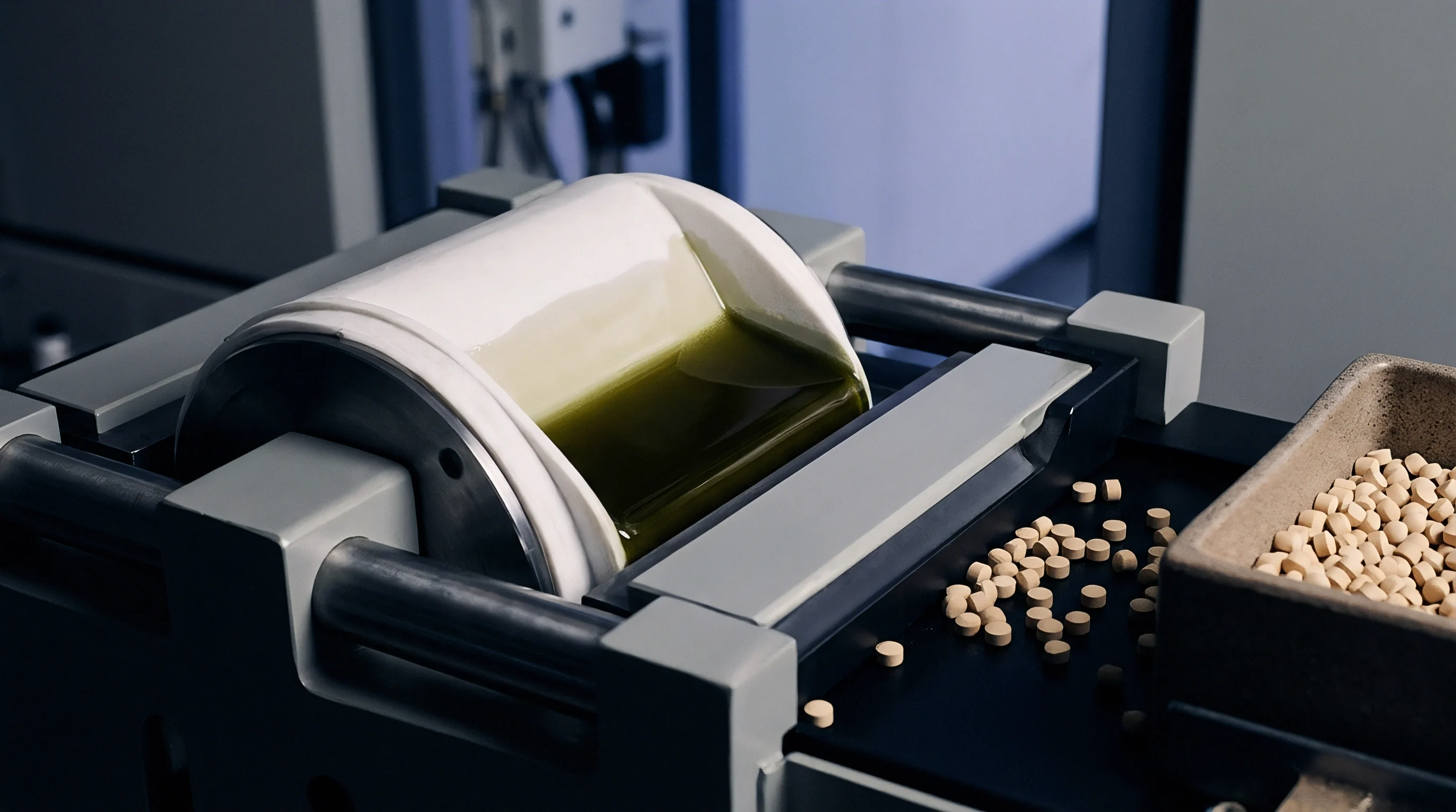
Carbonization Temperature Boundaries and Graphitization Resistance
Final heat treatment temperatures determine domain orientation and electrical conductivity in the hard carbon matrix. Below 900 degrees Celsius, the carbonized residue holds significant amounts of residual hydrogen and oxygen groups, leaving the material with low electrical conductivity and high voltage hysteresis during cycling. Raising the temperature to between 1000 and 1300 degrees Celsius drives off remaining heteroatoms, promotes aromatic ring condensation, and forms a network of turbostratic carbon crystallites.
In this range, short-range graphitic planes develop, though long-range three-dimensional order remains blocked by crosslinked defects and curved graphene edges.
| Temperature Range | Primary Reactions | Volatile Species | Interlayer Spacing d002 | Microstructural State |
|---|---|---|---|---|
| 200°C – 400°C | Hemicellulose/cellulose cleavage | H2O, CO2, levoglucosan | 0.420 nm | Amorphous biopolymer residue |
| 400°C – 700°C | Lignin aromatic condensation | CH4, tars, phenolic vapors | 0.390 – 0.410 nm | Defect-rich carbon framework |
| 700°C – 1000°C | Heteroatom elimination | H2, CO, trace light alkanes | 0.375 – 0.390 nm | Nascent turbostratic domains |
| 1000°C – 1300°C | Graphite domain consolidation | Trace H2 release | 0.360 – 0.375 nm | Closed-pore hard carbon matrix |
| 1300°C – 1600°C | Pore shrinkage & graphitization | None | Dense non-graphitizable carbon |
Soaking above 1400 degrees Celsius triggers pore collapse and overall structural shrinkage. At these temperatures, thermal energy gives carbon atoms enough mobility to heal defects and remove curvature, causing small closed pores to coalesce into dense graphitic ribbons. While electronic conductivity improves with higher soak temperatures, closed void volume drops significantly, cutting into the low-voltage plateau capacity essential for sodium storage.
Bio-derived hard carbons resist graphitization up to 1600 degrees Celsius because of the dense sp3-hybridized crosslinks and non-hexagonal ring defects locked into place during initial biopolymer condensation.
Whether ultra-high temperature soaking above 1500 degrees Celsius permanently seals closed pores or initiates irreversible graphitization domains remains unresolved across high-rate sodium anode literature.


Pore
Disordered carbons lack long-range crystalline symmetry, consisting of short, curved graphene sheets arranged in randomized turbostratic domains. These domains contain small stacks of parallel graphene layers separated by an average d002 interlayer distance larger than the 0.335 nanometers typical of natural graphite. In bio-derived hard carbons, this spacing ranges between 0.360 and 0.400 nanometers.
The expanded lattice accommodates larger charge-carrying ions like sodium, which cannot reversibly intercalate into standard graphite at room temperature. High-resolution X-ray diffraction measures d002 interlayer spacing across pilot production batches.

Where Does the Sodium Storage Plateau Originate?
Galvanostatic discharge curves for hard carbon anodes show two clear electrochemical regions during ion insertion. The sloping voltage region above 0.1 V versus Na/Na+ reflects ion adsorption on surface defects, heteroatoms, and exposed domain edges. The plateau below 0.1 V corresponds to ion insertion between expanding turbostratic interlayers along with filling inside closed micro-voids.
Small-angle X-ray scattering shows that closed pore volume directly determines capacity along this low-voltage plateau. Maximizing performance requires building up internal closed pore volume while minimizing exposed surface micropores that drive irreversible electrolyte decomposition.
Pore architecture splits into open pores accessible to liquid electrolyte and closed pores isolated within the carbon bulk. Nitrogen gas adsorption isotherms measure open surface area and pore distributions down to sub-nanometer scales, while carbon dioxide adsorption at 273 Kelvin probes ultra-fine micropores under 0.7 nanometers. Nitrogen cannot penetrate closed voids at 77 Kelvin during standard physisorption, so small-angle X-ray and neutron scattering quantify closed void volume, average pore radii, and scattering contrast.
Closed pores serve as internal reservoirs, accommodating metallic sodium clusters during deep discharge without driving extreme macro-scale strain across the electrode.
Shipments with BET surface area exceeding 15 square meters per gram trigger automatic batch rejection due to excessive first-cycle solid electrolyte interphase consumption.
Closed Porosity Formation and Interlayer Spacing Dynamics
Crosslinked precursor networks prevent graphene sheets from sliding into dense graphitic alignment during heat treatment. As volatile organic molecules escape, the spaces they leave behind become trapped between randomly oriented turbostratic domains, forming closed micro-voids bounded by single- or multi-layer graphene walls. The rigid carbon backbone prevents these voids from collapsing under external pressure during cooling.
Depending on the precursor and maximum carbonization temperature, closed void volume ranges from 0.05 to 0.25 cubic centimeters per gram. Structural defects like monovacancies, Stone-Wales defects, and non-hexagonal rings buckle individual sheets, preserving wider interplanar spacings throughout the bulk material.
- Washing raw biomass with deionized water removes surface dirt and soluble alkali metals before crushing.
- Acid digestion in 1.5 molar hydrochloric acid extracts insoluble silica and transition metal oxides at 80 degrees Celsius over four hours.
- Pre-carbonization heating to 450 degrees Celsius drives off low-molecular-weight volatiles and stabilizes polymer crosslinking.
- Pyrolysis at 1200 degrees Celsius forms closed micro-voids and establishes the target turbostratic domain spacing.
- Chemical vapor deposition with ethanol vapor at 900 degrees Celsius seals exposed surface micropores without reducing closed void volume.
Defect density directly affects electrical conductivity and the thermodynamics of ion insertion. Raman spectroscopy measures this structural disorder using the intensity ratio of the D-band (around 1350 cm-1) to the G-band (around 1580 cm-1). The D-band corresponds to lattice breathing modes in sp2 carbon rings near defects or edges, whereas the G-band reflects in-plane stretching of sp2 carbon pairs.
Hard carbons produce broad D and G bands with ID/IG intensity ratios between 1.0 and 1.4, indicating extensive structural disorder. Too much disorder degrades conductivity, increases initial voltage hysteresis, and triggers side reactions with the electrolyte. Controlled disorder, however, maintains electronic pathways while providing enough strain tolerance to prevent micro-cracking over long cycling.

Turbostratic Domain Mechanics under Mechanical Strain
Inserting charge-carrying ions between expanded graphene layers expands the lattice along its c-axis. While lithium intercalation in natural graphite causes a theoretical volume expansion of about ten percent, sodium insertion into hard carbon creates localized strain across individual, curved graphene stacks. Because these short-range crystallites are randomly oriented in three dimensions, local expansion vectors cancel out across the bulk particle.
As a result, bulk expansion in optimized hard carbon electrodes stays below five percent at full sodium capacity, distributing mechanical stress evenly and keeping the particle from fracturing during fast charge and discharge cycles.
Lattice strain from fast charging can degrade microstructure over extended operation. The techniques used to crosslink precursors mirror carbon fiber production, where mesophase pitch molecules are aligned under tension to produce graphitic ribbons of extreme tensile strength. For battery-grade hard carbon, the objective reverses: maximum structural disorder is needed to prevent directional expansion and stress concentrations.
Non-graphitizable carbons handle repeated strain cycles without undergoing order-disorder phase transitions. However, repeated sodium insertion into closed pores can form quasi-metallic sodium clusters; if the pores are too large, this plating becomes irreversible, yielding inactive metallic dendrites that shorten cycle life and risk internal short circuits. Microstructure mechanics determines mechanical durability under high current rates.
Higher crosslinking density in the starting biopolymer yields larger internal closed void volumes and lower open surface areas after final carbonization.


Intercalation
Ion transport in non-graphitizable carbons relies on a mix of surface adsorption and interlayer insertion. Storage begins along the sloping potential region as solvated ions shed their solvent shells at the electrode interface and bind to surface defects, vacancies, and functional groups. As the potential approaches zero Volts against the alkali metal reference, ions intercalate between expanded graphene sheets and fill internal closed voids.
The ratio between sloping and plateau capacity dictates the cell’s overall energy profile: sloping capacity enables fast rates at a lower average discharge voltage, while plateau capacity delivers high volumetric energy density at a flat, low working voltage.

Slope and Plateau Electrochemical Storage Mechanics
Sodium storage performance varies heavily with precursor selection, pyrolysis conditions, and surface treatments. Hard carbons made from sucrose versus coconut shell exhibit noticeably different voltage profiles based on their closed pore volumes and defect densities. Sucrose-derived carbons tend to form large closed pore volumes that yield high plateau capacity, ideal for energy-dense cell designs.
Coconut shell carbons deliver a better balance of rate capability and structural toughness, resisting particle cracking under fast charging. Higher heat treatment shifts capacity from the slope to the plateau by stripping away surface oxygen groups and consolidating graphitic interlayers. Hard carbon anodes exhibit a twelve percent capacity loss when cycled above two C rates.
| Precursor Base | Carbonization Temp | Initial ICE (%) | Total Capacity (mAh/g) | Plateau Fraction (%) | BET Surface Area (m²/g) |
|---|---|---|---|---|---|
| Coconut Shell | 1200°C | 84.2 | 310 | 58.0 | 4.2 |
| Hardwood Lignin | 1300°C | 81.5 | 335 | 64.5 | 6.8 |
| Sucrose Monomer | 1100°C | 78.0 | 350 | 71.0 | 12.5 |
| Rice Husk (Leached) | 1200°C | 76.4 | 290 | 49.0 | 18.1 |
| Corn Starch | 1250°C | 82.8 | 325 | 62.0 | 5.1 |
First-cycle irreversible capacity loss remains a major hurdle for commercial hard carbon anodes. Most of this initial sodium or lithium consumption goes into forming the solid electrolyte interphase (SEI). Below 1.0 V, liquid electrolyte solvents break down on exposed carbon surfaces, creating an electronically insulating but ionically conductive film of alkyl carbonates, sodium fluoride, and sodium carbonate.
Higher specific surface area directly increases the number of active ions trapped in this passivating layer during initial charging. Residual oxygen groups and surface defects drive ongoing electrolyte decomposition, raising cell impedance and degrading capacity over extended cycling. Applying a dense coating mitigates these parasitic losses.
Increasing the heating ramp rate expands open surface micropores at the direct expense of internal closed void storage capacity.
Volumetric Lattice Expansion and Strain Accumulation
Lattice expansion during cycling puts continuous mechanical stress on both the binder matrix and the current collector foil. As ions fit between graphene layers, d002 spacing expands reversibly by up to nine percent, depending on local ion concentration. While uniform materials expand evenly, disordered carbons experience localized shear strains at domain boundaries due to misaligned crystallites.
Over hundreds of deep cycles, these internal strains can cause micro-cracking inside the carbon particles, exposing fresh surface to the electrolyte, triggering secondary SEI growth, consuming electrolyte, and accelerating capacity decay.
- Interlayer Lattice Shear localized lattice mismatch between adjacent turbostratic crystallites during rapid ion insertion generates internal stress concentrations.
- Pore Plating Expansion over-accumulation of metallic sodium clusters inside closed voids creates internal volumetric hydraulic pressure against pore walls.
- Binder Matrix Decoupling macro-scale electrode swelling weakens polymeric binder bonds, isolating carbon particles from the conductive network.
- Exfoliation at Defects high current densities force localized ion accumulation along edge defects, driving localized graphene layer separation.
Electrode formulations must accommodate internal mechanical strains to preserve cell integrity. Standard slurries rely on carboxymethyl cellulose (CMC) and styrene-butadiene rubber (SBR) binders to maintain particle cohesion and adhesion to copper current collectors. Advanced formulations incorporate elastic polymer networks that absorb cyclic expansion without fracturing.
Active material loading must balance volumetric energy needs against electrolyte wetting rates: thick, dense coatings increase internal stress gradients during fast discharge, which can peel the active layer off the copper foil. Particle morphology and internal pore architecture must be designed together.
An unpassivated experimental batch expanding eight percent in thickness during fast charging can crush cell separator membranes and cause thermal shorts.


Refinement
Post-pyrolysis treatments alter surface chemistry and pore access to improve initial coulombic efficiency. As hard carbon leaves the high-temperature kiln, it typically retains exposed edge defects, open micropores, and surface ash. Chemical surface modifications seal these open pore entrances while leaving internal closed void volume intact.
Introducing liquid or gaseous hydrocarbon precursors at moderate temperatures cracks them on active surface sites, depositing a thin carbon film over micropore openings. Gas-phase chemical vapor deposition with ethanol, toluene, or methane between 700 and 900 degrees Celsius produces uniform surface coverage without penetrating deep into the internal closed voids.

Acid Leaching and Inorganic Ash Demineralization
Removing inorganic ash requires tailored acid digestion protocols based on the precursor’s mineral content. Silicates resist water washing and weak acids, demanding concentrated hydrofluoric acid or hot sodium hydroxide treatments. Hydrofluoric acid converts silicon dioxide into soluble fluorosilicic acid, which is rinsed out with deionized water, while iron, calcium, and magnesium oxides dissolve in warm hydrochloric acid washes.
Acid leaching alters surface chemistry by introducing hydroxyl and carboxyl groups; these must be thermally annealed under inert gas to passivate the material prior to slurry preparation. ICP-OES tracks residual ash levels after full mineral acid digestion.
- Hydrofluoric Acid Washing removes inert silicon dioxide networks that block ionic channels and add non-electroactive mass.
- Nitrogen Doping Passivation introduces pyridinic and pyrrolic surface sites that modify localized electronic conductivity and reduce active radical sites.
- Asphalt Pitch Coating seals open micropores through pyrolysis of thin hydrocarbon films, raising initial coulombic efficiency above eighty-five percent.
- Air Oxidation Etching creates controlled oxygen surface functional groups that expand low-voltage plateau capacity while increasing initial hysteresis.
When demineralization occurs dictates final pore morphology. Acid leaching raw biomass changes how biopolymers decompose during subsequent pyrolysis: removing catalytic alkali species before carbonization produces higher yields, fewer open micropores, and lower defect density. Leaching after pyrolysis, by contrast, dissolves mineral template particles embedded in the carbon matrix, leaving behind open mesopores and macropores that increase specific surface area.
Choosing between pre- and post-carbonization leaching depends on whether the design prioritizes high initial coulombic efficiency or fast electrolyte wetting for high-rate applications.
Residual sodium and potassium compounds in unwashed agricultural waste carbons accelerate electrolyte oxidation during elevated temperature storage.
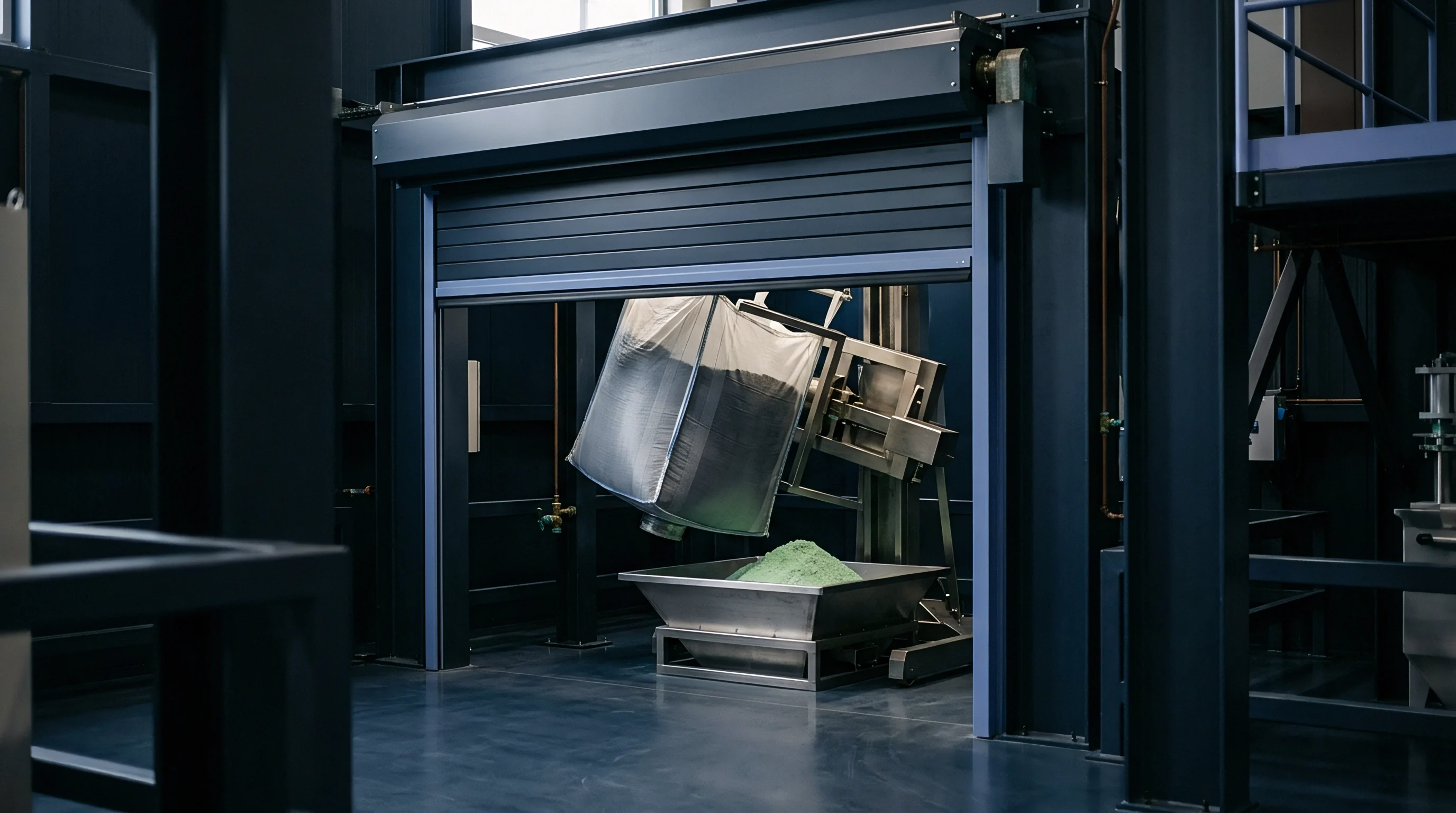
Surface Passivation and Chemical Vapor Deposition Coating
Surface passivation neutralizes active radical sites that drive ongoing electrolyte degradation. Coating hard carbon particles with asphalt pitch, coal tar pitch, or phenolic resin, followed by a secondary heat treatment at 1000 degrees Celsius, creates a smooth, low-surface-area shell. This coating fills open micro-voids and levels surface roughness, dropping specific surface area from over thirty square meters per gram to under three.
The resulting drop in surface area significantly reduces first-cycle capacity loss and improves electrode packing density during slurry coating operations.
| Treatment Method | Reagent Used | BET Surface Area Change | ICE Impact | Ash Content Residual |
|---|---|---|---|---|
| Pre-leaching | 1.0M HCl (80°C) | – 35% | + 5.2% | |
| Post-leaching | 2.0M HF / HCl | + 120% | – 8.4% | |
| Pitch Vapor Coating | Petroleum Pitch | – 85% | + 11.0% | Unchanged |
| CVD Gas Passivation | Ethanol (850°C) | – 75% | + 9.5% | Unchanged |
| Air Oxidation Etch | Air (350°C) | + 210% | – 14.2% | Unchanged |
Tight control of chemical vapor deposition parameters prevents heavy carbon deposits from blocking internal sodium transport pathways. Temperatures below 700 degrees Celsius cause incomplete hydrocarbon cracking, leaving sticky, low-molecular-weight tar films that impair electronic conductivity networks. Temperatures above 1000 degrees Celsius induce gas-phase nucleation, producing free soot particles that aggregate on surfaces and lower slurry packing density.
Optimal CVD conditions balance precursor flow rate, gas residence time, and temperature to form a uniform carbon shell two to five nanometers thick.
Contract clause 8.4 mandates that raw precursor batch ash content remain below zero point two percent by weight, shifting total demineralization liability directly onto the material vendor.

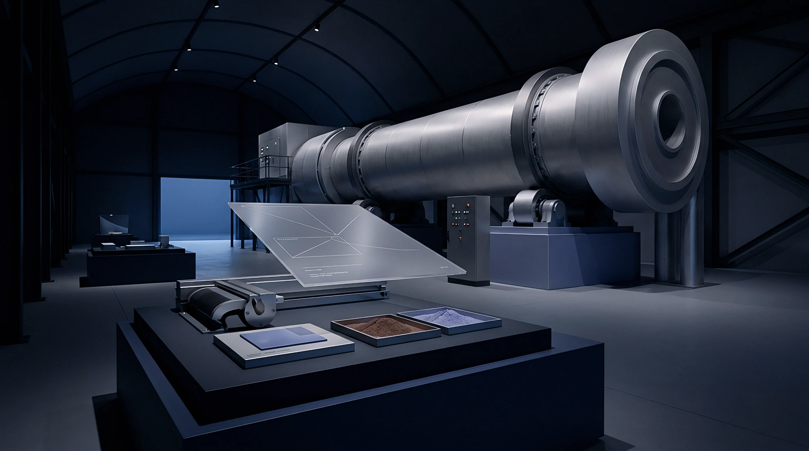
Economics
Material yield, energy consumption during high-temperature baking, and precursor purification drive the total cost per delivered cell cycle. Raw agricultural biomass looks cheap at the farm gate, but processing, bulk shipping, moisture extraction, and chemical treatment quickly compound landed costs. Coconut shell prices, for instance, fluctuate with seasonal harvests and competition from activated carbon water filter manufacturers.
Shipping uncompacted, wet biomass adds substantial freight surcharges per dry metric ton of usable precursor.

Precursor Carbon Yield and Mass Balance Arithmetic
Mass balance calculations illustrate actual commercial yields from bio-precursor carbonization. Starting with one metric ton of raw coconut shell at fifteen percent moisture leaves eight hundred and fifty kilograms of dry biomass. Pyrolysis at 500 degrees Celsius yields roughly thirty-five percent solid biochar ~ about two hundred and ninety-seven kilograms of intermediate carbon material.
Secondary high-temperature carbonization at 1200 degrees Celsius alongside CVD surface coating results in a final mass recovery of about twenty percent relative to the initial dry biomass. That leaves one hundred and seventy kilograms of battery-grade hard carbon anode powder per wet metric ton of raw feedstock.
Energy consumption during high-temperature carbonization represents the largest operating cost in synthesis. Running continuous, inert-atmosphere rotary kilns at 1200 to 1400 degrees Celsius requires massive electrical or natural gas inputs. Argon gas consumption adds a constant operating expense unless recovery systems are fitted to the exhaust.
Chemical waste treatment fees for hydrofluoric and hydrochloric acid leaching streams must also be factored in; skipping waste treatment or recovery planning can instantly wipe out profit margins on commercial lines. Kiln energy overhead scales with peak soak duration.
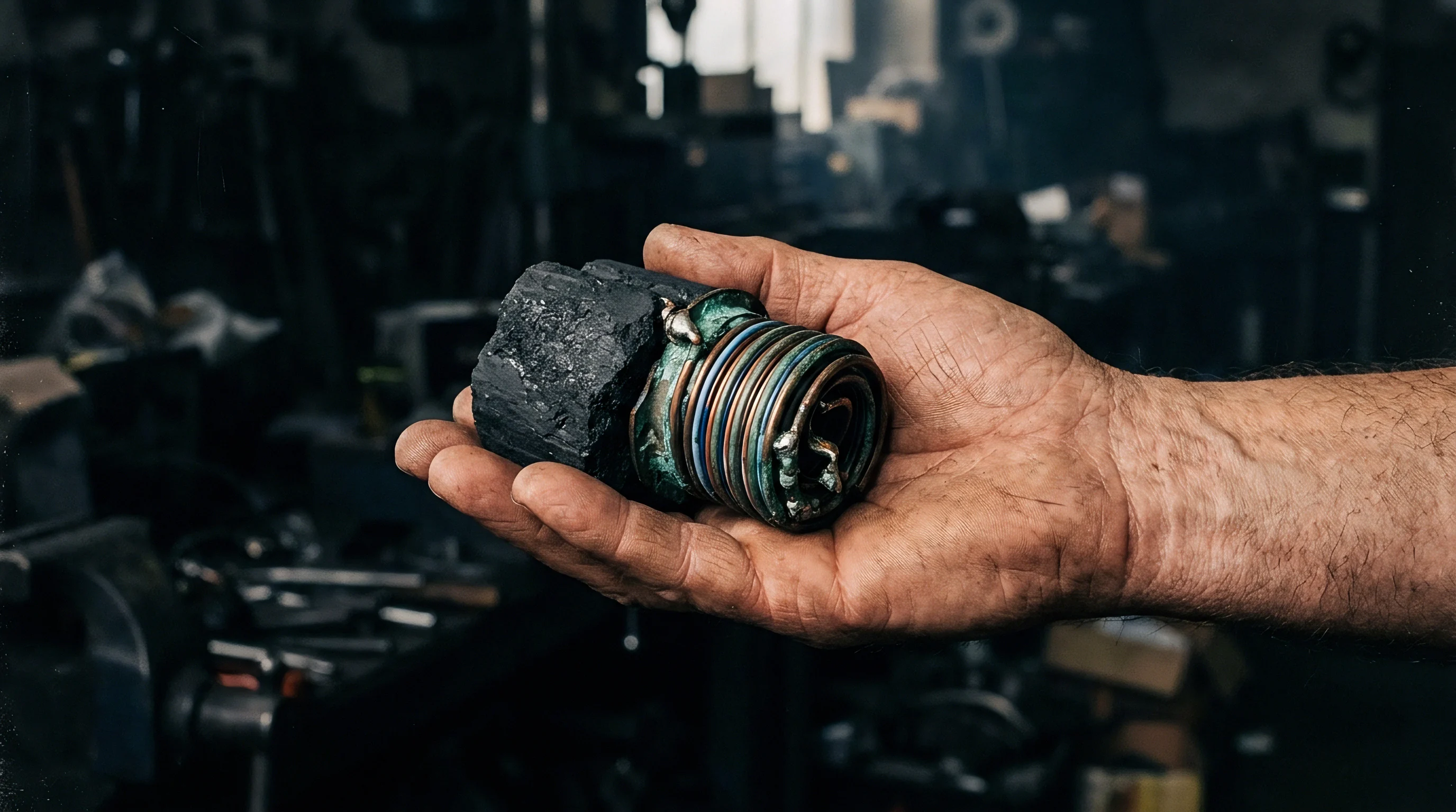
Commercial Specification Writing and Supply Chain Verification
Clear purchase specifications protect cell manufacturers from batch-to-batch variance and field failures. Datasheets need to state physical tolerances alongside explicit electrochemical test conditions: claiming 330 mAh/g is meaningless without defining the discharge rate, temperature window, voltage limits, and electrolyte formulation. Procurement contracts should require incoming batch testing for particle size distribution, BET surface area, tap density, residual ash, and initial coulombic efficiency.
Strict elemental purity limits are written into material supply contracts to protect cell cycle life.
Supplier verification requires multi-lot statistical process control data to confirm batch consistency. Because bio-precursors from agricultural supply chains show natural seasonal shifts in trace minerals and biopolymer ratios, procurement managers must require vendors to run blending programs that homogenize raw feedstocks prior to carbonization. Qualifying secondary suppliers protects production lines against localized crop failures, shipping bottlenecks, or sudden regulatory shifts in waste disposal at primary sites.
Calculations for landed cost incorporate raw biomass transport volumes, energy tariffs for continuous argon-purged kilns, chemical disposal fees for demineralization effluent, and real yields after final size classification.