Mechanical Fixture Baseline Verification Protocols for Metrology Channels
Fixture baseline verification protocols eliminate thermal and mechanical drift errors, securing cell swelling and dimensional metrology data accuracy.

Datum
Coordinate systems in automated battery test stations establish the spatial origin for all subsequent geometric and thermal measurements. When evaluating prismatic, pouch, or large-format cylindrical cells during formation or lifecycle degradation testing, the mechanical test fixture serves as the physical link between the device under test and the data acquisition channel. Dimensional sensors, LVDTs, tactile displacement probes, and thermistor contact plates rely entirely on the spatial integrity of the fixture reference faces.
If the mechanical baseline shifts from thermal gradients, mechanical yield, or wear at locator contact points, downstream channels record fixture deformation mixed in with true cell behavior. High-precision metrology requires that locator points constrain the cell in six degrees of freedom without creating localized stress points that skew electrochemical results.
Establishing a reliable mechanical reference framework requires strict kinematic alignment. In a standard 3-2-1 locating setup, three primary contact points define the reference plane, two secondary points align the longitudinal axis, and a final point fixes the transverse origin. For pouch cells that swell during lithium intercalation, contact surfaces must accommodate volume expansion without losing baseline alignment.
Nests are built on precision tooling plates machined from stress-relieved stock. Aluminum alloys such as 6061-T6 offer good thermal conductivity but expand significantly with heat. Invar and specialized ceramic plates resist dimensional growth at elevated temperatures, though they cost more and are harder to machine.
Fixture stability directly affects data quality. A backbone that deforms by twenty micrometers across a thermal soak cycle writes false expansion data into the metrology log. This artificial movement distorts the calculated breathing amplitude of active electrode stacks, leading to wrong conclusions about anode binder integrity or electrolyte wetting.
To prevent this, mechanical designs must decouple structural clamping frames from measurement reference planes. If clamping forces travel directly through metrology mounting points, strain on the outer frame flexes the sensor brackets and corrupts transducer readings.
| Cell Geometry | Datum Reference Type | Fixture Material | Thermal Drift Coefficient (µm/m/°K) | Allowed Datum Tolerance (mm) | Channel Error Contribution (%) |
|---|---|---|---|---|---|
| Prismatic Hard Case | 3-2-1 Kinematic Pin Nest | 316L Stainless Steel | 16.0 | ±0.012 | 1.8 |
| Large Pouch Stack | Flat Anodized Platen | 6061-T6 Aluminum | 23.0 | ±0.025 | 4.2 |
| Cylindrical 4680 | V-Block Centerline Stop | Invar 36 | 1.2 | ±0.005 | 0.4 |
| Ultra-Thin Pouch | Vacuum Sucker Array | MIC-6 Cast Aluminum | 23.6 | ±0.030 | 5.8 |
| Data collected at 25°C to 60°C ambient test sweep using calibrated laser displacement channels under zero external electrical load. | |||||

Physical Reference Alignment for Battery Cell Geometries
Positioning accuracy starts at the physical interface where the cell enclosure contacts the fixture pins. Prismatic cells with rigid aluminum cans index against stamped bottom chamfers or machined header shoulders. Because these features carry supplier manufacturing tolerances, fixture nests should use spring-loaded alignment shoes or flexure-based locators to avoid over-constraining the casing.
Over-constraining deforms the thin-walled housing, altering mechanical pressure across the internal jellyroll and causing non-uniform current density during high-rate discharge testing.
Pouch cells present a difficult datum challenge because of their flexible aluminum-laminate foil and variable seam widths. The critical baseline for thermal and swelling measurements is the active electrochemical area, not the perimeter heat seal. Tooling plates designed for pouch cells use recessed pockets that isolate the seam while supporting the active planar faces.
Ceramic gauge blocks with a thermal expansion coefficient under 0.1 ppm per Kelvin audit these pocket depths prior to mounting test samples. Optical displacement channels scan the pocket profile to verify that the bottom face stays flat within five micrometers across its total span.
At 45 degrees Celsius, an uncompensated 6061 aluminum fixture nest expands by 23.4 micrometers per 100 millimeters, exceeding the tolerance window of a pouch cell swelling test by 40 percent.
Cylindrical cells rely on centerline reference geometry set by dual V-blocks or precision-ground collets. Vertical tests use the bottom header shoulder as the primary Z-axis datum, whereas horizontal testing calls for self-centering jaws. Sensor mounting arms tied to these locators need high stiffness to resist mechanical vibration from cooling fans or automated loading gantries.
Resonance in these arms introduces high-frequency noise into displacement channels, masking subtle breathing events tied to phase transitions in silicon-graphite anodes.
Thermal Expansion Coefficients in Precision Tooling Nests
Temperature swings inside environmental chambers expand and contract every metal component in a metrology channel. When a test protocol ramps from minus twenty degrees Celsius up to sixty degrees Celsius, steel frames expand and shift the distance between a displacement sensor body and its target continuously. Unless the channel uses real-time mathematical thermal compensation or matched physical expansion, fixture growth gets misrecorded as cell swelling.
Material choice determines fixture baseline stability across changing thermal environments. Invar 36 exhibits minimal expansion near room temperature, which makes it well-suited for high-precision displacement channels. Cast aluminum plates like MIC-6 provide excellent flatness and stress relief, preventing warping over repeated thermal cycles, though their higher expansion rate requires active temperature monitoring.
Stainless steel resists corrosion from spilled electrolyte or condensation, but its lower thermal conductivity causes internal thermal gradients across the frame during rapid chamber ramps.
Unequal heating rates across a large frame create thermal bending moments that tilt sensor mounting axes relative to the cell surface, introducing cosine errors into displacement measurements. Correcting for this requires mapping sensor tilt across the working temperature range using multi-axis optical autocollimators during fixture commissioning.
Standard ISO 10360-2 requires that structural frame deflection remain under ten percent of the target measurement tolerance band ~ making uncalibrated frame bending a direct compliance issue under supply agreements.
Clamp
Applying uniform compression across active cell faces is necessary to mimic pack-level containment and capture true breathing metrics. Production EV modules use rigid endplates and compression straps to hold mechanical pressure on pouch and prismatic cells. This pressure suppresses electrode layer delamination, prevents lithium plating during fast charging, and extends cycle life.
Test fixtures must replicate these mechanical boundary conditions using controllable loading mechanisms while tracking force and displacement vectors.
Baseline test loads must balance firm mechanical restraint against sensor distortion. Pneumatic cylinders, hydraulic actuators, and servo-electric lead screws are common load sources. Pneumatic systems provide straightforward force control through pressure regulators, but air compressibility adds compliance that cushions rapid swelling impulses.
Servo-electric actuators paired with closed-loop load cells give precise position and force control, enabling constant-force or constant-volume test protocols at sub-newton resolution.
When a force transducer is mounted off-axis relative to the load vector, parasitic bending moments distort its output. Mechanical guide rods with linear ball bearings must maintain axial alignment to prevent stick-slip friction from corrupting force readings. When friction holds back part of the applied load, the inline load cell reports more force than the cell actually sees.
Designing a reliable compression interface requires mapping surface pressure distribution with pressure-indicating film or matrix sensor arrays. Local pressure spikes from surface unevenness or uneven fastener torque degrade active electrode materials. The baseline protocol should confirm that surface pressure stays uniform within ten percent across the active area before starting long-term electrical or swelling runs.
- Plate deflection distortion alters the pressure profile across the electrode bed, driving electrolyte toward low-pressure edges during formation.
- Transducer thermal zero shift causes parasitic voltage changes in strain gauge bridges when chamber temperatures shift during test sweeps.
- Hysteresis in guide pins traps frictional forces in mechanical slides, preventing small displacement shifts from reaching load cells.
- Pneumatic regulator fluctuation shifts line supply pressure over long runs, introducing low-frequency force drift into continuous channels.
- Platen non-parallelism concentrates clamping loads onto single cell edges, triggering premature mechanical short circuits.

Force Transducer Integration for Active Swelling Monitoring
Integrating strain gauge or piezoelectric load cells into the force loop requires isolating secondary force paths. These paths occur when structural springs, wiring harnesses, or cooling hoses bypass the load cell, routing part of the mechanical force around the sensor. Metrology channels tracking cell swelling should place inline load cells directly behind the moving platen, supported by spherical seats or flexible mounts to eliminate side loads.
Sensor selection dictates long-term stability under continuous compressive loads. Piezoresistive load cells offer high sensitivity and a compact footprint for tight chambers, but drift over test runs lasting months or years. Low-profile foil strain gauge transducers provide better long-term stability if their thermal compensation networks match the chamber environment.
Signal conditioning electronics for load channels require stable reference sources and high-resolution ADCs to resolve sub-micrometer thickness shifts.
Mechanical compliance within the force frame absorbs cell expansion energy, causing tactile transducers to report artificial thickness increases.
Calibrating force channels involves applying deadweight standards or using calibrated reference load cells across the working range. A static calibration at room temperature is not enough for channels operating across wide temperature swings. Dynamic thermal calibration protocols record sensor outputs at zero and full load across the full temperature range, generating custom compensation curves for each channel.

Pneumatic and Electric Actuation Repeatability Limits
Pneumatic actuators use proportional pressure valves to govern clamping forces. Minor shifts in supply pressure, valve temperature, or cylinder seal friction alter the load delivered to the cell face. Friction in standard lip seals creates a deadband where pressure adjustments fail to move the rod, producing step-like artifacts in swelling datasets.
Low-friction diaphragm cylinders or air bearings reduce this deadband, allowing continuous force control down to fractions of a bar.
Electric lead screw actuators avoid pressure supply fluctuations by converting motor rotation directly into linear displacement. Stepper or brushless motors fitted with high-resolution optical encoders provide precise positioning, establishing constant-volume conditions where swelling forces build against a rigid stop. Load cells embedded in the actuation stack record the force generated by the constrained cell, gathering data on peak internal swelling pressures over extended cycling.
Mechanical wear on lead screw threads or ball nuts degrades positioning repeatability over thousands of cycles. Routine baseline checks must monitor actuator backlash and axial play using bidirectional positioning audits with precision optical displacement channels. When measured backlash exceeds five micrometers, the actuation drive needs mechanical adjustment or rebuilding to stay compliant with baseline testing standards.
Incorrect force channel calibration mistakes true cell expansion for frame flex, leading integrators to accept cells that swell past physical module allowances and burst enclosure seals during thermal cycling.


Gauge
High-throughput test lines use contact probes, optical displacement sensors, and resistive strain gauges to track structural shifts under load. Choosing the right sensor means balancing resolution, range, response speed, and durability. Battery test chambers expose hardware to high temperatures, solvent vapors from off-gassing cells, and heavy electrical noise from high-current cyclers.
Measurement channels have to stay accurate and immune to these conditions.
Linear variable differential transformers (LVDTs) offer a durable option for tactile displacement tracking. These inductive sensors use a movable magnetic core passing through transformer windings to output a signal proportional to linear position. LVDTs have no wiping electrical contacts, giving them long operating life and high shock resistance.
Spring-loaded armatures maintain steady contact force on cell faces, provided the tip force stays low enough to avoid dimpling soft pouch laminate.
Because instrument manufacturers specify sensor accuracy under ideal laboratory conditions, published datasheets routinely omit bracket flex, frame spring rates, and thermal drift. A sensor rated for sub-micrometer resolution yields useless data if its mounting bracket sags under cooling fan airflow or flexes when actuators move. System baseline protocols must evaluate the assembled rig, verifying that physical stability matches raw sensor specs.
| Sensor Technology | Measurement Principle | Sub-Micrometer Resolution (µm) | Thermal Drift Rate (µm/°C) | EMC Noise Immunity | Calibration Interval (Days) |
|---|---|---|---|---|---|
| Spring LVDT | Inductive Mutual Impedance | 0.10 | 0.05 | High | 180 |
| Laser Triangulation | Optical Diode Array | 0.05 | 0.12 | Moderate | 90 |
| Capacitive Probe | Electric Field Gap | 0.01 | 0.02 | Low | 30 |
| Digital Contact Gage | Optical Glass Scale | 0.02 | 0.04 | High | 365 |

Can Optical Sensors Replace Tactile Probes?
Non-contact laser triangulation sensors eliminate probe force on soft pouch surfaces, but introduce sensitivity to surface reflectivity. These sensors project a laser spot onto the target and measure the angle of reflected light on a linear detector array. Surface variations on pouch foil, gloss shifts during thermal expansion, or printed text on cell casings can shift the light centroid and skew readings.
Applying diffuse target disks or anti-reflection coatings stabilizes optical channels, though it adds preparation steps.
Capacitive displacement probes deliver high resolution and fast response by measuring capacitance changes between the probe face and a conductive target. This method requires a stable dielectric medium in the gap. Shifts in humidity, air density, or venting solvent vapors alter the capacitive field and drift the reading.
Capacitive sensors need tightly controlled ambient environments or sealed enclosures to hold calibration.
Tactile digital contact gauges built with glass scales remain the reference standard for dimensional checks. These probes output direct quadrature signals, avoiding ADC drift and RF interference from high-current power cables. While more expensive, digital glass scales maintain absolute zero settings even through facility power outages.
Repeatability and Reproducibility Metrics across Multi Channel Scans
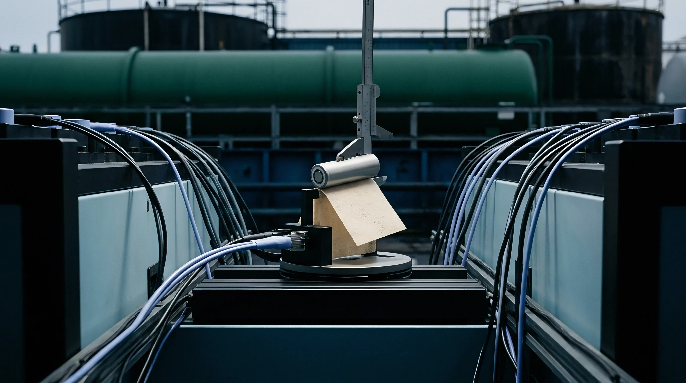
Establishing confidence in measurement channels requires full Gauge Repeatability and Reproducibility (GR&R) studies. Repeatability measures variance when one operator takes repeated readings on a stable standard using the same channel. Reproducibility quantifies variance across different operators, shifts, or test conditions.
A channel is considered capable only when total gauge R&R consumes under ten percent of the target product tolerance window.
Clause 7.4 of IEC 62660-1 dictates that dimensional metrology channels maintain an expanded measurement uncertainty below five micrometers across the full operating thermal envelope.
A valid gauge R&R study requires stable ceramic or metallic reference blocks rather than actual battery cells. Cells undergo continuous dimensional changes from state-of-charge shifts, thermal relaxation, and internal stress relief, making them unsuitable as static standards. On tier-one cell lines, baseline drift accounts for over 30 percent of false rejections.
Using live battery samples during gauge calibration confuses cell movement with instrument error, invalidating the statistical study.
Signal processing affects overall repeatability. High-frequency noise from battery cyclers must be filtered out digitally or in hardware without clipping real high-speed events like thermal runaway swelling or venting spikes. Filter cutoff frequencies should be documented in the channel specification to ensure data matches across facilities.
Baseline offsets frequently appear negligible in isolated bench checks, while cumulative drift across multi-channel signal conditioning hardware goes unaddressed.

Routine
Running systematic reference checks before every shift preserves data integrity across long qualification runs. Calibration routines should follow repeatable steps to verify sensor zero offsets, gain factors, alignment, and signal communication. Skipping pre-test zeroing allows unrecorded sensor drift or mechanical shifts to contaminate long-term cycling data.
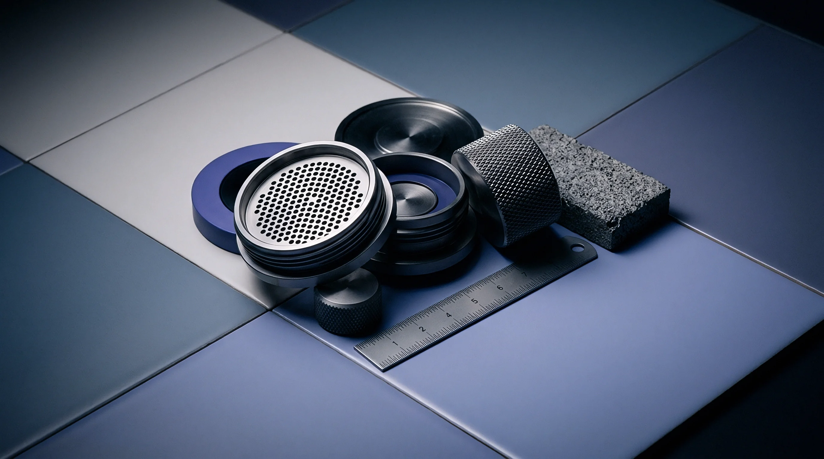
Establishing baseline confidence requires certified master reference artifacts with dimensions traceable to national standards. Precision ceramic or stabilized steel gauge blocks act as primary spatial references for displacement sensors. Thermal dummy cells equipped with internal temperature sensors verify heat transfer across liquid-cooled platens.
Force channels zero against certified weights or inline reference load cells backed by ISO 17025 certificates.
Automated baseline routines cycle actuators through full stroke ranges, checking for mechanical binding, friction signatures, and noise floor shifts. Station software limits raise warnings or trigger lockouts if sensor baselines drift beyond allowed bounds.
- Mount the zerodur master artifact in the primary nest using low-torque kinematic thumb screws.
- Energize sensor amplifiers thirty minutes before zero verification so signal conditioning boards reach thermal equilibrium.
- Drive the actuation gantry to the primary reference contact position at two millimeters per second.
- Record baseline voltage outputs from LVDT and load cell channels over a sixty-second window at one kilohertz sampling.
- Compare baseline averages against stored master block reference dimensions in the database.
- Apply automatic offset adjustments if baseline readings are within five micrometers of reference values, or trigger a hardware lockout if deviations exceed eight micrometers.

Master Standard Block Calibration and Zero Alignment
Zero alignment sets the geometric origin for displacement measurements. Master standard blocks shaped like target cell formats are loaded into the fixture before testing live cells. These blocks feature flat, parallel reference faces and zero electrical conductivity to prevent shorting sensor pins.
The clamping mechanism closes on the master block at standard force so sensors can record baseline zero offsets.
Thermal expansion differences between master blocks and fixtures require temperature tracking during zeroing. A master block stored at twenty degrees Celsius and loaded immediately into a fixture heated to forty-five degrees Celsius will expand rapidly and shift the zero point. Master artifacts must reach full thermal equilibrium inside the chamber before recording baseline values.
Three-point kinematic mounting on every metrology plate preserves positional repeatability during soak times.
Regular reference block verification separates physical cell deformation from instrument sensor drift.
Tracking baseline shifts over successive check cycles creates a predictive maintenance trail. A zero point that drifts steadily in one direction signals loose mounting hardware, lead screw wear, or failing sensor electronics. Catching these trends early lets maintenance fix mechanical issues before they spoil expensive cell test runs.

Thermal Drift Suppression in Metrology Channels
Thermal stability requires isolating sensitive metrology hardware from heat sources like power supplies, cycling switches, and chamber heaters. Glass-polyimide or ceramic composite insulation barriers placed between heated platens and sensor mounts prevent heat from conducting into displacement probes.
Differential measurement setups compensate for frame expansion. By placing a secondary reference displacement sensor on an unloaded reference post made of the same frame material, software subtracts frame expansion from the main measurement reading. This real-time differential subtraction cancels common-mode thermal drift across wide temperature sweeps.
Software drift compensation must run on raw, unfiltered signals rather than processed data to avoid mathematical aliasing and prevent uncalibrated channels from generating false failures. Audit logs should store both raw values and applied offset corrections to preserve data integrity for technical reviews or contractual disputes.
Temperature gradients across multi-channel fixtures degrade baseline accuracy unless reference frames incorporate thermal isolation breaks.


Dispute
Disagreements over incoming cell dimensions usually stem from mismatched metrology setups between cell factories and pack integration plants. When a supplier ships cells certified to tight thickness tolerances but incoming inspection logs them as out-of-spec, the discrepancy often lies in the test fixtures rather than the cells. Variations in fixture stiffness, clamping pressure, sensor tip force, or zeroing routines create systematic offsets between facilities.
Resolving these discrepancies requires cross-calibrating fixtures using identical master reference blocks and standardized procedures. Aligning test methods between buyer and supplier eliminates variations from ambient temperature, fixture flex, and sensor drift. Without aligned metrology baselines, claims over non-conforming batches spiral into legal disputes, delayed vehicle launches, and stranded inventory.
Decoupling clamping loads from sensing channels isolates measurement error. Clear contractual terms in supply agreements are needed to assign responsibility for fixture baseline accuracy. Quality contracts must explicitly specify mechanical datum features, clamp force profiles, thermal calibration ranges, and target gauge R&R scores for incoming inspection hardware.
Explicit engineering specs replace ambiguous quality claims with verifiable mechanical data.
| Calibration Schedule | Direct Calibration Cost per Channel ($) | Annual Downtime Hours per Rig | False Rejection Rate (%) | Risk-Adjusted Landed Cost Penalty ($/pack) |
|---|---|---|---|---|
| Per Shift (Automated) | 120 | 15 | 0.02 | 0.15 |
| Weekly (Manual) | 450 | 52 | 0.18 | 1.25 |
| Monthly (Manual) | 1,200 | 120 | 0.85 | 6.80 |
| Quarterly (Audit Only) | 2,500 | 200 | 3.40 | 24.50 |

Tolerance Stack Friction in Incoming Quality Audits
Tolerance stack-up calculations during pack design often assume rigid cell bodies and perfect measurement tools. Real battery cells have viscoelastic properties and deform under minimal force. If incoming inspection uses a tactile probe with two newtons of contact force while the supplier measured the same cell optically without contact, the tactile probe will compress the soft cell face and log a smaller thickness.
Discrepancies compound when incoming inspection measures cells at different states of charge or storage times. Fully charged cells are thicker due to lithiation swelling, while cells stored for weeks undergo mechanical relaxation that alters outer dimensions. Inspection protocols must specify state of charge, thermal soak times, and mechanical conditioning prior to dimensional audits.
When uncalibrated baselines cause test stations to log false dimensional failures, automated material handling routes conforming cell lots to quarantine, shutting down assembly lines and forcing unnecessary scrap reviews. Eliminating these bottlenecks requires matching fixture designs, sensor specifications, and calibration routines across the supply chain.

Contractual Allocation of Baseline Calibration Costs
Allocating the costs of maintaining metrology baselines requires clear boundaries between cell vendors, pack integrators, and test labs. Fixture calibration, master block certification, sensor replacement, and downtime represent real capital expenses. A structured quality agreement assigns these costs to the party responsible for managing each underlying mechanical variable.
Tooling wear shifts mechanical datums over time. Quality contracts should define maximum allowable datum wear and mandate recalibration intervals for locating nests. When a supplier requires custom fixtures to verify incoming lots, the contract must clarify whether buyer or seller pays for master reference artifacts and annual ISO 17025 calibration audits.
Investing in robust fixture frames, automated calibration hardware, and rigorous verification software provides the stable mechanical baseline needed to minimize commercial risk, protect supplier relationships, and ensure quality decisions rest on solid physical data.
Can automated baseline compensation algorithms bridge the gap between soft cell structures and rigid metrology channels without introducing secondary mathematical distortions into lifetime swelling logs?