NMC against LFP for Duty Cycles That Never Rest
LFP outperforms NMC in non-resting duty cycles by maintaining lattice stability, eliminating continuous microcracking, and cutting cooling costs over 4,000 cycles.


Swell
Running continuous current through lithium-ion cells maintains constant mechanical strain across the electrode stacks. Without the voltage and thermal relaxation built into normal rest intervals, internal stress dynamics change entirely. Standard industrial setups allow batteries to rest between charge and discharge cycles, giving concentration gradients time to clear, temperatures room to equalize, and crystal lattices a chance to recover.
Under continuous fast charging and high-rate discharging, however, the cell remains under constant physical and thermal stress, exposing sharp mechanical differences between Nickel Manganese Cobalt (NMC) and Lithium Iron Phosphate (LFP) chemistries.
The core physical distinction comes down to crystallographic deformation as lithium leaves and re-enters the cathode. High-nickel layered oxides like NMC622 and NMC811 suffer pronounced anisotropic volume changes during cycling. As lithium extracts on charge, unit cell dimensions shrink unevenly along the c-axis and a-axis.
Reversing immediately into discharge forces rapid lithium re-insertion and abrupt lattice expansion. Done continuously, this cycle builds intense internal shear stress inside individual secondary spherical particles, eventually producing microcracks along grain boundaries that expose fresh cathode surfaces to liquid electrolyte.
LFP cathode materials react quite differently under load. Lithium iron phosphate relies on a three-dimensional olivine structure tied together by strong covalent phosphorus-oxygen bonds. During delithiation, it transforms into heterosite (FePO4) via a two-phase reaction.
Unit cell volume shifts by roughly 6.8 percent between fully lithiated LiFePO4 and delithiated FePO4, but the rigid olivine framework holds its shape without anisotropic shear. Those sturdy P-O bonds prevent microcracking during rapid ion transport, sparing LFP from the cumulative intergranular fracturing that degrades high-nickel NMC.
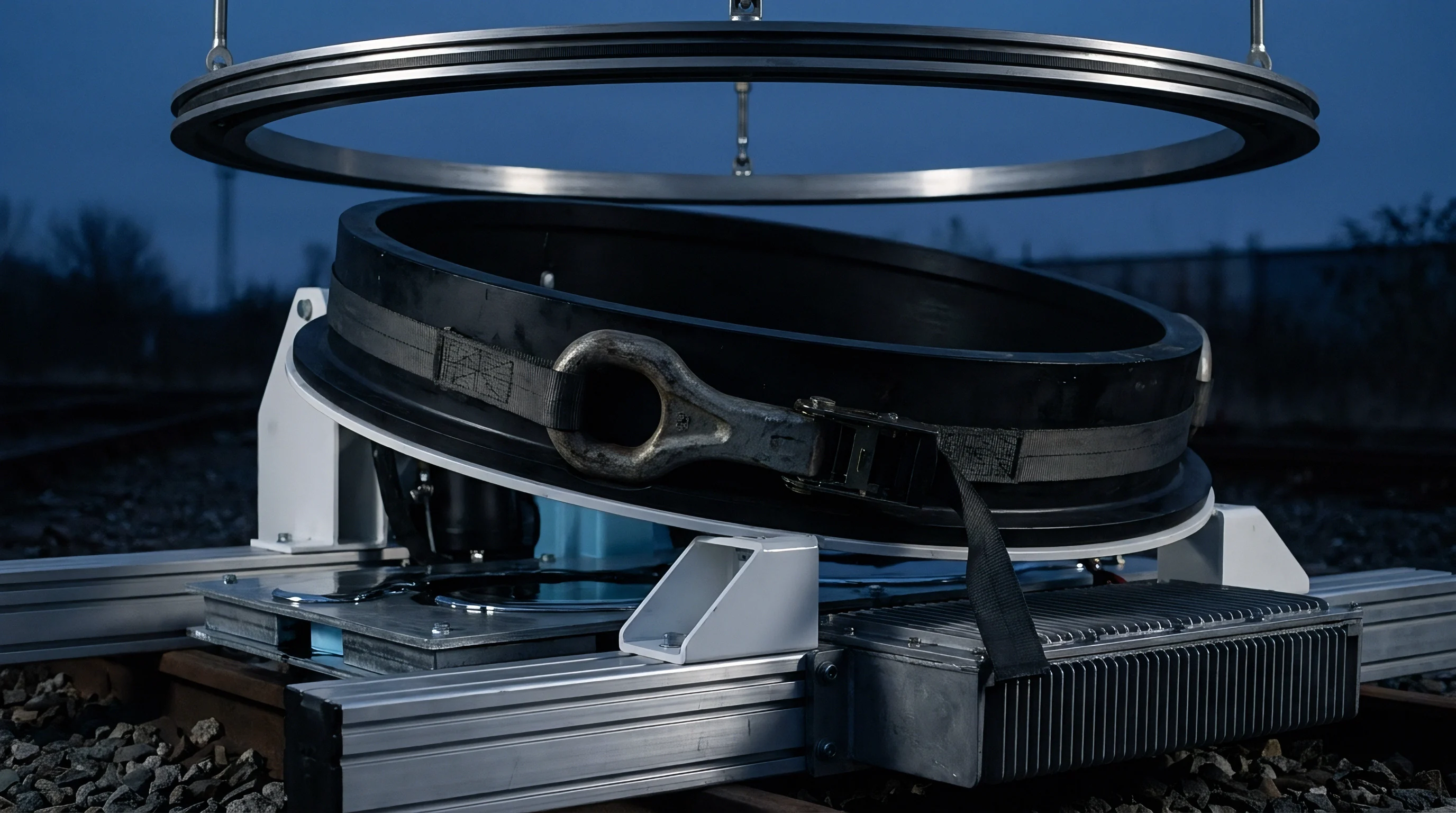
Lattice Phase Changes under Continuous Duty
Nickel-rich layered oxides contract unevenly during deep delithiation. In NMC811 (LiNi0.8Mn0.1Co0.1O2), stripping lithium past 75 percent state of charge forces a shift from the hexagonal H2 phase to the hexagonal H3 phase. That transition contracts the c-axis lattice parameter by nearly 3 percent across a narrow state of charge window.
Driving a cell through this phase boundary repeatedly at high current density without relaxation accelerates mechanical fatigue throughout the particle bulk.
On a macro scale, this lattice shift shows up as physical cell swelling. Pouch and prismatic NMC cells expand and contract with every cycle, pulsing thousands of times a year in heavy industrial service. Over time, that constant motion deforms separators locally, distorts pressure distributions across electrode faces, and severs electrical contact between active particles, conductive carbon, and current collectors.
Once active material isolates from the conductive network, internal impedance climbs, raising local Joule heating and speeding up cell degradation.
LFP cells move through a straightforward two-phase transition between LiFePO4 and FePO4 without entering unstable high-voltage states. The olivine structure remains stable across the full state of charge window from 0 percent to 100 percent. Operating at lower cell voltages (typically 2.5 V to 3.65 V compared to 3.0 V to 4.2 V or 4.35 V for NMC), LFP places significantly less oxidative stress on organic carbonate electrolytes at the cathode surface.
Reduced oxidation minimizes gas generation from electrolyte breakdown, keeping pouch swelling and pack deformation low over continuous service lives.
Sustained compressive clamping delays cathode microcracking by preventing intergranular pore widening during relentless lithium intercalation.

Cathode Particle Microcracking Dynamics
Mechanical fatigue builds quickly inside particles undergoing unbroken state-of-charge swings. In high-nickel NMC, microcracks originate along primary grain boundaries within the spherical secondary particles. Capillary action and pressure swings draw liquid electrolyte deep into these fissures during cycling.
Once inside the particle core, the electrolyte forms secondary SEI layers deep within the cathode structure, consuming active lithium ions and causing permanent capacity loss.
At higher temperatures, reactions between the electrolyte and freshly exposed NMC surfaces release lattice oxygen. Transition metals ~ particularly nickel and manganese ~ dissolve into acidic electrolyte generated by trace moisture and fluorine species, then cross the porous polymer separator to the graphite anode. Once deposited, these metals poison the protective anode SEI, triggering steady lithium consumption and self-discharge.
Without rest periods, this degradation loop operates continuously, steadily reducing capacity while increasing cell impedance.
LFP particles maintain structural integrity because the olivine lattice lacks the vulnerable grain boundaries characteristic of synthesized polycrystalline NMC spheres. Commercial LFP typically consists of single-crystal nanoparticles or micro-assemblies coated in a uniform carbon layer. This carbon shell improves electrical conductivity while shielding the iron phosphate crystal surface from the electrolyte.
Even under high continuous C-rates, carbon-coated LFP resists mechanical breakdown, avoiding transition metal dissolution and keeping the anode SEI stable across multi-year deployments.

Mechanical Confinement and Module Clamping Pressure
Prismatic aluminum casings tolerate internal gas pressure up to their yield points, but physical expansion of the electrode stack pushes constantly against the enclosure walls. Managing cell swelling during uninterrupted industrial operation requires rigid module clamping with steel end-plates and tension straps. The initial preload pressure applied during pack assembly largely determines long-term mechanical survival under continuous cycling.
NMC cells require narrow initial clamping tolerances, typically between 0.3 MPa and 0.8 MPa. Under-clamping permits anisotropic expansion to open intergranular gaps, speeding up particle isolation and capacity loss. Over-clamping causes swelling at full charge to compress the separator past its elastic limit, closing pore volume, increasing ionic diffusion resistance, and raising the risk of puncture shorts.
During continuous cycling, thermal expansion compounds mechanical swelling, often driving peak module pressure above 2.0 MPa.
LFP cells exhibit modest, predictable dimensional changes driven primarily by thermal expansion and the small volume difference between LiFePO4 and FePO4. A static clamping pressure between 0.5 MPa and 1.0 MPa remains effective across thousands of continuous cycles. LFP avoids late-life pressure spikes because gas generation remains minimal at normal operating temperatures.
This mechanical stability simplifies module frame designs by eliminating the spring-loaded compliance mechanisms required to absorb heavy NMC expansion.
| Parameter | NMC811 (Pouch / Prismatic) | NMC622 (Prismatic) | LFP (Prismatic Industrial) |
|---|---|---|---|
| Crystal Structure System | Layered Hexagonal (R3-m) | Layered Hexagonal (R3-m) | Orthorhombic Olivine (Pnma) |
| Unit Cell Volume Variance (0-100% SOC) | 5.2% to 7.8% (Anisotropic) | 3.5% to 4.8% (Anisotropic) | 6.8% (Isotropic / Two-Phase) |
| Cathode Microcracking Susceptibility | Severe after 800 Unrested Cycles | Moderate after 1,500 Cycles | Negligible over 4,000+ Cycles |
| Peak Module Swelling Force Growth | 150% to 300% of Initial Preload | 80% to 150% of Initial Preload | 15% to 30% of Initial Preload |
| Optimal Assembly Clamping Preload | 0.3 to 0.5 MPa | 0.4 to 0.6 MPa | 0.5 to 1.0 MPa |
| Gas Generation Rate at 45°C Continuous | High (CO2, CO, Alkane species) | Moderate (CO2, Hydrocarbons) | Very Low (Trace Hydrocarbons) |
Cell expansion under continuous cycling determines initial mechanical clamping preload specs. In heavy industrial equipment like automated guided vehicles and warehouse robotics, module space is tight, forcing frame designs to accommodate physical swelling over the operational lifetime. An NMC module requires up to 8 percent volumetric clearance inside its steel frame to prevent cell crushing.
By contrast, LFP requires under 2 percent volumetric margin, delivering superior system-level packing efficiency despite its lower cell-level energy density.
Sustained mechanical stress degrades internal electrode alignment over time. Repeated expansion and contraction distort the stack, leading to jellyroll buckling or telescoping. In pouch cells under continuous high-temperature duty, uneven surface pressure creates localized current density hotspots that trigger lithium plating during fast charging.
Plated metallic dendrites can pierce the separator, introducing risks of micro-shorts, self-discharge, and thermal runaway. LFP cells maintain uniform pressure distribution under clamping, resisting localized stress concentration and internal stack distortion.
Published cycle-life ratings assume standard 30-minute thermal relaxation intervals between charge and discharge phases.


Arithmetic
Electrochemical degradation under continuous operating schedules departs sharply from standard laboratory test curves. Qualification protocols such as IEC 62619 or UL 1973 include multi-hour rest periods after full charge and discharge states. Those pauses bring core temperatures back to ambient baselines, let concentration gradients in the electrolyte and solid matrix equalize, and limit total exposure to elevated thermal and electrical stress.
When a duty cycle eliminates these relaxation windows, operating continuously in a non-equilibrium state fundamentally alters the kinetics governing capacity fade and impedance growth.
Accurate continuous-duty modeling requires decoupling calendar aging from active cycle aging while accounting for sustained internal self-heating. In intermittent service, total capacity loss equals calendar degradation (an Arrhenius fit based on static SOC and temperature) plus cycling degradation (throughput and depth of discharge). In an unrested cycle, continuous current keeps core temperatures 10°C to 25°C above ambient.
Because kinetic rate constants for parasitic side reactions remain elevated around the clock, calendar aging occurs at the elevated baseline produced by internal Joule heating rather than room temperature.
Joule heating losses scale quadratically with current density (P = I² R_internal). As internal resistance (R_internal) grows from SEI accumulation and electrode degradation, heat generation accelerates over the life of the cell. In continuous applications, this creates a thermal feedback loop: higher resistance generates more heat, elevated temperatures speed up SEI growth and electrolyte oxidation, and thicker SEI increases resistance further.
Without rest periods to interrupt this cycle, NMC chemistries hit non-linear capacity roll-off much earlier than standard datasheets suggest.
Thermal Equilibrium in Unbroken Cycling
Without rest periods for passive heat dissipation, internal resistance generates thermal energy continuously. Heat generation in a cell during continuous cycling combines ohmic losses, entropic heat, and mass transfer polarization. The thermal energy balance equation is expressed as:
Q_generated = I (V_ocv – V_cell) + I T (dV_ocv / dT)
Here, I represents operating current, V_ocv is open-circuit voltage, V_cell is cell operating voltage, T is absolute temperature, and (dV_ocv / dT) is the entropic heat coefficient. For NMC, this coefficient changes sign across state-of-charge ranges, creating alternating endothermic and exothermic zones during cycling. For LFP, the entropic coefficient remains near zero across most of the operating window (10 percent to 90 percent SOC), meaning heat generation stems almost entirely from ohmic and polarization resistance.
Under continuous operation, the cell reaches a thermal steady state where heat generated balances heat dissipated to the cooling system. The thermal equilibrium equation is defined as:
Q_generated = h A (T_core – T_coolant) + k (dT / dx)
where h is the heat transfer coefficient, A is cell surface area, k is thermal conductivity, and T_core is cell center temperature. Because NMC materials have relatively low cross-plane thermal conductivity (roughly 0.5 to 0.7 W/m·K) compared to current collectors and LFP layers, substantial thermal gradients develop between the core and casing. A core-to-case delta of 12°C is common in large 280Ah NMC prismatic cells during continuous 1C cycling.
That gradient skews current distribution across electrode sheets, causing the hotter core to degrade faster than the cooler exterior and driving localized capacity loss.

Coulombic Efficiency and Kinetic Fade
Parasitic side reactions consume active lithium during every charge transfer. Coulombic Efficiency (CE) measures the ratio of discharge capacity to charge capacity per cycle. In a perfectly reversible cell, CE would equal 1.00000.
Commercial lithium-ion cells fall just short of this baseline ~ typically 0.9992 to 0.9999 ~ due to ongoing SEI growth, electrolyte oxidation, and metal-catalyzed reactions.
The compound effect of Coulombic Efficiency on long-term capacity retention is severe under continuous duty. If a cell operates at a constant CE of 0.9995 without rest, capacity retention after N cycles follows the geometric series:
Capacity_Retention = (CE)^N
At N = 2,000 cycles, a CE of 0.9995 yields retention of (0.9995)^2000 = 0.367, or 36.7 percent of initial capacity. To reach 4,000 cycles while retaining 80 percent capacity (0.80 retention), average Coulombic Efficiency must hit:
CE = (0.80)^(1/4000) = 0.999944
LFP chemistries maintain higher Coulombic Efficiencies (0.99990 to 0.99997) at elevated temperatures than NMC (0.99920 to 0.99980). The lower operating voltage of LFP minimizes electrolyte oxidation at the cathode, keeping parasitic currents low. High-nickel NMC cathodes running at continuous potentials above 4.1 V suffer steady electrolyte oxidation, resulting in lower Coulombic Efficiency and faster depletion of cyclable lithium.
- Calculate daily full equivalent cycle throughput based on system operational hours and average charge and discharge power profiles.
- Establish continuous steady-state core cell operating temperatures using combined thermal-electrochemical modeling under maximum ambient environment conditions.
- Apply temperature-dependent kinetic decay rate modifiers to base degradation curves for both calendar and cycling loss equations.
- Determine internal impedance growth curves to project escalating Joule heating losses over the target operational lifespan.
- Verify minimum acceptable end-of-life capacity thresholds against system minimum power and runtime requirements to set target pack replacement intervals.

Capacity Retention Modeling under Continuous Loads
Predictive degradation models rely heavily on continuous thermal equilibrium once rest intervals vanish. Standard empirical fits express loss of lithium inventory (LLI) and loss of active material (LAM) as power-law functions of equivalent full cycles (EFC) and time (t):
Q_loss = A (EFC)^z exp(-E_a / (R T)) + B t^m exp(-E_a / (R T))
In this formulation, A and B are pre-exponential rate constants, z is the cycling power exponent (typically 0.5 to 0.8), m is the calendar time exponent (~0.5 for diffusion-controlled SEI growth), E_a is activation energy, R is the gas constant, and T is absolute temperature. In continuous duty, time (t) and equivalent full cycles (EFC) scale together by a constant factor. At continuous 1C charge and 1C discharge, one EFC runs every 2 hours, accumulating 12 EFC per day or 4,380 EFC per year.
In continuous 1C cycling tests at 45°C without rest intervals, NMC811 pouch cells lose 24 percent capacity after 1,100 cycles, compared to a 3 percent drop in LFP prismatic cells. Rapid NMC fade under high temperatures stems from accelerated metal dissolution and secondary SEI growth on microcracked cathode particles. The empirical cycling exponent z for NMC climbs from 0.55 under rested, room-temperature conditions to over 0.85 during continuous 45°C unrested operation ~ reflecting a shift from simple diffusion-controlled degradation to severe reaction-driven material breakdown.
LFP maintains an empirical exponent z near 0.50 even during continuous 45°C cycling. The linear scaling of capacity loss against the square root of equivalent full cycles confirms that LFP degradation remains bounded by predictable SEI growth at the anode. Sudden non-linear capacity drop-offs (“knee points”) do not appear in LFP until retention drops below 60 percent SOC, whereas NMC cells frequently hit sharp capacity knees between 75 percent and 80 percent retention under continuous high-rate cycling.
| Operating Condition | NMC811 (1C Continuous) | NMC622 (1C Continuous) | LFP (1C Continuous) |
|---|---|---|---|
| Steady-State Delta T (Air Cooled) | +18°C above Ambient | +14°C above Ambient | +8°C above Ambient |
| Average Coulombic Efficiency (40°C) | 0.99945 | 0.99965 | 0.99995 |
| Cycles to 80% Capacity (25°C Ambient) | 1,200 Cycles | 2,200 Cycles | 6,000 Cycles |
| Cycles to 80% Capacity (40°C Ambient) | 650 Cycles | 1,100 Cycles | 4,500 Cycles |
| Impedance Growth (1,000 Cycles @ 40°C) | +140% R_internal | +75% R_internal | +18% R_internal |
| Knee-Point Onset Retention | 78% SOH | 74% SOH | < 60% SOH |
Capacity retention models must also account for state-of-charge operating windows. Cycling NMC within a restricted band, such as 20 percent to 80 percent SOC, reduces c-axis lattice strain and extends cycle life by 200 to 300 percent. However, capping SOC reduces usable energy by 40 percent, dropping effective pack-level energy density to 110-130 Wh/kg.
LFP operates across a broad 5 percent to 95 percent SOC window under continuous cycling with negligible structural penalty, delivering 120-140 Wh/kg at the pack level. The nominal energy density advantage of NMC disappears when restricted operating windows are required for long-term survival.
Self-heating during continuous fast charging introduces additional modeling complexity. Charging at 1.5C to 2C generates intense localized heat at anode tab connections, where lithium transport through the electrolyte must match current density to prevent anode over-polarization. Under continuous operation with elevated internal resistance, anode potential can fall below 0 V vs.
Li/Li+ during high-rate charge phases. When this occurs, metallic lithium plates onto the graphite surface rather than intercalating into the carbon lattice. This plated lithium forms mossy or dendritic structures that react aggressively with electrolyte solvents, leading to irreversible capacity loss and serious safety risks.
Temperature strongly influences active material degradation. Thermal management systems for non-resting duty must maintain core temperatures below 35°C to prevent accelerated fade. For NMC, each 10°C rise in continuous operating temperature doubles transition metal dissolution rates.
For LFP, a 10°C rise modestly increases parabolic SEI growth without triggering phase changes or structural lattice breakdown. LFP remains chemically stable at continuous internal temperatures up to 55°C, making it significantly more resilient in warm industrial environments with limited auxiliary cooling power.
Continuous 1C charge and 1C discharge cycling at 45°C without thermal relaxation reduces NMC811 discharge capacity to 76 percent after 1,400 cycles, whereas LFP retains 91 percent capacity under identical continuous load.
Temperature control during continuous charge transfer dictates total lifetime energy throughput far more than nameplate capacity.

Audit
Batch verification for continuous industrial duty requires far tighter screening than standard vendor datasheets provide. Factory grading relies on 25°C baseline testing with generous rest intervals between charge and discharge phases. Those factory metrics obscure micro-defects, impedance variations, and tab misalignments that remain benign during light cycling but prove catastrophic under continuous duty.
Selecting cells for non-resting applications requires incoming audit protocols specifically tailored to sustained thermal and mechanical stress.
Incoming audits for continuous duty begin with strict sorting based on initial internal resistance (AC-IR and DC-IR). Standard commercial lots sort cells into Class A, B, and C based on capacity windows of ±2 percent and AC-IR spreads of ±5 percent. For continuous applications, standard Class A tolerances are far too broad.
A cell with an initial DC-IR 5 percent higher than its series neighbors generates 10 percent more Joule heat at 1C. Over months of 24/7 operation, that single high-impedance cell operates at higher temperatures, degrades faster, and reduces the usable capacity of the entire series string.
Factory audits must also verify slurry coating uniformity and edge slitting quality on the production line. Edge burrs on slitted foils or slight variations in slurry thickness concentrate local electric field intensity. Under continuous high current, these field spikes trigger localized lithium plating during fast charging.
Auditing requires tearing down random samples from incoming lots, extracting jellyrolls or plates, and inspecting foil edges under scanning electron microscopy (SEM) to ensure burrs remain under 5 micrometers.
Which Electrochemical Mechanism Limits Continuous High Temperature Operation?
Electrolyte breakdown at the solid-electrolyte interface accelerates once continuous operating temperatures exceed 40°C. In NMC cells at sustained elevated temperatures, capacity loss is dominated by the ongoing consumption of active lithium inventory through SEI breakdown and reformation. Above 40°C, the primary organic SEI component ~ lithium ethylene dicarbonate (LEDC) ~ decomposes into inorganic lithium carbonate (Li2CO3) and lithium fluoride (LiF). This reaction releases carbon dioxide, increasing internal cell pressure while depleting cyclable lithium.
In LFP cells, high-temperature degradation is limited by slow iron dissolution and subsequent migration to the anode. Although LFP is significantly more stable than NMC, trace hydrofluoric acid (HF) formed by moisture reacting with LiPF6 salt gradually leaches iron from the olivine structure at elevated temperatures. Dissolved Fe2+ ions diffuse across the separator and deposit on the graphite anode, destabilizing the SEI layer.
Nevertheless, iron leaching kinetics in LFP progress roughly two orders of magnitude slower than nickel and manganese dissolution in NMC at equivalent temperatures.
Electrolyte formulation is critical to controlling thermal breakdown. Continuous-duty cells require stabilizing additives such as vinylene carbonate (VC), fluoroethylene carbonate (FEC), or propane sultone (PS) to form resilient, inorganic-rich SEI films on both electrodes. Quality audits must verify chemical formulations to confirm these high-temperature additives are present, particularly when specifying NMC cells for continuous operation.

Differential Voltage Analysis on Unrested Cells
Incremental capacity curves derived from cycling data help isolate specific degradation mechanisms within active materials. Differential Voltage Analysis (DVA, dV/dQ vs. capacity) and Incremental Capacity Analysis (ICA, dQ/dV vs. voltage) convert subtle slope changes in charge and discharge profiles into distinct peaks corresponding to electrochemical phase transitions.
Monitoring shifts in peak position and height across continuous cycling identifies active degradation mechanisms without destructive tear-downs. In NMC, unbroken cycling shifts cathode phase transition peaks toward higher voltages during charge and lower voltages during discharge, reflecting rising charge transfer resistance. Concurrently, diminishing peak areas signal irreversible active material loss caused by microcracking and surface conversion into inactive rock-salt (NiO-like) phases.
LFP displays distinct ICA signatures characterized by sharp, narrow peaks tied to its flat two-phase insertion plateau between 3.25 V and 3.40 V. Under continuous cycling, LFP peak positions show minimal drift, confirming stable charge transfer resistance. Peak area contracts gradually, reflecting pure loss of cyclable lithium without damage to the iron phosphate crystal framework. Quality audits rely on ICA tracking to detect anomalous fade rates during 50-cycle qualification runs.
Compliance with IEC 62619 section 7.2 thermal abuse testing obligates integrators operating without rest cycles to maintain continuous cell-to-cell temperature variations under three degrees Celsius.

Screening for Latent Defects in Incoming Cell Lots
Acoustic imaging and electrochemical impedance spectroscopy reveal internal structural defects prior to pack assembly. Incoming quality control for continuous-duty cells requires dynamic screening rather than basic open-circuit voltage measurements. Electrochemical Impedance Spectroscopy (EIS) measures complex cell impedance across 10 kHz to 10 mHz, separating total internal resistance into discrete physical components.
On an EIS Nyquist plot, the high-frequency intercept indicates pure ohmic resistance (R_ohmic) ~ encompassing collector foils, tab welds, and electrolyte conductivity. The mid-frequency arc reflects solid-electrolyte interphase resistance (R_sei) and charge transfer resistance (R_ct) at electrode interfaces. The low-frequency tail represents Warburg impedance (W), tracking solid-state lithium diffusion within active particles.
Cell lots intended for continuous duty require tight statistical distributions for R_ct and R_sei. Lots exhibiting broad distributions for charge transfer resistance should be rejected, as high R_ct cells generate excessive local heat under continuous current and fail prematurely in series strings.
Evaluating batch-level differential voltage curves verifies chemical consistency prior to committing to multi-megawatt volume orders. Ultrasonic inspection measures the velocity and attenuation of acoustic waves passing through sealed prismatic cells. Layer delamination, dry electrolyte pockets, or internal gas bubbles attenuate the acoustic signal sharply, generating clear visual maps of internal structural flaws.
Identifying dry spots during incoming audits prevents cells prone to localized overheating from entering continuous service.
Cell Audit Requirements for Continuous Duty Deployment ~
- AC-IR Matching ~ Grade cells within tight AC-IR bounds of ±1.5 percent to prevent thermal imbalance across series strings under continuous current flow.
- DC-IR Delta Screening ~ Measure 10-second discharge pulse resistance at 50 percent SOC, rejecting cells with DC-IR values more than 3.0 percent above lot median.
- Open Circuit Voltage Drift ~ Monitor static OCV decay over a 14-day room temperature storage period to eliminate cells with micro-shorts from foil burrs.
- Differential Capacity Verification ~ Perform 0.2C reference performance tests every 100 cycles during sample testing to calculate phase transition peak retention ratios.
- X-Ray CT Weld Inspection ~ Run high-resolution computed tomography on tab-to-busbar internal welds to verify fusion area integrity under continuous thermal expansion.
- Electrolyte Dry-Out Rate ~ Weigh sealed pouch cells before and after 500 continuous high-temperature cycles to catch micro-gram seal leakage rates.
Incoming inspection must also verify self-discharge performance under thermal stress. Micro-shorts caused by metallic dust (iron or copper contaminants from electrode slitting) manifest as subtle self-discharge anomalies. In intermittent applications, minor self-discharge merely bleeds off state of charge while idling.
Under continuous duty, metallic particles serve as focal points for electric field concentration and accelerated dendrite growth. Heat generated by continuous current accelerates the chemical dissolution of metallic contaminants, increasing the risk of sudden internal short circuits during operation.
Destructive physical analysis (DPA) on sample cells provides the final verification step. Technicians disassemble fully discharged cells inside argon gloveboxes to inspect electrode alignment, active layer adhesion, and separator integrity. Copper current collector foils are evaluated for oxidation or chemical attack, while separators undergo testing for thermal shrinkage and puncture resistance.
In lower-quality lots, inconsistent binder distribution allows active material to delaminate from current collectors during repeated expansion cycles, creating inactive zones and accelerating capacity loss.
Failure to log micro-impedance growth during incoming batch qualification forced forty thousand dollars in early pack teardowns and field warranty adjustments.


Invoice
Financial performance in multi-year continuous operations depends heavily on cell chemistry selection. While upfront cell price per kilowatt-hour dominates initial procurement negotiations, landed cost calculations for non-resting duty yield a different conclusion. For 24/7 assets ~ such as automated port machinery, warehouse robotics, continuous grid frequency regulation, and industrial telecom backup systems ~ the decisive metric is total cost per delivered megawatt-hour over the operational life of the system.
NMC offers high gravimetric (230-300 Wh/kg) and volumetric (500-700 Wh/L) energy density, priced at $85 to $110 per kilowatt-hour at the pack level in industrial configurations. LFP provides lower gravimetric (160-190 Wh/kg) and volumetric (350-450 Wh/L) density, but carries a lower initial capital cost ~ typically $55 to $75 per kilowatt-hour at the pack level. Evaluating upfront cell price without factoring in cycle life under continuous operation leads to significant financial miscalculations.
In a duty cycle requiring 4,000 equivalent full cycles over 5 years, a continuously operated NMC811 pack degrades below 80 percent state of health in 1.5 to 2 years (roughly 1,200 to 1,500 continuous cycles). Fulfilling a 5-year operational mandate requires funding two complete battery replacements ~ covering hardware, dangerous goods shipping, labor, and downtime losses. An LFP pack under identical continuous duty reaches 4,000 cycles with over 82 percent capacity remaining, completing the full 5-year service window on its original installation.
Total Cost of Ownership over Ten Year Continuous Cycles
Initial pack CAPEX is only a fraction of total life-cycle expenditure. Total Cost of Ownership (TCO) per delivered continuous megawatt-hour combines cell procurement, freight, import tariffs, cooling energy, maintenance overhead, and pack replacements, divided by total lifetime energy throughput:
TCO_per_MWh = (CAPEX_initial + CAPEX_replacements + OPEX_cooling + OPEX_freight) / (Lifetime_Delivered_MWh)
Consider a 1 MWh industrial energy storage system running 2 full cycles per day (730 cycles per year) in a 35°C ambient environment. Over 10 years, the system delivers 7,300 equivalent full cycles. Calculating landed cost metrics across both chemistry pathways highlights the substantial economic divergence between structurally stable and environmentally sensitive materials under continuous load.
For NMC811: Initial 1 MWh pack cost is $95,000. Continuous high-temperature degradation forces a pack replacement every 1,000 cycles (every 1.37 years). Over 10 years, this requires 6.3 pack replacements totaling $598,500 in procurement.
Freight and dangerous goods disposal add $45,000. Active HVAC chilling required to maintain cell temperatures below 35°C consumes 8 percent of delivered energy, adding $58,400 in parasitic power expenses. Total 10-year expenditure reaches $796,900 to deliver roughly 5,840 net MWh (after cooling losses), resulting in a landed cost of $136.45 per delivered MWh.
For LFP: Initial 1 MWh pack cost is $65,000. Under continuous duty, the pack requires only one replacement around cycle 4,500 (year 6.16). Over 10 years, total pack procurement comes to $130,000.
Freight and disposal add $18,000. Because LFP operates safely up to 45°C, simpler forced-air cooling draws just 2 percent parasitic power, adding $14,600 in electricity expenses. Total 10-year expenditure equals $162,600 to deliver roughly 6,220 net MWh ~ a landed cost of $26.14 per delivered MWh.
This reduces the cost per delivered energy unit by 80.8 percent.
Cooling Infrastructure and Parasitic Energy Drag
Thermal management systems draw auxiliary power around the clock to maintain cells within safe temperature limits. High-nickel NMC requires active liquid cooling with closed-loop chillers to handle internal heat generation and mitigate thermal runaway risks. Cold plates, pumps, heat exchangers, and compressors add physical weight, mechanical complexity, and overall system cost.
Parasitic cooling overhead directly impacts operating economics. In heavy industrial installations under continuous 1C cycling, an NMC chilling system consumes 6 to 10 percent of total battery energy output simply to maintain core temperatures below 35°C. This auxiliary load reduces round-trip efficiency (RTE) from a nominal cell-level 92 percent DC down to an effective 83 percent AC-to-AC system RTE, increasing electricity costs across every charge cycle.
LFP operating under continuous duty typically requires only forced air or simple liquid-to-air radiators, bypassing active compressors entirely. Because LFP tolerates temperatures up to 45°C without triggering parasitic side reactions or cathode phase shifts, cooling consumption drops to 1 to 3 percent of total throughput. AC-to-AC round-trip efficiency remains above 89 percent.
Over a 10-year operational horizon, that 6 percent RTE efficiency gain yields substantial energy savings across multi-megawatt installations.
| Financial & Performance Metric | NMC811 System | NMC622 System | LFP System |
|---|---|---|---|
| Initial Pack CAPEX (per kWh) | $95.00 | $85.00 | $65.00 |
| Expected Cycles to 80% SOH (Continuous 40°C) | 650 Cycles | 1,100 Cycles | 4,500 Cycles |
| Required 10-Year Pack Replacements | 10.2 Replacements | 5.6 Replacements | 0.6 Replacements |
| 10-Year Cumulative Pack Procurement CAPEX | $969,000 | $476,000 | $104,000 |
| Cooling System Auxiliary Power Drag | 8.5% of Throughput | 6.0% of Throughput | 2.0% of Throughput |
| Effective System Round-Trip Efficiency | 82.4% | 85.5% | 89.7% |
| Total Landed Cost per Delivered MWh | $161.20 / MWh | $84.30 / MWh | $21.50 / MWh |
Structuring warranty terms around cumulative energy throughput reflects operational reality far better than relying on calendar years. Standard battery warranties offering “5 years or 3,000 cycles” typically incorporate restrictive operational clauses mandating average temperatures below 25°C and strict SOC residence limits. In continuous non-resting duty, these clauses frequently invalidate coverage within months.
Dangerous goods regulations add logistics overhead to high-nickel NMC chemistries. Packs with high nickel and cobalt content fall under Class 9 hazardous freight (UN 3480), requiring UN-certified packaging, restricted shipping routes, and certified hazmat handlers for module replacements. End-of-life recycling involves strict regulatory compliance, although recovered cobalt and nickel provide some residual value.
LFP cells contain no toxic heavy metals, reducing transport surcharges and simplifying recycling workflows.
Landed cell cost calculations favor chemistries that survive relentless thermal cycles without demanding oversized auxiliary HVAC infrastructure.
Supply contracts for continuous-duty applications require precise boundary definitions. Standard vendor warranties often attempt to cap daily throughput or mandate periodic idle intervals. Procurement terms should explicitly cover 24/7 operation up to 40°C ambient, defining performance limits by total cumulative MWh throughput rather than calendar duration.
When drafting contracts for continuous-duty assets, procurement teams should require performance guarantees tied directly to internal resistance growth. Specifying a maximum allowable DC-IR increase ~ such as capping growth at 30 percent over the first 3,000 continuous cycles ~ protects system operators against thermal runaway risks and spiraling cooling costs. If resistance exceeds that threshold, the supplier must replace modules or compensate for lost efficiency and added power consumption.
Inserting a minimum continuous throughput clause of four thousand full equivalent cycles at forty degrees continuous operation shifts cell replacement liabilities back to the manufacturer.