Header Weld Root Fatigue Life Prediction under Combined Thermal and Breathing Cycles
Root notch geometry and coupled breathing-thermal strain dictate header weld fatigue life, requiring non-linear strain-life prediction over far-field stress models.


Root
Laser welding cell terminals to busbars creates an unavoidable geometric singularity at the joint boundary. In overlapping copper-aluminum terminal stacks, the unfused gap between sheets terminates in a sharp crevice right next to the solidified weld nugget. This junction experiences severe structural stress concentration during mechanical flexing.
Local stress intensity factors at this interface frequently exceed nominal calculated stresses by factors ranging from three to eight, depending on weld seam penetration depth and joint fit-up gap width.
The elastic stress concentration factor depends heavily on the radius of the unfused notch where the molten weld pool meets the parent sheet. When a fiber laser penetrates through a top busbar tab into an underlying header post, keyhole fluctuations generate micro-voids and irregular root profiles. These geometric defects act as pre-existing sharp cracks.
Under cyclic fatigue loading, crack initiation occurs almost instantaneously at these sites, bypassing the nucleation phase that consumes most of the fatigue life in smooth laboratory specimens.
Sheet thickness ratios govern neutral axis placement within the lap joint. Equal-thickness joint configurations distribute flexural stresses evenly across upper and lower surfaces, whereas asymmetric sheet stacks shift peak shear stresses directly into the unfused root interface. Controlling laser focus position relative to the sheet interface maintains predictable weld nugget width and minimizes stress peaks at the crack tip.
| Header Format | Joint Configuration | Nominal Root Radius (mm) | Gap Tolerance (mm) | Stress Concentration Factor (Kt) |
|---|---|---|---|---|
| Prismatic Aluminum Header | Lap Joint (2.0mm to 2.0mm) | 0.045 to 0.080 | 0.000 to 0.050 | 3.1 to 4.2 |
| Pouch Tab Stack | Multi-layer Copper-Aluminum Lap | 0.015 to 0.035 | 0.020 to 0.100 | 5.4 to 7.8 |
| Cylindrical Cap Collector | Direct Busbar Projection Weld | 0.060 to 0.110 | 0.000 to 0.030 | 2.6 to 3.5 |
Process gas choices alter weld bead surface tension and root ripple spacing during high-speed scanning. Argon shielding suppresses oxidation but increases weld pool turbulence compared to helium-argon mixes, creating rougher notch radii at the joint base. Root fatigue cracks are often attributed to structural vibration in the vehicle rather than poor keyhole stability during laser penetration.

Coupling
Thermal expansion and electrochemical swelling act simultaneously on cell terminal interconnects during field operation. Ohmic dissipation within internal cell tabs and copper busbars causes rapid localized thermal transients during high-rate discharge. Concurrently, high-capacity pouch and prismatic cells experience reversible volumetric changes as lithium ions intercalate into and de-intercalate from host electrode materials during charge-discharge cycling.
Electrochemical breathing forces cell enclosure walls outward against pack restraint plates. In pouch formats, thickness swelling ranges between two percent and eight percent over full state-of-charge swings, depending on anode chemistry and silicon blending ratios. This cyclic expansion drives out-of-plane displacement at the cell terminal pins, imposing severe bending moments across fixed overhead busbar networks.
When thermal expansion of the busbars coincides with peak cell breathing displacement, combined strain amplitudes at the weld root escalate dramatically.
Thermal expansion combined with electrochemical cell breathing increases notch root shear strain amplitudes beyond predicted elastic limits.
Phase relationships between thermal cycles and breathing cycles dictate cumulative damage accumulation rates. Fast DC charging generates maximum thermal swelling at high state of charge, synchronizing peak temperature with maximum physical cell volume. This in-phase loading condition amplifies mean stress levels across the weld joint.
Conversely, low-temperature charging shifts temperature spikes out of phase with mechanical expansion, introducing complex non-proportional multiaxial strain paths at the weld notch root.
Multiaxial strain paths reduce fatigue resistance compared to uniaxial load conditions. Shear strains induced by busbar thermal extension interact non-linearly with tensile strains driven by cell breathing lift. Omitting the physical coupling between thermal growth and pouch breathing in finite element simulations underestimates actual weld root strain ranges by up to forty percent, causing premature field fractures in pack interconnects that passed standard vibration testing.
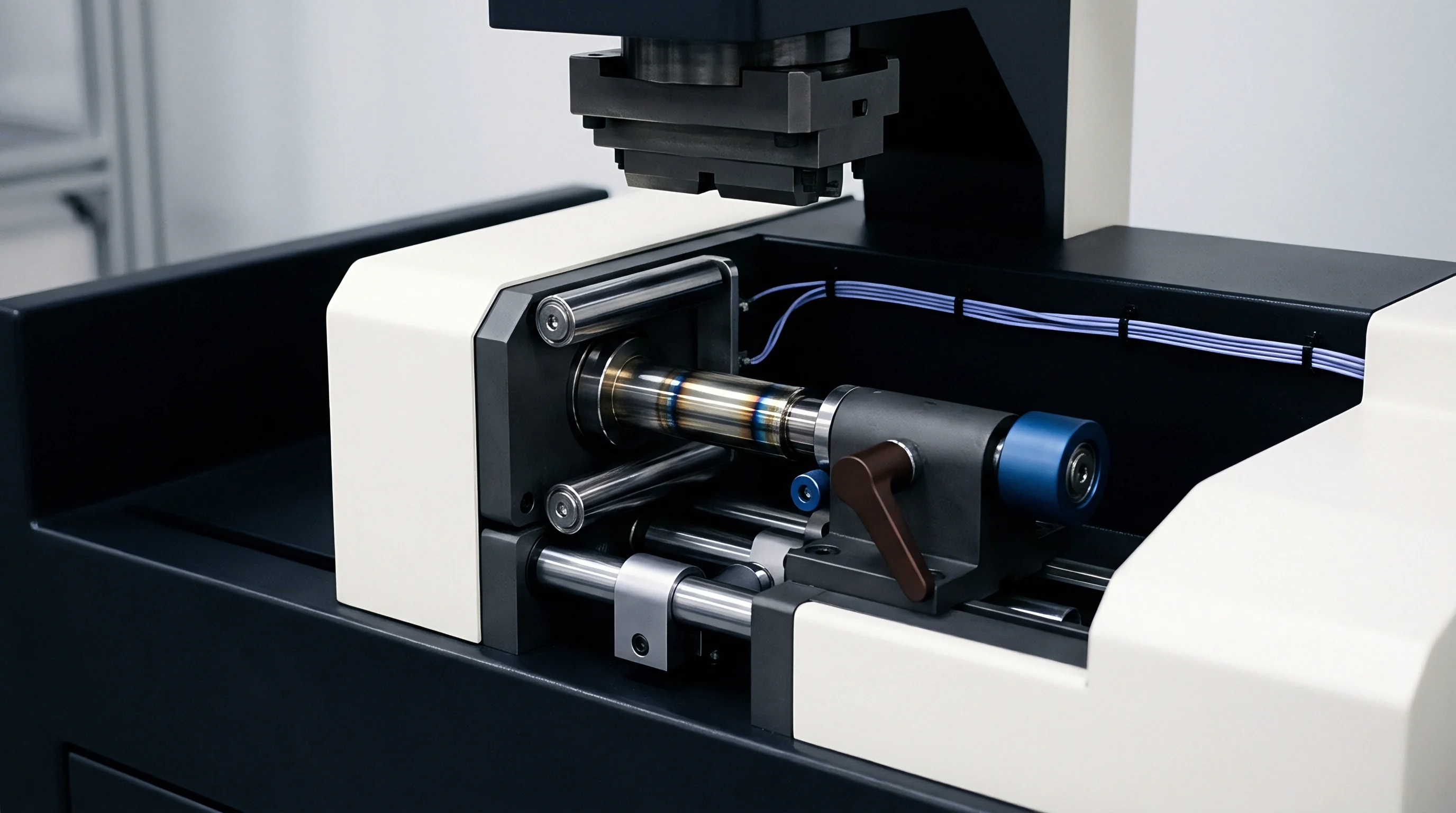
Damage
Life estimation models for terminal welds require formulation around local elastic-plastic strain energy densities rather than far-field nominal stresses. Because the weld root experiences plastic deformation even under moderate operational currents, strain-life methodologies incorporate cyclic plastic strain amplitudes alongside elastic components. The Coffin-Manson-Morrow equation provides the baseline relationship for total strain amplitude versus cycles to crack initiation.
Mean stress corrections account for residual stress fields left behind by the laser welding process. Rapid solidification of molten metal creates tensile residual stresses near yield strength levels inside the weld bead root. Positive mean stresses accelerate fatigue crack initiation and opening rates under cyclic displacement.
The Smith-Watson-Topper parameter handles these effects by evaluating the product of maximum stress and principal strain amplitude over each cycle.
- Extract nominal current and temperature profiles from pack vehicle drive cycles.
- Calculate cell core and terminal temperature distribution using localized electro-thermal lumped-parameter models.
- Translate thermal expansion and electrochemical swelling cycles into structural displacement vectors at busbar contact pads.
- Execute non-linear elastic-plastic finite element analysis to compute local notch stress and strain tensors at the weld root.
- Apply Rainflow cycle counting algorithms to decompose complex non-proportional strain time series into discrete hysteresis loops.
- Calculate cumulative fatigue damage sums using Miner’s linear damage rule combined with strain-life fatigue curves.
Fatigue crack growth prediction following initiation uses linear elastic fracture mechanics principles. The stress intensity factor range governs the crack propagation rate per cycle according to Paris law formulations. Crack propagation continues until the remaining uncracked ligament area can no longer support peak operating currents, resulting in sudden thermal runaway at the interface or open-circuit electrical failure.
Calculating life expectancies under complex operational duty profiles involves converting irregular load histories into damaging equivalent cycles, such as evaluating a prismatic cell header weld joint under combined daily operations.
Assume a vehicle pack undergoes two full fast-charge and discharge cycles daily alongside continuous minor power fluctuations. Finite element analysis of the weld root establishes a combined elastic-plastic strain amplitude of 0.0028 under full thermal and breathing displacement, accompanied by a localized mean tensile residual stress of 140 megapascals. The base aluminum alloy exhibits a fatigue ductility coefficient of 0.35, a fatigue ductility exponent of minus 0.60, a fatigue strength coefficient of 420 megapascals, and a fatigue strength exponent of minus 0.09.
Applying the Smith-Watson-Topper fatigue damage model evaluates the combined parameters against material properties. The calculated fatigue life for crack initiation under these specific operating conditions lands at approximately 14200 full charge-discharge cycles. Introducing a process-induced root notch defect that increases local stress concentration by twenty percent drops the predicted crack initiation threshold down to 4800 cycles.
This threefold reduction in service life demonstrates the severe sensitivity of weld root fatigue durability to manufacturing micro-geometry.
Designing busbars with geometric expansion loops lowers weld root displacement vectors.

Inspection
Detecting root notch anomalies prior to pack integration requires high-resolution non-destructive testing techniques capable of penetrating thick metal layers. Conventional optical surface inspection fails because weld root defects lie concealed beneath the top sheet layer within the overlap zone. Automated inline inspection systems evaluate real-time physical indicators generated during the laser welding process to flag substandard joints before assemblies advance down the NPI production line.
Acoustic emission sensing and photodiode signal tracking monitor keyhole stability during laser execution. Sudden back-reflection drops or abnormal acoustic spikes correlate with weld pool collapse and root blowout events. Post-weld quality verification utilizes ultrasonic testing and optical coherence tomography to measure actual fusion width and identify root gap dimensions along the entire seam length.
| Inspection Method | Inline vs Offline | Minimum Defect Size (µm) | Throughput Speed | Detection Capability | |
|---|---|---|---|---|---|
| Optical Coherence Tomography | Inline Real-Time | 15 | High (>200 mm/s) | Keyhole depth, root gap, top topography | |
| High-Frequency Ultrasound (50MHz) | Offline / Sampling | 25 | Low (Manual/Robotic) | Root crack initiation, un-fused lap width | |
| X-Ray Computed Tomography | Offline Metrology | 5 | Very Low (Batch) | 3D porosity, internal micro-cracks, root geometry | |
| Active Thermography | Inline Automated | 80 | Medium (Cell/Pack level) | Delamination, complete lack of root fusion |
Production line yield curves depend heavily on maintaining tight lap fit-up tolerances across incoming cell lots. Clamping fixtures must deliver uniform compression across terminal tabs during welding to eliminate air gaps. Gaps wider than fifty micrometers disrupt heat transfer during laser melt, producing severe root undercut and drastically reducing joint fatigue life.
Standard ISO 13919-2 Class B acceptance limits for beam welds mandate strict notch limits that disqualify poor penetration profiles.
Manufacturing process variations introduce localized material and structural flaws that accelerate fatigue failures at the header interface.
- Unfused Root Gap creates an unbonded crevice that acts as an aggressive primary mechanical stress raiser under bending load.
- Root Undercut reduces effective joint shear area and concentrates plastic deformation directly along the fusion boundary line.
- Keyhole Porosity forms spherical voids near the weld tail that trigger secondary fatigue crack sites under cyclic loading.
- Thermal Micro-Cracking originates in heat-affected zones during rapid cooling, weakening grain boundary cohesion near the root.
- Intermetallic Phase Precipitation occurs in dissimilar metal joints, creating brittle physical zones prone to low-cycle fatigue fracture.
Quality agreements that incorporate ISO 13919-2 Class B requirements force suppliers to reject weld lots exhibiting root undercut depths exceeding ten percent of sheet thickness. Enforcing this contractual clause prevents substandard penetration profiles from reaching assembly lines, shifting financial liability for joint failure back to the cell tab processor.

Bench
Physical verification of predicted weld fatigue life requires test rigs capable of synchronizing electrical power cycling with controlled mechanical displacement. Standard thermal chambers testing passive packs fail to reproduce actual operational stress states because thermal gradients across internal cell headers remain absent. Advanced test benches use direct current injection up to 1000 amperes alongside environmental temperature control to induce realistic thermal expansion inside cell terminals.
Dynamic testing at 85 degrees Celsius demonstrates a forty percent reduction in weld root fatigue limit compared to room temperature baselines.
Servo-hydraulic or electromechanical actuators attach to cell bodies to apply cyclic displacement loads matching electrochemical breathing profiles. Measuring displacement resolution down to single micrometers ensures accurate replication of pouch expansion under charge-discharge regimes. Synchronizing mechanical pulling forces with peak ohmic heating cycles creates real-world multiaxial strain profiles across the header joint.

How Does Test Acceleration Alter Weld Notch Root Plasticity?
Accelerating fatigue test schedules by increasing thermal ramp rates or cycling frequencies alters local material behavior at the weld root notch. High-frequency displacement testing eliminates creep relaxation mechanisms that naturally occur during slow field cycling. When test frequencies exceed real-world load rates, localized stress relaxation around the notch tip cannot occur, leading to overly conservative fatigue life estimates.
Temperature acceleration must remain within strict bounds to avoid changing underlying failure mechanisms. Testing above material recrystallization limits lowers material yield strength artificially, inducing plastic flow at strain levels that would remain purely elastic during normal field operation. Validated testing protocols limit maximum accelerated temperatures to ten degrees below maximum specified cell storage ratings while applying strain acceleration factors derived from strain-life curve slopes.
Comparing physical crack initiation times against non-linear finite element predictions highlights systematic errors in baseline material S-N curves. Un-welded parent material data consistently overestimates joint life by failing to account for heat-affected zone grain coarsening. Establishing accurate fatigue life prediction software requires feeding raw strain-life data extracted directly from micro-tensile specimens machined out of actual laser-welded header joints.
Unresolved questions remain regarding how multi-year chemical degradation of cell enclosure polymers alters mechanical boundary conditions around terminal feedthroughs. As sealing grommets age and lose elastic recovery, terminal pins experience shifted tilt angles, altering baseline bending moments at the busbar weld root in ways current accelerated testing rigs cannot simulate.

Allocation
Assigning engineering responsibility for header weld failures requires clear boundary definitions inside purchase specifications. Cell manufacturers frequently specify maximum allowable forces acting on terminal pins under static assembly conditions. Pack integrators must demonstrate that busbar expansion loops reduce dynamic operational forces below these published limits during combined thermal and breathing events.
| Interface Metric | Specification Limit | Responsible Party | Verification Method |
|---|---|---|---|
| Terminal Pin Max Angular Deflection | Less than 0.5 degrees | Pack Integrator | CAD Motion Analysis / FEA |
| Cell Tab Thickness Tolerance | +/- 0.020 mm | Cell Supplier | Incoming Optical Gauge |
| Weld Seam Penetration Depth | 70% to 85% of lower sheet | Assembly Process Owner | Destructive Cross-Section |
| Max Allowable Terminal Shear Force | 120 Newtons | Cell Supplier | Terminal Load Cell Pull Test |
Defining clear ownership over weld interface fatigue longevity demands structured technical metrics within supply contracts.
- Terminal Force Limits establish maximum allowable dynamic loads cell pins can experience without voiding cell-level warranties.
- Busbar Compliance Criteria define minimum mechanical flexibility requirements for interconnect structures across temperature ranges.
- Joint Penetration Standards mandate minimum fusion area boundaries necessary to handle operational current densities and mechanical fatigue.
- Fit-Up Tolerance Rules limit acceptable gap variations between tabs entering automated laser welding stations.
When a weld root fatigue fracture occurs in the field, forensic analysis evaluates whether terminal pin load limits were exceeded or whether process defects created premature notch failure. The compliance file must include non-linear structural stress simulations proving the busbar network maintains terminal loads below specified thresholds across all operating temperatures. Demonstrating compliance protects the pack integrator from warranty claims when micro-structural inspection reveals sub-surface keyhole voids or inadequate root penetration within failed cell shipments.