Coupled Electrochemical Aging under Non-Uniform Planar Battery Cooling Gradients
Planar cooling gradients split local current density, driving lithium plating at cold cell margins and rapid electrolyte consumption in warm regions.

Chill
Large-format lithium-ion cells operated against single-sided or bottom cold plates develop sustained planar temperature spreads between 5 K and 14 K during continuous 1C discharge. Heat generated inside the jelly roll or electrode stack conducts anisotropically through the cell body. In-plane thermal conductivity along copper and aluminum current collector foils reaches 300 W/m·K to 380 W/m·K, but through-plane conductivity across electrode coatings, separators, and electrolyte layers stays constrained between 0.4 W/m·K and 1.2 W/m·K. When coolant passages run along only one edge or the bottom face of a 100 Ah to 304 Ah prismatic can, the span from the top terminal region to the cooled base creates a permanent temperature gradient across the active electrode area.
Planar thermal gradients split the electrochemical load into parallel local current paths. Warmer electrode zones show higher electrolyte ionic conductivity and lower charge-transfer resistance at the solid-electrolyte interface, while cooler zones suffer from sluggish desolvation kinetics and slow solid-state lithium diffusion in the graphite. Across continuous copper and aluminum substrates, the cell effectively behaves as an array of parallel micro-cells, routing current wherever local impedance drops lowest.
Bottom-cooled 280 Ah prismatic cells under a 12 K base-to-terminal gradient divert 38 percent higher current density through the warm upper third of the jelly roll during the first twenty minutes of a 1C discharge.
Chilling the base plate pulls the bottom electrode boundary well below pack-average readings. A battery management system reading a single thermistor on the cell shoulder might register an acceptable 28 °C while the base sits at 16 °C. Lifetime projections derived from isothermal bench cycling break down here, because they assume a lumped thermal mass with uniform degradation kinetics.
Discrepancies between local heat generation and cold-plate heat rejection distort internal current paths across daily cycling. Ignoring these planar variations in thermal system design leads to early cell retirement as localized active material exhausts prematurely.

Skew
Temperature governs charge-transfer resistance and solid-state diffusion through standard Arrhenius relationships. Dropping 10 K doubles charge-transfer resistance at the graphite anode interface. The warm section of a cell therefore faces lower ohmic and kinetic overpotentials, pulling a disproportionate share of the total pack current during charge and discharge alike.

Electrochemical Kinetic Maldistribution
Maldistributed current density drives a widening split in local state of charge across the electrode sheet. The warmer upper zone of a tall prismatic cell discharges faster than the colder base, hitting its lower cutoff potential while the base retains residual capacity. On the recharge, that depleted warm section takes on current at higher rates until overpotentials equalize across the metallic current collectors.
These disparities persist during rest periods as internal balancing currents. Charge migrates through the collector foils from under-discharged cold zones into over-discharged warm zones long after external contactors open. This internal circulation accelerates capacity fade through parasitic side reactions without registering as external ampere-hour throughput.
| Electrode Position | Local Temperature (°C) | Charge Transfer Resistance (mΩ·cm²) | Local Current Share (Fraction of Mean) | Anode Overpotential vs Li/Li+ (mV) |
|---|---|---|---|---|
| Upper Shoulder (Near Tabs) | 38.2 | 18.4 | 1.34 | +62 |
| Mid-Body Active Area | 31.5 | 27.6 | 1.02 | +38 |
| Lower Base (Cool Plate Interface) | 22.1 | 46.8 | 0.64 | -14 |
Dynamic Overpotential Inversion
Fast charging with uneven cooling flips the risk profile across the cell geometry. Cool electrode regions near the bottom plate face elevated charge-transfer overpotentials at the graphite-electrolyte boundary. Once incoming current pushes local anode potential below 0 V against the lithium reference potential, metallic lithium starts depositing on graphite particle surfaces.
- Interfacial charge transfer resistance climbs at the cold boundary, forcing lithium ions to plate as metallic dendrites rather than intercalating into the graphite lattice.
- Localized state of charge divergence pushes the warm upper foil area onto higher voltage plateaus, accelerating transition-metal dissolution from nickel-rich cathode particles.
- Active material volumetric breathing develops unevenly across the jelly roll, inducing shear stress between expanding warm zones and lagging cold zones.
- Electrolyte consumption rates separate across planar coordinates, drying out separator pores in hot regions while cold zones accumulate dead lithium deposits.
Cool electrode boundaries accumulate metallic lithium while warm boundaries consume liquid electrolyte through parasitic film growth.
Cold electrode zones become permanent bottlenecks for fast charging acceptance. Standard constant-current constant-voltage protocols sized for the bulk average cell temperature drive these chilled sectors into irreversible lithium plating well before terminal voltage hits the upper regulation limit.
Thermal uniformity across the cell face dictates operational life far more strictly than the absolute average pack temperature.


Anode
Subjecting graphite negative electrodes to spatial temperature gradients establishes split aging regimes across a single continuous coating. At the chilled margin, lithium plating occurs at charge rates as low as 0.5C when the local temperature rests below 20 °C. The deposited lithium reacts irreversibly with alkyl carbonate solvents, forming high-impedance solid electrolyte interphase products and consuming the accessible cyclable lithium inventory.
Coupled Degradation Mechanisms
Near the uncooled terminal region, higher temperatures accelerate chemical decomposition of lithium hexafluorophosphate electrolyte salts. Elevated heat triggers continuous growth of the passivating surface film on graphite particles, trapping active lithium into thick organic and inorganic layers. The upper zone suffers rapid capacity fade through loss of lithium inventory, while the lower zone loses capacity through active site isolation and pore clogging.
Mechanical stress compounds degradation across the active layer boundary. Intercalation-induced volume expansion of graphite reaches roughly ten percent at full lithiation. As the warm zone cycles through deeper state-of-charge swings than the cold zone, localized mechanical stress concentrates along the transition boundary on the current collector foil.
Can Coolant Channel Layout Restrict Local Inhomogeneity?
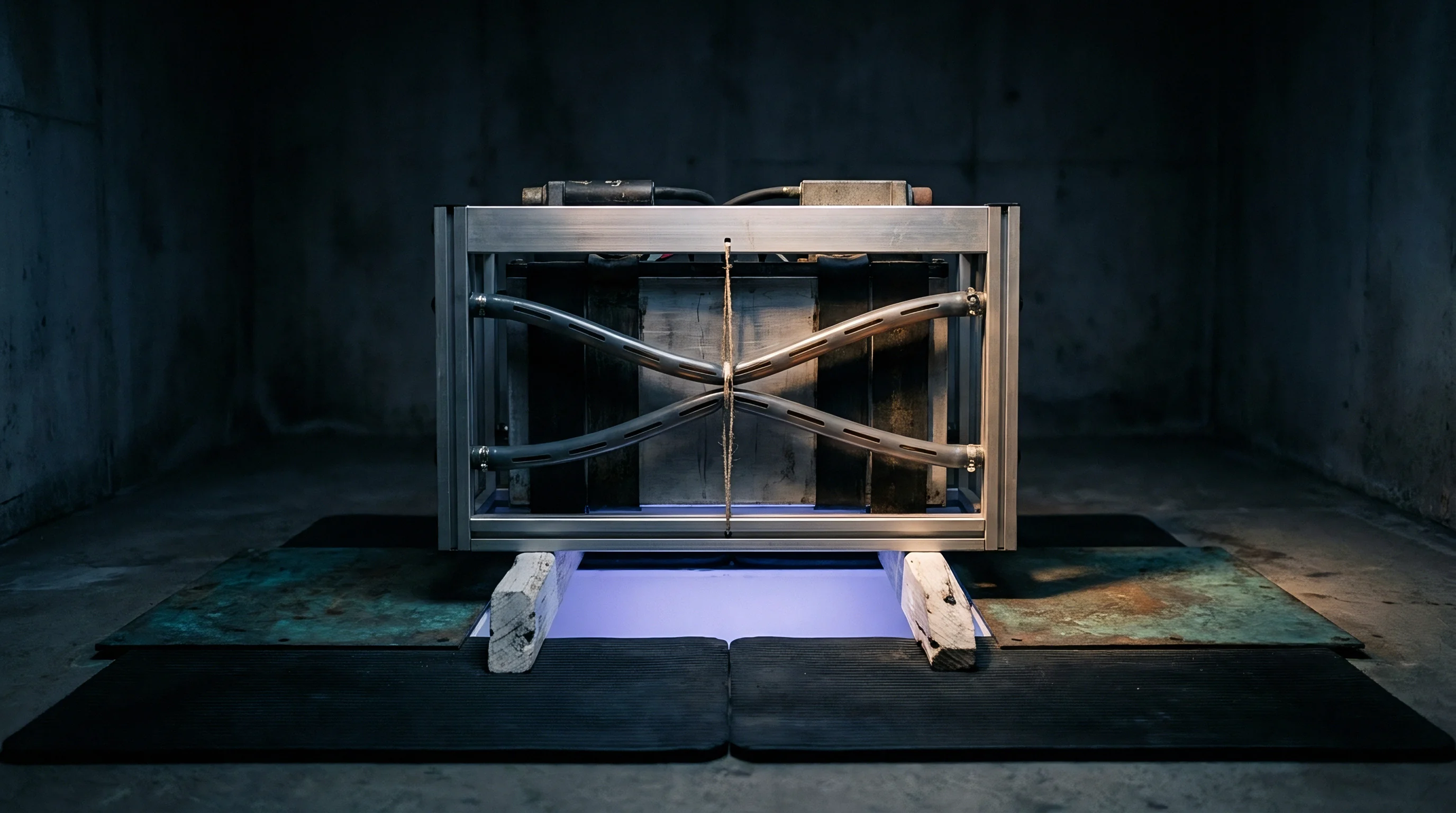
Serpentine and parallel channel cold plates generate distinct planar temperature fields that imprint directly on cell aging profiles. Serpentine configurations cause cumulative coolant heating along the flow path, creating a diagonal temperature gradient across adjacent cells in a module. Dual-pass counter-flow cold plates eliminate gross diagonal skew, restricting the maximum planar temperature difference to less than 3.5 K across the cell base.
Thermal interface material thickness variations of 0.3 mm create localized hot spots that skew current distribution across pristine cell groups.
Cyclic mechanical loads across these thermal boundaries lead to coating micro-cracks and binder delamination from the copper substrate. Copper current collectors show localized fatigue lines corresponding precisely to the temperature boundary lines mapped during initial thermal imaging tests. Separator membranes also experience non-uniform pore closure under localized high-temperature zones, driving permanent local resistance increases that remain after the pack cools down.
How current collector foil alloys and thickness profiles alter mechanical fatigue thresholds under cyclical planar temperature gradients remains open for long-term validation.


Yield
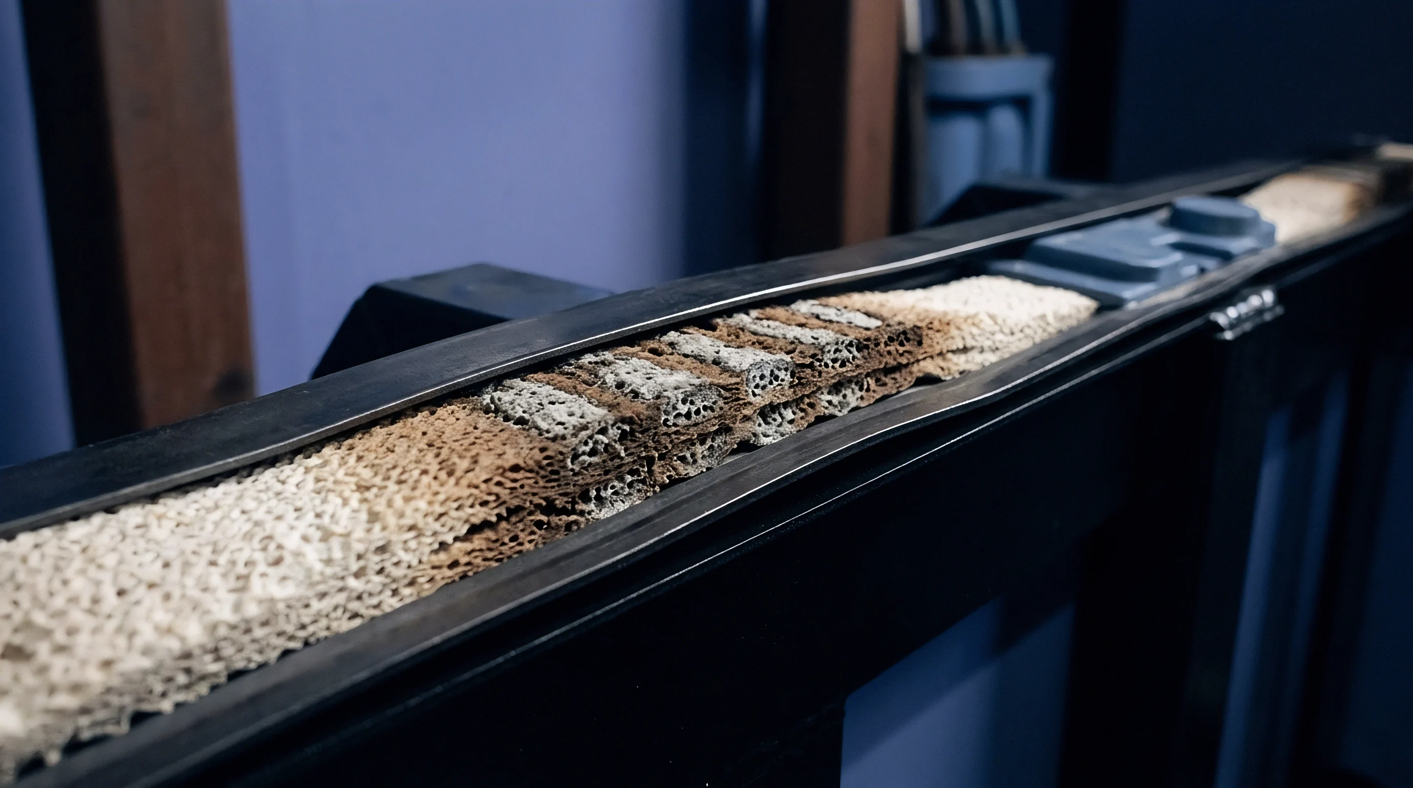
Pilot line manufacturing reveals these degradation patterns during destructive physical analysis of aged cells. Teardown inspections of 280 Ah prismatic cells cycled under base-cooled configurations reveal distinct visual and chemical banding across harvested electrode sheets. The bottom edge adjacent to the cold plate displays silver-grey metallic lithium plating streaks, while the upper active area near the tabs displays darkened, decomposed electrolyte varnishing.
Teardown Verification and Material Auditing
Inductively coupled plasma optical emission spectrometry confirms significant variation in cyclable lithium content across planar sections. Titration tests demonstrate that active lithium inventory loss accounts for 72 percent of total capacity fade in the warm zone, whereas active material isolation dominates in the cold zone. Scanning electron microscopy shows severe particle cracking in cathode material harvested from the high-current warm sector.
| Metric | Cold Base Zone (18 °C–24 °C) | Mid-Body Zone (25 °C–32 °C) | Warm Tab Zone (33 °C–41 °C) |
|---|---|---|---|
| Graphite Layer Thickness Increase | 14.8 percent | 8.2 percent | 6.1 percent |
| Metallic Lithium Content (g/m²) | 4.21 | 0.38 | 0.02 |
| SEI Layer Thickness by XPS (nm) | 22 | 41 | 68 |
| Retained Active Cathode Capacity | 91.4 percent | 86.2 percent | 78.5 percent |
| Delamination Force from Foil (N/m) | 18.5 | 24.2 | 14.1 |

Production Line Fixturing and Tolerances
Mechanical tolerance stack-up in module assembly directly drives thermal contact resistance variation across the cell surface. Variations in thermal interface material bondline thickness create localized insulation pockets, aggravating in-plane gradients. Tooling fixtures must maintain even surface compression to prevent localized thermal decoupling during operational swelling.
- Incoming cell can flatness inspection rejects prismatic enclosures showing face bowing beyond 0.25 mm across the wide side.
- Automated dispensing verification audits thermal interface material volume and wet-out area across the full cold-plate contact surface.
- Module compression rig calibration locks stack pressure between 0.20 MPa and 0.35 MPa to maintain uniform thermal interface resistance across all cell units.
- Multi-point thermal end-of-line testing validates temperature balance across base and shoulder sensors under a 20-minute 1.5C discharge pulse.
Thermal interface material voiding exceeding five percent of the cell contact area produces measurable degradation banding within two hundred cycles. Factory production yields depend on structural precision at the thermal interface as much as electrode coating consistency.
Cell-to-cell thermal management balances temperatures across a module, yet single-surface cooling geometries leave internal planar gradients unaddressed.
Warranty
Commercial contracts often divide liability cleanly between the cell manufacturer and the pack integration house. Cell manufacturers write warranty conditions assuming isothermal operation defined under standard testing standards such as IEC 62660-1 and UL 1973, which mandate ambient chambers held at 25 °C ± 2 K with minimal surface gradients. Pack integrators deploy those cells against single-sided cooling plates that generate internal planar gradients exceeding 10 K during routine field operation.
Seams in Sourcing Liability
When field returns exhibit premature capacity fade, suppliers routinely contest claims by performing standard laboratory capacity grading. If harvested cells meet the original specification under isothermal bench testing, the cell manufacturer disclaims liability, attributing the field failure to improper thermal boundary conditions maintained by the pack enclosure. The pack builder bears the landed cost of field replacements and warranty claims unless thermal operating envelopes are defined in the master supply agreement.
Master purchase agreements specifying cell operating temperature must define the maximum permissible temperature gradient across the cell surface alongside the bulk temperature limits.
Resolving warranty seam disputes requires establishing pre-agreed validation protocols during the initial RFQ stage. Sourcing teams define unambiguous boundary criteria covering both average operating temperature and maximum permissible in-plane thermal gradients across all cell faces.
- Thermal boundary annexes establish legal maximum temperature differentials across individual cell faces under peak continuous power profiles.
- Joint teardown protocols define standardized post-mortem test procedures for identifying localized lithium plating versus baseline homogeneous aging.
- BMS telemetry logging clauses mandate continuous monitoring and recording of multi-point surface temperature sensors across high-risk pack zones.
- Warranty remediation formulas allocate warranty replacement costs proportionally when operating logs demonstrate thermal gradient exceedance caused by pack-level cooling architecture.
Incorporating explicit temperature uniformity thresholds into standard procurement contracts binds the cell supplier and pack architect to a shared technical specification that survives field failure arbitration.