Liquid Gap Filler Compression Behavior under Cyclic Battery Module Swelling
Cyclic battery module swelling forces liquid gap filler squeeze-out and micro-voiding, driving up thermal impedance unless stress relaxation exceeds 40%.
Matrix
Dosing synthetic resins loaded with ceramic particulates between cooling plates and cell casings creates an essential heat pathway inside battery enclosures. Formulations rely primarily on two-part addition-cure silicones, single-part heat-cured organopolysiloxanes, polyurethane elastomers, and modified epoxy-acrylate hybrids. These polymers host heavy loadings of spherical alpha-alumina, hexagonal boron nitride, or aluminum trihydrate, reaching volumetric loading fractions between 55% and 68%.
High filler density grants thermal conductivity figures spanning 1.5 W/m K to 4.2 W/m K. Cell expansion during charge cycles forces this structural medium into severe, repetitive spatial displacement.
Cell swelling exerts steady force. Lithium intercalation expands cell dimensions along the stack axis, generating normal stress against adjacent module walls. As silicon-blend anodes or high-nickel cathodes cycle between zero and full state of charge, reversible volumetric swelling induces transient strains from 2% to over 8% within the interstitial gap.
The binder polymer responds through localized mechanical deflection, crosslink chain stretching, and microscopic polymer network rearrangements. Silicones maintain flexible siloxane backbones that resist permanent deformation under mild cycling. Polyurethanes offer superior initial tear strength but experience accelerated hydrogen-bond rearrangement under sustained thermal compression.
Polymer Backbone Resilience under Cyclic Mechanical Deflection
Repeated displacement alters the underlying molecular structure of cured elastomers. Under continuous compression-relaxation cycles, high thermal conductivity formulations show stress relaxation decay. Siloxane backbones resist permanent set.
Unreacted oligomers and low-molecular-weight silicone fluids squeeze out under peak mechanical loads, migrating toward structural boundaries. This fluid exudation leaves behind an increasingly dense filler network with lower elastomer compliance, escalating the bulk elastic modulus over thousands of operating hours.
| Chemistry Type | Filler Vol % | Conductivity (W/m K) | Compression Set (%) | Peak Strain Limit (%) |
|---|---|---|---|---|
| Two-Part Addition Silicone | 58 – 65 | 2.0 – 3.5 | 8.5 – 12.0 | 45.0 |
| One-Part Moisture-Cure Silicone | 52 – 60 | 1.5 – 2.8 | 15.0 – 22.0 | 35.0 |
| Two-Part Polyurethane | 55 – 62 | 1.8 – 3.0 | 18.0 – 28.0 | 30.0 |
| Epoxy-Acrylate Hybrid | 60 – 68 | 2.5 – 4.2 | 32.0 – 45.0 | 18.0 |
High crosslink density reduces initial creep rates while increasing the peak reaction force transmitted directly to neighboring prismatic cell walls. Conversely, under-cured or low-crosslink elastomeric matrices yield lower installation forces but suffer from irreversible plastic strain accumulation. Over extended cell operational lifespans, plastic accumulation causes clearance gaps during cell contraction phases at low state of charge.
Chemical formulators frequently attribute liquid gap filler interfacial separation to variation in cell casing surface energy rather than matrix chain breakdown under compression.
Exudation of plasticizers alters bulk thermal properties over extended cycling. When lightweight siloxane chains migrate away from compressed regions, local filler particle packing density increases. This shift slightly elevates local bulk conductivity while severely compromising material softness, leading to interfacial stress spikes during subsequent module expansion cycles.

Shear
Lateral material movement occurs whenever module walls compress thermal interface layers against rigid support structures. Expanding prismatic casing walls push liquid gap filler laterally toward module margins. The resulting velocity gradient across the material thickness creates an internal force profile governed by fluid viscosity and dynamic boundary friction.
Dynamic compression testing demonstrates that maximum lateral displacement concentrates at the center of large cell faces, forcing compound toward perimeter fluid channels.
Gap dimensions shift constantly. Volumetric strain accommodation requires understanding the complete mechanical stack-up inside a battery assembly. An evaluation using a 12-cell prismatic battery module illustrates the physical mechanics involved during operation.
The module features individual cell dimensions of 220 mm width by 100 mm height, separated by nominal 1.20 mm gap filler channels with a tolerance of plus or minus 0.15 mm. Charging expansion induces 0.20 mm of reversible transverse expansion per cell face across the stack, producing a total module displacement delta of 2.40 mm against fixed structural end plates. Compression strain inside the gap filler channels reaches 33.3% at 100% state of charge.

Interfacial Displacement Mechanics and Boundary Squeeze Out
Volumetric calculations reveal that peak displacement forces approximately 0.28 cubic centimeters of compound out of each interstitial gap during every full charge cycle. Over 1,200 standard charge-discharge cycles, this reciprocating pressure gradient creates an interfacial shear stress peak of 0.82 MPa at the outer perimeter edges. Viscous resistance during rapid fast-charging expansion events raises internal hydrostatic pressure inside the gap filler, driving local void formation during the subsequent discharge cycle when cell walls retreat faster than the compound can elastomeric recovery expand.
Thermal resistance rises with voiding. Experimental profiling shows that cumulative squeeze-out and micro-voiding reduce effective thermal contact area across the cell face by 16.5% after 1,500 full depth-of-discharge cycles. Junction-to-chassis thermal resistance increases from an initial benchmark of 0.21 Kcm2/W to 0.49 Kcm2/W. This impedance rise elevates peak cell operational temperatures by 6.8 degrees Celsius under identical 2C fast-charging load profiles, forcing BMS thermal management software to throttle power early.
A 16.5 percent loss in thermal contact area doubles interfacial thermal impedance and forces premature battery power throttling during fast charging.
Cell swelling mechanics demand rigid material limits to preserve long-term operational integrity.
- Interfacial Pump-Out Lateral extrusion driven by cyclic normal pressure forces material past enclosure boundaries, leaving depleted dry zones across central heat generation areas.
- Cohesive Shear Fracture Dynamic strain exceeding the material ultimate shear strength creates internal micro-cracks along maximum shear stress planes within the binder matrix.
- Phase Separation High mechanical pressure gradients drive liquid resin away from packed ceramic filler clusters, yielding unbonded abrasive dry filler pockets.
- Interfacial Debonding Loss of adhesive contact at the metal cell wall interface during cell contraction phases creates insulating air gaps that destroy heat dissipation pathways.
Neglecting dynamic mechanical shear behavior during filler selection leads to structural enclosure distortion, thermal throttling during fast-charge events, and accelerated cell capacity roll-off.
Rheology
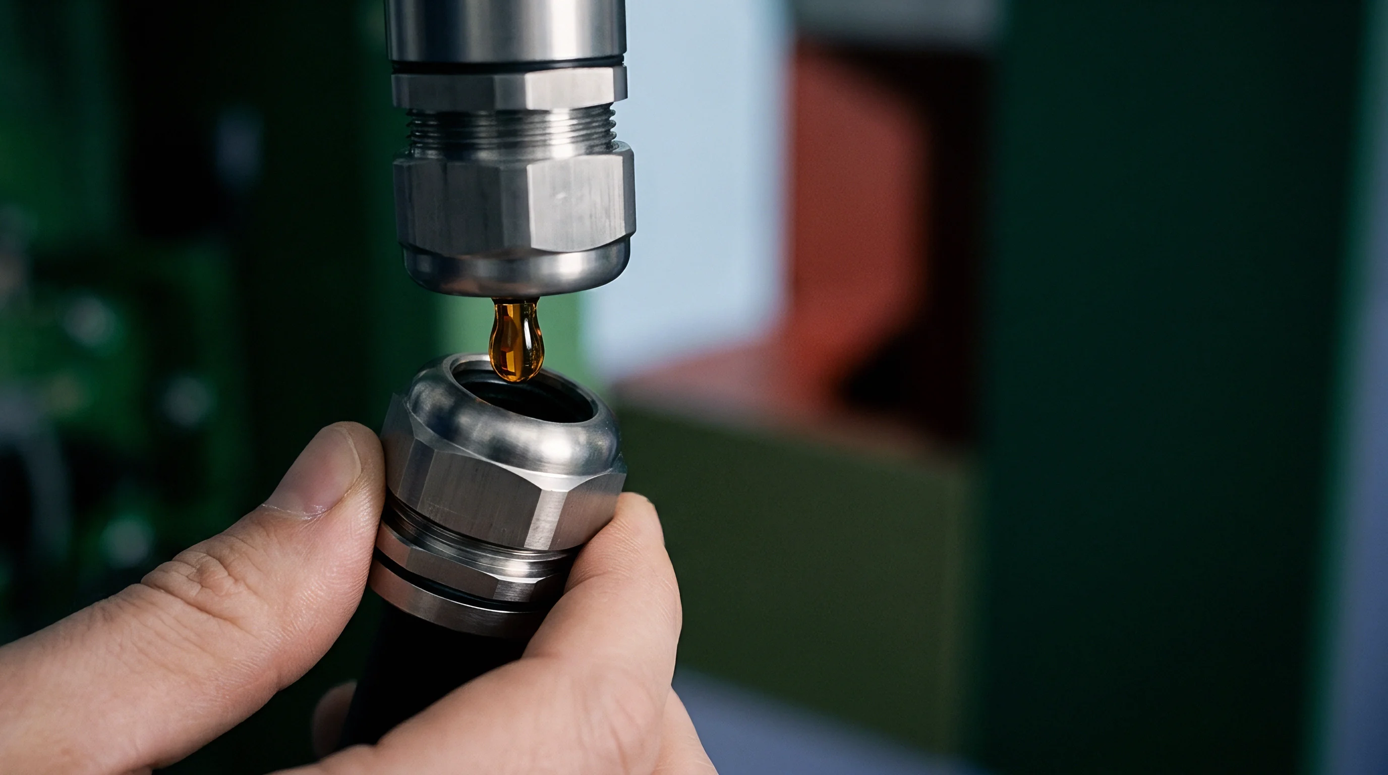
Non-Newtonian flow properties govern compound response during high-speed thermal expansion events. Thermally conductive gap fillers display thixotropic pseudoplastic behavior, where shear viscosity decreases significantly as shear strain rate increases. During rapid charging or high-temperature excursions, high expansion rates force high shear rates inside the gap filler layer, temporarily reducing flow resistance and accelerating extrusion velocity toward boundary edges.
Yield stress governs initial flow. Below the critical yield stress threshold, the material behaves as a viscoelastic solid, storing mechanical energy elastically without macroscopic displacement. Once compressive forces generated by cell breathing cross this yield stress limit, viscous flow mechanisms engage, initiating permanent material relocation.

Viscoelastic Relaxation Spectrum and Dynamic Storage Modulus
Characterizing viscoelastic properties involves tracking the dynamic storage modulus G prime and loss modulus G double prime across frequency strain sweeps from 0.01 Hz to 10 Hz. Dynamic strain sweeps establish the linear viscoelastic region where structural polymer networks remain intact. When compressive strains exceed 15%, the storage modulus drops sharply, marking the onset of structural network breakdown known as the Payne effect.
Relaxation kinetics determine how rapidly internal compressive forces dissipate after cell expansion reaches its peak. A formulation displaying rapid stress relaxation lowers the peak mechanical load on prismatic cell casings, protecting internal electrode stacks from mechanical crushing. Maxwell viscoelastic model fitting shows that relaxation time constants between 12 seconds and 85 seconds provide effective force dissipation during typical 0.5C to 2C charging cycles.
Filler Particle Alignment under Reciprocating Displacement
Reciprocating strain re-orients non-spherical ceramic particles suspended within the polymer matrix. Hexagonal boron nitride platelets align parallel to the plane of shear under continuous cyclic displacement. While parallel alignment reduces bulk shear viscosity, it creates anisotropic thermal conductivity profiles, dropping heat flow perpendicular to the cell surface while increasing heat conduction along the lateral extrusion axis.
Orderly execution of rheological verification protocols protects against catastrophic in-service displacement.
- Mount a 1.0 mm cured compound sample between parallel serrated plates on a rotational rheometer equipped with normal force transducers.
- Execute an amplitude strain sweep from 0.01% to 100% strain at a fixed frequency of 1.0 Hz under controlled isothermal conditions at 25 degrees Celsius.
- Record the critical strain threshold where storage modulus G prime drops by 10% relative to initial linear elastic response levels.
- Perform a multi-step stress relaxation test applying a step compressive strain of 20% while capturing normal force dissipation over 3,600 seconds.
A high loss modulus relative to storage modulus preserves interfacial wetting across repeated expansion cycles without inducing mechanical strain peaks on cell side walls.
Higher loss modulus values absorb displacement energy through viscous dissipation, mitigating elastic rebound stresses during rapid contraction phases.


Fatigue
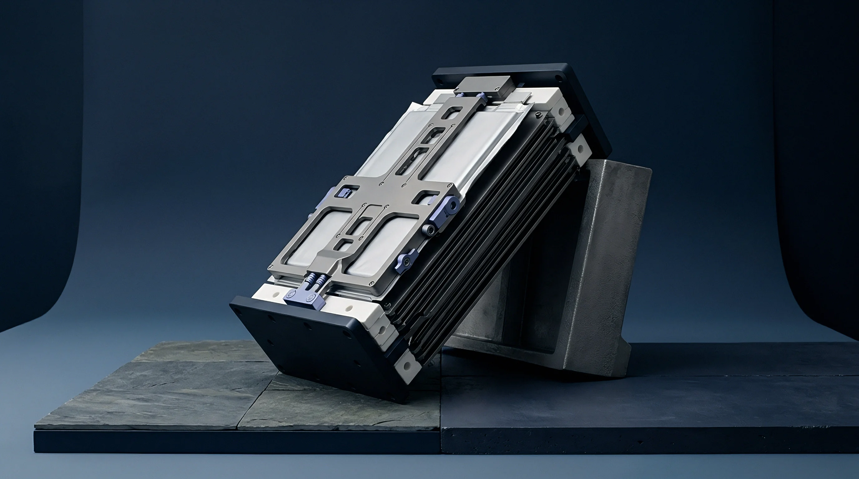
Long-term mechanical endurance testing requires simulated module fixtures operating inside environmental test chambers. Combined thermal and mechanical strain testing reproduces true automotive and stationary storage operational stress environments. Electromechanical test frames push module mock-ups through sinusoidal strain cycles matching real cell breathing profiles while controlling temperature from minus 40 degrees Celsius to 85 degrees Celsius.
Cold temperatures elevate matrix stiffness. Reduced elastomer mobility at sub-zero temperatures increases storage modulus by up to two orders of magnitude, turning compliant gap fillers into rigid solids that transfer massive mechanical forces directly into aluminum cell casings.
Which Dynamic Strain Rates Cause Interfacial Delamination?
High strain rates applied at low ambient temperatures generate severe tensile stress spikes along cell bonding interfaces during contraction phases. When the cell wall retreats faster than the stiffened polymer matrix can elastically rebound, adhesive bond failure occurs. Micro-cavities nucleate at these unbonded regions, merging into wide air voids over several hundred thermal-mechanical cycles.
| Test Temperature (°C) | Strain Rate (%/s) | Cyclic Strain (%) | Void Area (%) | Dielectric Hold (kV) |
|---|---|---|---|---|
| 25 | 0.05 | 15.0 | 1.2 – 2.5 | 12.5 |
| 25 | 0.50 | 30.0 | 4.5 – 8.0 | 9.8 |
| -20 | 0.05 | 15.0 | 6.0 – 11.2 | 7.2 |
| -20 | 0.50 | 30.0 | 18.5 – 28.0 | 2.1 |
Pumping out leaves air pockets. Air pockets severely degrade electrical insulation performance across the thermal pad interface. Dielectric breakdown strength drops precipitously as air void fraction rises, threatening high-voltage isolation between cell casings and grounded pack cold plates.
Dielectric margin degrades rapidly.
- Volumetric Creep Allowance Quantitative measurement of permanent material displacement following 2,000 standard deflection cycles under maximum operating temperature.
- Interfacial Void Fraction Surface area percentage of unbonded air gaps detected via acoustic microscopy or thermal imaging following mechanical endurance testing.
- Retained Clamping Force Residual normal force exerted by the gap filler layer against cell faces at minimum state of charge following extended cycling.
- Dielectric Withstand Voltage Minimum electric field strength maintained across the compressed gap filler layer without experiencing electrical arc breakdown.
Standard quality clauses require zero void growth exceeding 5% total interface area after 1,000 continuous combined thermal-mechanical strain cycles.
Unresolved questions persist regarding the exact microscopic threshold where void coalescence converts localized thermal resistance jumps into full catastrophic electrical arc breakdown during cold-weather fast charging.

Outlay
Processing logistics and dispense tooling economics determine the final landed cost of thermal management implementations. High filler loading numbers essential for target thermal performance create severe abrasive wear inside dispensing equipment. Abrasive alpha-alumina and boron nitride particles erode progressive cavity pumps, dispense valves, and stainless steel nozzle tips, requiring specialized tungsten carbide component upgrades.
Dispense nozzle wear drives expense. Volumetric dosing drift caused by pump wear creates wide material thickness variations across the module assembly line. Under-dispensing leaves dry thermal voids, while over-dispensing causes excessive squeeze-out that contaminates cell terminal busbars and electrical interconnects, generating expensive factory scrap.
Dispensing Line Economics and Abrasion Amortization
Formulation choices dictate long-term production overhead and line maintenance cadences. Single-part moisture-cure silicone gap fillers remove two-component static mixing head complexity but require expensive heated supply lines and climate-controlled storage rooms to prevent premature curing. Two-part room-temperature addition-cure silicones eliminate cure oven energy costs but demand high-precision volumetric metering pumps to preserve proper stoichiometry under high line takt speeds.
Amortizing dispense equipment maintenance costs across high-volume production runs requires factoring valve rebuild intervals every 50,000 to 120,000 dispense strokes depending on filler particle shape and hardness. Spherical alumina fillers extend pump component operational lifespans by three times compared to jagged, irregular alumina particles, directly lowering line maintenance expenditures.
Warranty terms demand clear boundaries. Establishing strict engineering drawing notes regarding allowable squeeze-out volume limits and interfacial coverage percentages ensures clear quality ownership between material suppliers, module assemblers, and pack integrators.
Module purchasing contracts incorporating section 8.4 thermal interface durability provisions specify that material formulators hold full financial liability for cell thermal degradation whenever interface squeeze-out exceeds 10% volumetric loss under verified supplier-approved swelling limits.