Module Structural Frame Deflection Limits under Dynamic Lithium Plating Strains
Dynamic lithium plating strains require module frames engineered to span-over-800 deflection limits to prevent busbar weld fatigue and casing yield.

Strut
Channel data on a 150-ampere-hour prismatic cell charged at 2C below 10 degrees Celsius logs a localized face displacement velocity of 14 micrometers per minute. Slow intercalation expands standard graphite staging by roughly nine percent in volume. When rapid kinetic driving forces exceed the negative electrode’s acceptance rate, solid-state lithium inventory shifts into metallic surface deposition instead.
This metallic phase accumulates perpendicular to the electrode plane, driving severe local normal forces against the inner cell wall.
Module frame perimeter beams experience bending moments driven by distributed planar pressure rather than isotropic expansion. If metallic deposition starts along electrode edges from current density crowding, the displacement field becomes sharply non-uniform, with local strains reaching three times the amplitude of standard state-of-charge expansion waves. Frames designed only for uniform intercalation swell can yield at corners and tie points during low-temperature fast charging.

How Do Plating Overpotentials Alter Local Displacement?
Anode potential drops below zero volts against lithium reference electrodes when charge transfer resistance and solid-electrolyte interphase impedance restrict ionic transport. Lithium metal nucleates in planar and mossy forms right on carbon particle surfaces. Metallic lithium has a specific volume of 13.0 cubic centimeters per mole ~ far different from the graphite host expansion profile ~ creating a hard mechanical wedge between the separator and current collector foil.
Pressure rises to 0.82 megapascals within four minutes of continuous negative overpotential during 3C charging at 5 degrees Celsius.
Internal pressure rises sharply along the perimeter of the electrode stack, and the rigid casing transfers that localized thrust straight to the module end plates and longitudinal tension straps. The load trajectory follows an exponential curve rather than the linear trajectory of steady-state staging. This strain acts as an active boundary deflection, pushing the outer module skin beyond its elastic limit.
How the surrounding frame reacts determines whether metallic dendrites pierce the separator or compress into open electrode porosity. Stiff frames maintain high contact pressure, suppressing mossy growth but accelerating separator creep. Flexible frames allow casing bulge; that lowers mechanical pressure on the interface, but risks fatigue failure at internal tab welds and external busbars.
Where frame compliance shifts from helpful pressure relief to destructive strain on interconnects remains undocumented across different cell aspect ratios.
Girder
Sizing structural beams in a multi-cell battery module means balancing packaging efficiency against flexural rigidity. Longitudinal side members and transverse crossbars take combined axial tension and out-of-plane bending loads when cells expand non-uniformly during fast charging. Deflection along the neutral axis creates severe angular misalignment at terminal posts and cell interconnects.
Beam deflection limits set the mechanical boundaries for the whole electrical architecture. An extruded aluminum side channel supporting twenty-four 100-ampere-hour prismatic cells deflects cumulatively along its unsupported span. Calculating maximum allowable mid-span deflection requires modified Euler-Bernoulli beam equations with continuous elastic foundations.
Keeping deflection under span divided by 800 protects ultrasonic weld integrity at busbar interfaces.
Weld fatigue cracks form quickly once relative displacement between adjacent cell terminals exceeds 65 micrometers. Flexible laminated copper busbars absorb minor thermal movement, but they shear if out-of-plane frame bulge rotates cell terminals outward beyond 0.8 degrees. Side girders need an area moment of inertia large enough to arrest that rotation before exceeding the busbar’s elastic strain envelope.
| Material Grade | Yield Strength (MPa) | Elastic Modulus (GPa) | Section Deflection at 12 kN (mm) | Angular Distortion (deg) |
|---|---|---|---|---|
| EN AW-6060-T6 Extrusion | 150 | 69.5 | 1.42 | 1.12 |
| EN AW-6082-T6 Structural Profile | 260 | 70.0 | 0.88 | 0.54 |
| EN AW-7003-T6 High-Strength Alloy | 310 | 71.0 | 0.74 | 0.41 |
| 1.4301 Stainless Steel Formed Sheet | 230 | 200.0 | 0.31 | 0.18 |
Deflection values dictate material selection in structural evaluations. High-yield aluminum alloys allow thinner walls without sacrificing cross-sectional inertia, whereas roll-formed stainless steel sections offer high stiffness at the cost of added pack weight.
Frame rigidity directly governs pressure distribution on internal jelly rolls. Excessive stiffness without compliant foam inserts creates local stress hotspots up to 2.5 megapascals at the cell casing radius. These peaks crush the porous ceramic coating on polyethylene separators, causing ionic conductivity to drop sharply in compressed zones and forcing current into neighboring electrode areas, which triggers secondary plating.
Frame flexure determines internal stress distribution across cell layers.
Calculating loads requires modeling the pack as an interdependent system where cell compliance interacts with chassis deflection. Finite element software often treats the cell block as a passive solid brick, but real cells behave like active pressure vessels, pushing variable, rate-dependent, hysteretic forces against retaining girders.
Structural rails must withstand cyclic strain without accumulating plastic deformation. Cyclic plating and stripping generate an alternating mechanical stress pattern. Frames with low yield margins undergo ratcheting strain, creeping outward with each fast-charge cycle until internal cell compression falls below operational thresholds.
Rigid containment beams prevent electrical disconnects, and flexible mountings protect separators from crushing.
Yield
Casing walls fail through distinct mechanical pathways when dynamic plating strains overwhelm external structural restraints. Prismatic cells use aluminum skins between 0.6 and 1.2 millimeters thick, while pouch cells rely on multi-layer polymer-aluminum laminate films under 160 micrometers across their total cross-section. These thin envelopes function as hermetic seals rather than primary load-bearing members.
Stress concentrates mainly at the transition fillets of deep-drawn prismatic cans. Unconstrained expansion forces broad faces to pillow outward, pulling narrow side walls inward. This concave distortion creates high shear stress along the enclosure’s interior corners, thinning the aluminum over repeated high-rate charging cycles.
Pouch cells experience a different failure mode under unchecked frame deflection. Edge seals face concentrated peel stress when internal gas evolution accompanies uneven metallic deposition. Without calibrated planar compression, the aluminum barrier layer delaminates from the inner polypropylene film, creating moisture pathways that degrade electrolyte stability within dozens of cycles.
- Prismatic Casing Plastic Buckling causes permanent shell wall thinning along vertical corner fillets and micro-cracking at laser-welded bottom seams.
- Pouch Seal Delamination Shear tears the internal polypropylene bonding layer under unopposed lateral expansion forces exceeding 18 newtons per millimeter.
- Separator Pore Closure Rupture isolates active cathode areas by collapsing sub-micron void spaces under localized mechanical pressures greater than 1.8 megapascals.
- Current Collector Foil Tearing fractures interior copper tabs from differential axial displacement between the rigid electrode center and expanding perimeter plating zones.
Internal component degradation progresses silently long before the outer enclosure ruptures. When localized plating pressure crushes the micro-porous separator matrix, ionic transport stops across that interfacial zone. Current shunts into unblocked electrode areas nearby, worsening current density crowding and amplifying subsequent plating spikes.
A contract clause guaranteeing frame stiffness within span over 600 limits premature internal tab tear-out during winter charging cycles.
Structural failure at the module boundary feeds directly into cell-level degradation. A frame that deflects beyond allowable limits lets center cells expand freely while over-constraining perimeter cells. Center cells lose active stack pressure, causing rapid delamination and capacity loss, while outer cells endure crushed separators and accelerating impedance.
Ignoring structural deflection calculations leads directly to field recalls driven by thermal runaway from internal micro-shorts.

Tie
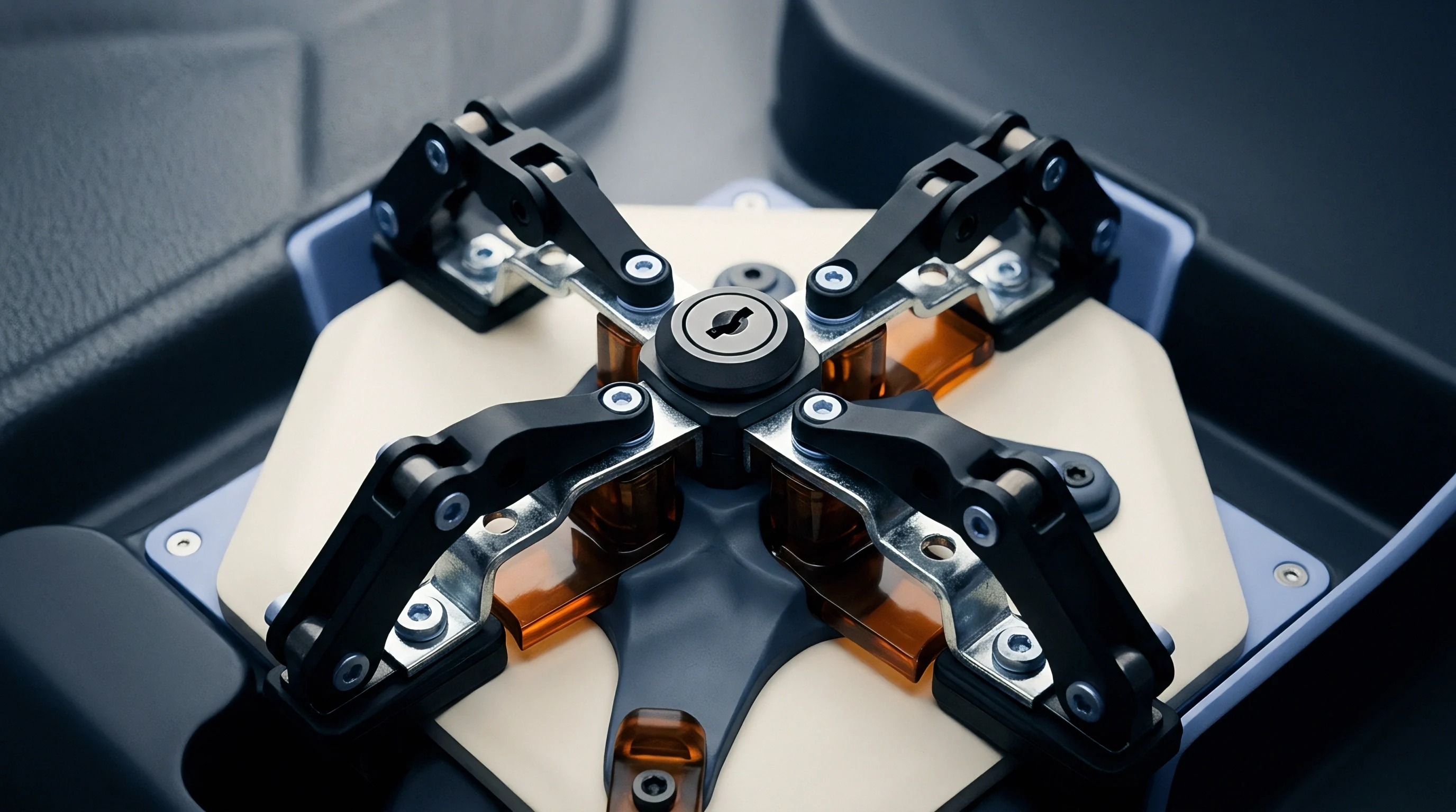
Tension members maintain critical pre-loads across the battery module stack. Modules use side straps, longitudinal threaded rods, or laser-welded wrap-around sheets to balance expansion forces from dynamic lithium deposition. Sizing ties requires accounting for both static assembly pre-stress and peak operational strain vectors.
Preload values establish baseline interfacial contact through initial formation cycles. Setting assembly pre-stress at 0.3 megapascals prevents active material shedding during early lithiation. When plating begins under rapid charging, tension members must absorb the surging outward force without yielding plastically.
Threaded steel tie rods face heavy fatigue under repeated fast charging. High-strength alloy steel rods resist permanent elongation, and specifying rolled threads instead of cut threads improves fatigue life under cyclic tensile spikes. Laser-welded 304 stainless steel side bands offer better packaging efficiency but tolerate less over-strain.
Does End Plate Compliance Suppress Internal Delamination?
Cast aluminum end plates provide flexural rigidity at module extremities, spreading tension member clamp loads across the full surface area of adjacent cells. However, flat plate profiles deform into convex shapes under high center pressure, concentrating force along cell edges while relieving pressure at the core.
| Profile Architecture | Web Thickness (mm) | Rib Array Pitch (mm) | Center Deflection at 15 kN (mm) | Weight Penalty (g) |
|---|---|---|---|---|
| Solid Flat Plate Al 6061-T6 | 12.0 | N/A | 1.22 | 840 |
| External Grid Ribbed Al 6082-T6 | 4.5 | 25.0 | 0.48 | 520 |
| Internal Honeycomb Die-Cast AlSi10Mg | 3.0 | 15.0 | 0.32 | 460 |
| Formed High-Strength Steel Ribbed | 2.5 | 30.0 | 0.28 | 610 |
Rib patterns optimize mass and stiffness simultaneously. Diagonal cast ribs route central thrust outward to corner tie-rod mounting bosses, flattening the pressure profile across the terminal cell face.
Compliant foam layers placed between cells modulate load transfer to the structural frame. Microcellular polyurethane foams follow non-linear compression-deflection curves, absorbing sudden plating expansion and keeping load spikes from hitting rigid side girders and end plates directly. Selecting appropriate foam density maintains interfacial pressure between 0.15 and 0.80 megapascals across the operational strain range.
- Pre-Stress Calibration establishes initial stack compression using load-cell equipped hydraulic clamping tables during end plate fastening.
- Dynamic Dilatation Absorption compresses the elastomeric pads during transient plating episodes, shielding side bands from peak tension.
- Elastic Recovery Recoil restores stack compression as reversible lithium strips back into the graphite host during discharge steps.
- Creep Strain Accommodation retains minimum clamping force across five years of calendar aging and plastic material relaxation.
Elastomeric compression pads reduce dynamic plating loads on structural side bands, but end-plate deflection limits remain necessary.

Covenant
Structural compliance requirements define the legal and operational boundaries between tier-one cell suppliers, pack assemblers, and vehicle integrators. Mechanical interface drawings specify allowable face pressures, peak deflection limits, and tie-rod fatigue limits. Ambiguous phrasing around dynamic versus static expansion often triggers warranty disputes when field failures occur.
Purchase specifications define the exact charging envelope required to keep module mechanical warranties valid. Sourcing contracts lay out thermal, electrical, and mechanical boundary conditions. If an integrator fast-charges cells below the temperature threshold set in the cell master agreement, dynamic plating strains void the cell supplier’s structural casing warranty.
A measured mid-span frame deflection of 0.45 millimeters under 2C charge at zero degrees Celsius verifies the structural safety factor for high-rate logistics operations.
Cell manufacturers require customers to maintain uniform face pressures within tight margins throughout the product’s lifespan. Meanwhile, module frame builders guarantee that structural deflection under peak transient plating forces will remain within set spatial limits. Without clear contract boundaries, module builders blame cell swelling for frame failure, while cell suppliers blame internal separator collapse on excessive frame rigidity.
Verification protocols require combined electrochemical-mechanical testing on full module assemblies. Incoming inspection uses laser profilometry scans of modules cycled under rapid low-temperature charging. First-article validation records out-of-plane frame deflection over five hundred continuous high-rate cycles inside environmental chambers, proving structural compliance through synchronized displacement and electrical telemetry data.
Section 7.4 of the standard master supply agreement stipulates that any unapproved alteration to side strap torque specifications shifts total product liability for cell casing rupture entirely to the pack integrator.