Quantifying Microscale Decohesion Fatigue Thresholds under Pouch Cell Stack Restraint
Optimizing pouch cell stack restraint pressure between 0.15 and 0.45 MPa suppresses binder-foil micro-decohesion fatigue while accommodating cyclic swelling.


Adhesion
Lithiation of high-capacity silicon-graphite blended composite anodes drives macroscopic thickness alterations reaching 8 to 22 percent at the cell level during full state-of-charge cycling. When a pouch cell operates inside a rigid or semi-rigid structural pack enclosure, external mechanical restraint converts volumetric expansion into high internal compressive and shear stress fields across the multi-layer electrode laminate. Microscale decohesion fatigue occurs when cyclic interfacial shear stresses exceed the mechanical endurance limit of the binder-particle network or the active-layer-to-current-collector interface, causing microscopic debonding long before catastrophic structural failure appears.

Electrode Swelling Kinematics under Uniaxial Displacement Constraints
Volume shifts during lithium insertion create localized strain mismatches inside composite porous electrodes. Active graphite particles exhibit anisotropic crystal lattice expansion up to 10 percent along the c-axis, while sub-micron silicon domains experience isotropic volume variations reaching 300 percent. In an unconstrained cell format, these micro-dilatations sum across the laminate thickness, driving overall pouch expansion.
When stiff endplates block displacement, microscopic stress fields build up at the contact points between rigid active material granules and the polymer binder matrix.
Particle displacement drives local shear. The structural integrity of the composite coating depends on styrene-butadiene rubber and carboxymethyl cellulose binder bridges operating in tandem with conductive carbon networks. Under cyclic mechanical load, localized shear strain amplitudes at the copper current collector interface fluctuate in direct phase with the cell state of charge.
Repeated loading weakens the polymeric physical crosslinks, initiating micro-void nucleation along particle surfaces.
The initial interface fracture resistance of a coated graphite-silicon anode drops from 48 Joules per square meter to less than 14 Joules per square meter after 600 full equivalent cycles under a fixed 0.30 Megapascal pre-charge clamp.
Interface degradation follows distinct micro-mechanical regimes driven by local normal stress magnitude. Below 0.15 Megapascal of external restraint pressure, active particles undergo out-of-plane micro-displacement, leading to coating buckling and localized delamination from the current collector. Above 0.80 Megapascal of constant mechanical compression, binder chains undergo irreversible compressive plastic deformation, crushing the interstitial pore volume, inhibiting electrolyte transport, and inducing particle cracking.
Optimizing long-term mechanical survival requires bounding the interfacial stress field inside a narrow operational pressure corridor throughout the service life of the pack.

Interfacial Shear Fatigue Failure Mechanics
Repeated electrochemical cycling forces micro-scale shear slip along the boundary separating the active coating layer from the surface-treated copper foil. Micro-decohesion initiates at microscopic surface flaws, burrs, or uneven binder distributions left behind by slot-die coating processes. Continuous shear movement degrades the mechanical interlocking between the porous composite deposit and the current collector micro-roughness.
- Primary Particle Debonding occurs when localized shear stress overcomes the adhesion energy of the binder, severing active silicon and graphite granules from the conductive matrix.
- Collector Delamination propagates horizontally along the copper interface, creating electrical isolation zones where current density spikes across adjacent intact contact points.
- Cohesive Binder Shear Creep accumulates during sustained high state-of-charge holding periods, causing permanent microstructural reorganization of the polymer network.
- Coating Micro-Cracking originates at delamination fronts, extending vertically through the coating thickness and exposing fresh metallic surfaces to continuous solid-electrolyte interphase growth.
Mechanical boundary conditions govern cell life. Maintaining interface integrity over thousands of deep discharge cycles demands matching the mechanical compliance of the cell restraint system to the internal decohesion fatigue threshold of the composite coating.

Foam
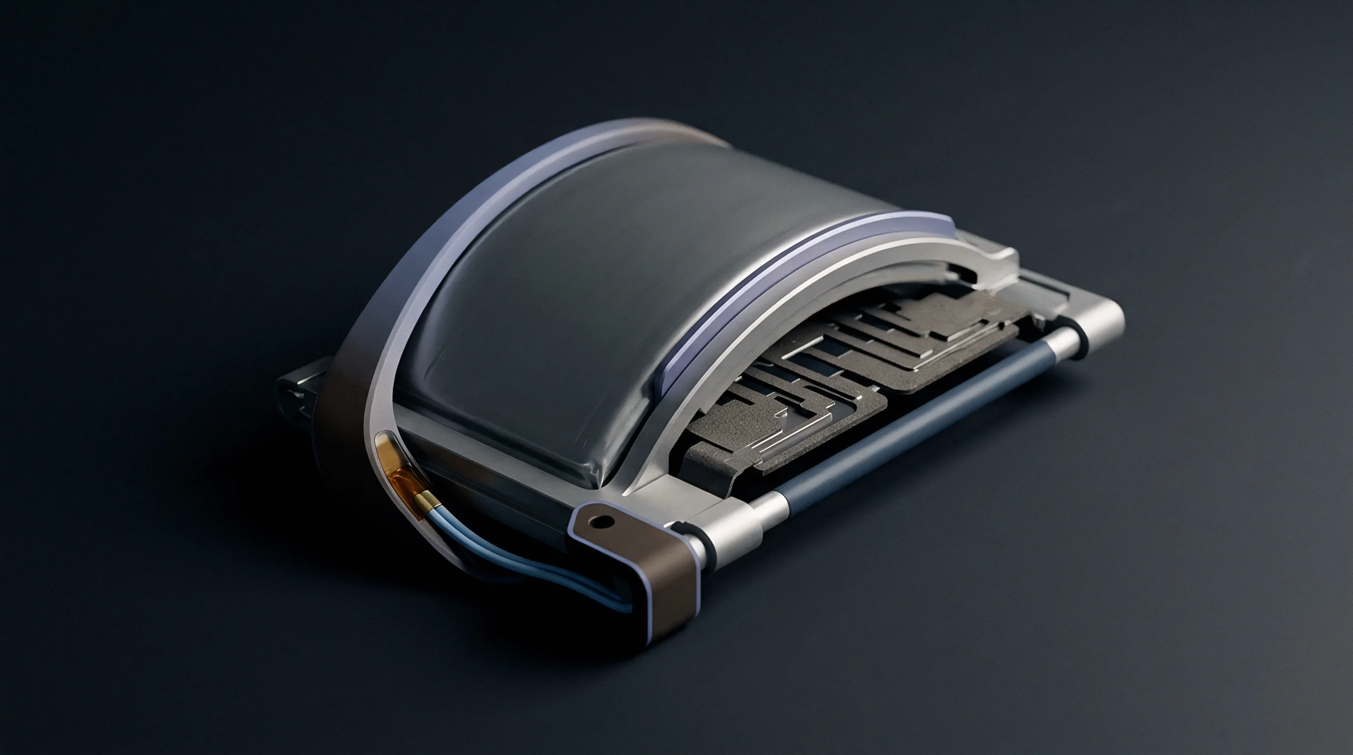
Cell pack designs rely on elastomeric foam pads positioned between adjacent pouch cells to absorb dynamic thickness variations while maintaining targeted compressive loads. Closed-cell polyurethane and silicone foams function as non-linear spring elements inside the stack array, transforming stiff mechanical boundaries into compliant spring-mass configurations. Selecting foam thickness, density, and compression-set characteristics dictates whether internal cell pressure remains within safe microscale fatigue boundaries across the operating temperature window.

Restraint Spring Dynamics and Stress Redistribution
Uncontained pouch breathing generates progressive mechanical swelling caused by both reversible lithium insertion and irreversible solid-electrolyte interphase accumulation over calendar life. As cell thickness grows by 0.40 millimeter to 1.20 millimeters over 1500 cycles, an overly stiff restraint foam drives stack stress past critical decohesion limits. Conversely, an under-compliant pad allows excessive displacement, triggering interphase shear fatigue and internal layer shifting.
Elastomeric foams compensate for cyclic growth. Non-linear force-deflection curves of microcellular elastomeric foams feature a distinct stress plateau region, where large strain changes produce small variations in normal pressure. Positioning the initial cell pre-load at the lower boundary of this compression plateau stabilizes the stack pressure profile across multi-year operational windows.
Standard EN 1604 testing confirms that closed-cell silicone cushion materials maintain over 82 percent of their initial modulus under 100,000 cyclic pressure pulses at 60 degrees Celsius, preventing premature stack pressure collapse.
Foam compression response shifts markedly under combined thermal and mechanical aging cycles. Exposure to elevated temperatures accelerates polymer chain relaxation, reducing the effective clamping pressure exerted on the pouch faces. Lower restraint stress permits micro-motion between internal anode coatings and separator separators during high-rate current pulses, accelerating local active layer exfoliation.

Compression Fixture Calibration Protocol
Accurate implementation of stack compression requires calibrating assembly equipment to account for tolerances in cell pouch thickness, foam pad thickness, and endplate deflection.
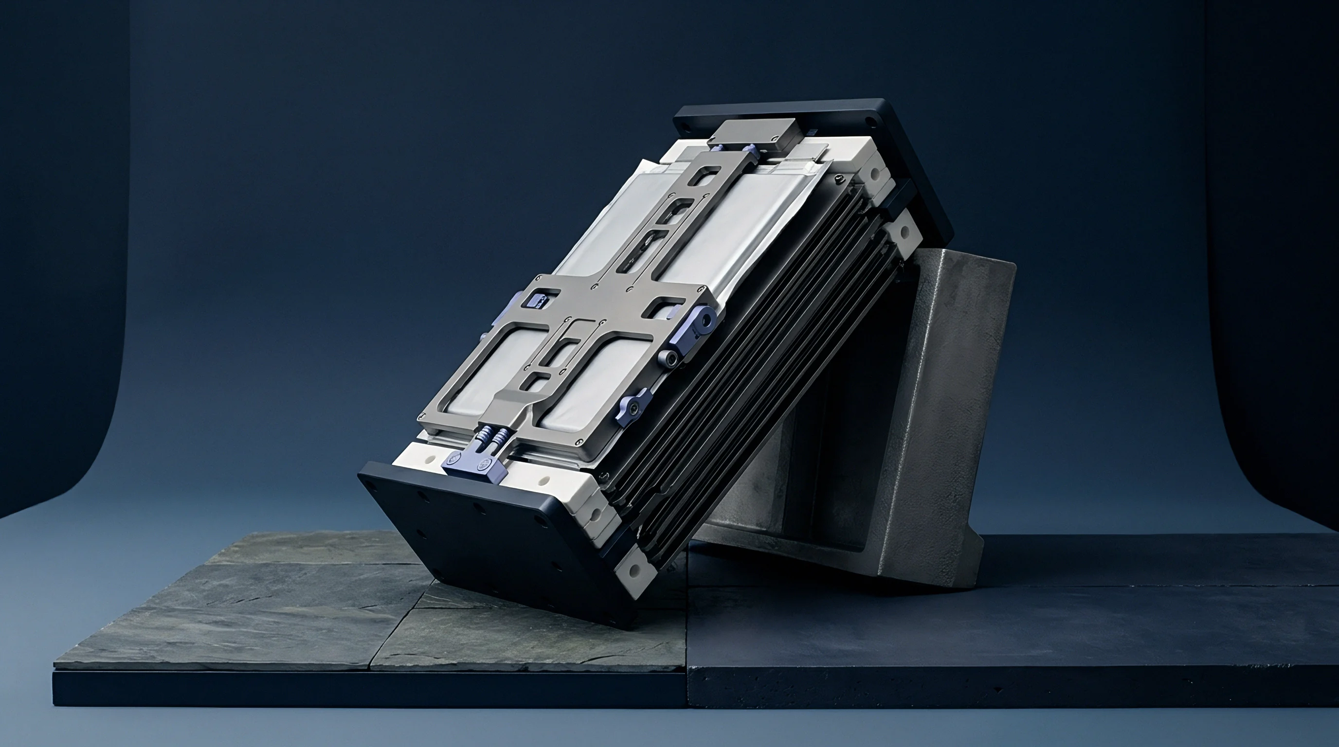
- Position the uncompressed cell stack into the rigid calibration fixture equipped with multi-axis load cells.
- Apply a uniform nominal displacement rate of 0.10 millimeter per second until reaching the baseline target seating force.
- Measure the steady-state mechanical pressure across all cell faces using calibrated tactile pressure matrix sensors.
- Adjust shim stock thickness at endplate mounting points to compensate for cumulative dimensional manufacturing variations.
- Torque tie-rod fasteners to the calculated initial tension setting using a calibrated digital torque driver.
- Execute a three-cycle pressure stabilization sweep to seat internal components prior to electrical formation testing.
Contact pressure shifts during lithiation. Designing compression systems without accounting for long-term polymer strain hardening results in stack pressure exceeding maximum interface decohesion thresholds, which leads directly to internal active coating delamination, accelerated capacity fade, and localized thermal hot-spots during high-rate operation.


Fracture
Quantifying microscale decohesion requires applying fracture mechanics principles to the heterogeneous interfaces inside the pouch cell stack. Cohesive zone modeling combined with cyclic energy release rate formulations allows engineers to predict the fatigue life of binder-particle bonds as a function of restraint pressure. The critical energy release rate Gc defines the work needed to create fresh micro-crack surface area across the coating-foil interface.

Cohesive Zone Modeling of Binder Interfaces
Interfacial shear stress distribution across an active electrode layer under stack restraint depends on particle size distribution, binder volume fraction, and current collector surface roughness. Mechanical stress concentration factors rise sharply near current collector tabs and pouch edge radius folds. At these geometry transitions, combined normal and shear stresses reach values triple the nominal surface pressure of the stack.
Interfacial debonding accelerates capacity fade. The crack growth rate per cycle da/dN across the active coating interface follows a modified Paris Law relationship driven by the cyclic energy release rate range Δ G. When the applied cyclic strain energy exceeds the fatigue threshold Δ Gth, micro-cracks propagate along the binder-copper interface during each charge-discharge cycle.
| Interface Architecture | Pre-load Pressure (MPa) | Critical Energy Release Rate Gc (J/m²) | Fatigue Threshold Delta Gth (J/m²) | Fatigue Exponent m |
|---|---|---|---|---|
| Standard Graphite / PVDF / Smooth Cu | 0.10 | 22.4 | 4.2 | 3.8 |
| Standard Graphite / PVDF / Smooth Cu | 0.50 | 31.8 | 7.6 | 3.2 |
| Silicon-Graphite / SBR-CMC / Etched Cu | 0.10 | 45.1 | 12.8 | 2.6 |
| Silicon-Graphite / SBR-CMC / Etched Cu | 0.50 | 58.6 | 18.4 | 2.1 |
| Silicon-Graphite / SBR-CMC / Etched Cu | 1.20 | 38.2 | 9.1 | 3.5 |
The tabulated mechanics metrics demonstrate that moderate mechanical pre-load enhances resistance to micro-scale fatigue by closing micro-cracks and increasing friction along debonded interfaces. Excess pressure above 1.0 Megapascal decreases the fatigue threshold due to severe binder crushing and pre-straining of the polymer matrix.

What Dynamic Pressure Bands Prevent Electrode Delamination?
Determining the optimal restraint pressure envelope involves mapping decohesion initiation boundaries against cycle life under varying dynamic compression conditions. Calculating the fatigue damage accumulation index relies on linear elastic fracture mechanics modified for viscous polymer behavior.
Shear stresses concentrate at foil edges. Consider a worked example evaluating microscale crack growth rate at a silicon-graphite anode interface under two distinct stack compression designs. Assume a composite coating with an initial interfacial flaw size a0 = 15 micrometers, subjected to cyclic strain energy release rate Δ G = 8.5 Joules per square meter during full lithiation sweeps.
Under Design A, a rigid restraint clamp maintains a high fixed stack stiffness resulting in a cyclic energy release range Δ G = 14.2 Joules per square meter, exceeding the fatigue threshold Δ Gth = 12.8 Joules per square meter for the specified SBR-CMC system. Applying the Paris Law relationship da/dN = C (Δ G)m with material constants C = 1.8 × 10⁻⁸ meters per cycle and m = 2.6, the crack growth rate reaches 1.76 × 10⁻⁵ micrometers per cycle. Over 1,000 cycles, interfacial delamination crack length extends by 17.6 micrometers, reducing local electrical contact area by 28 percent.
Under Design B, an optimized elastomeric foam spring damper absorbs volumetric swelling, restricting the cyclic energy release range to Δ G = 6.4 Joules per square meter, well below the fatigue threshold Δ Gth = 12.8 Joules per square meter. Micro-crack growth remains suppressed at negligible sub-critical propagation rates below 10-8 micrometers per cycle, preserving active layer adhesion throughout cycle life.
Unrestrained expansion induces structural delamination. The exact micro-mechanical stress state that triggers localized micro-decohesion without causing binder plastic flow under non-isothermal operating conditions remains a subject of active research.


Acoustics
Non-destructive evaluation of internal microscale fatigue decohesion in sealed pouch cells requires advanced diagnostic tools capable of sensing structural shifts through aluminum laminate packaging. Ultrasonic wave propagation and acoustic emission monitoring offer high-sensitivity inspection capabilities for tracking interface degradation in real time during accelerated life testing.
Ultrasonic Transmission Mapping and Structural Diagnostics
High-frequency ultrasonic waves passing through a multi-layer pouch cell attenuate sharply when encountering delaminated interfaces or gas-filled micro-voids. Acoustic impedance contrasts between solid current collectors, active particle coatings, and liquid electrolyte create distinctive reflection signatures. Mapping signal amplitude variations across the face of a pouch cell under load isolates internal decohesion zones long before electrical capacity drop occurs.
Acoustic sensors detect micro-yield events. Transducer arrays operating in the 2.25 Megahertz to 10 Megahertz frequency band penetrate composite stack layers with sub-millimeter spatial resolution. Areas exhibiting severe coating delamination display ultrasonic reflection coefficient increases up to 35 decibels compared to fully bonded baseline regions.
According to testing guidelines aligned with ISO 16810 non-destructive standards, ultrasonic acoustic attenuation exceeding 18 decibels across a pouch face correlates with a local active contact area reduction greater than 20 percent.
Acoustic emission tracking continuously captures transient elastic stress waves released during microscopic crack initiation and binder strand fracture. High-frequency acoustic bursts occurring during initial lithiation indicate localized micro-cracking within rigid active material agglomerates or at binder-copper interfaces.

Diagnostic Array Configuration for Stack Testing
Implementing non-destructive monitoring on active pouch test stands requires specialized sensor integration to eliminate environmental mechanical noise.
- Piezoelectric Sensors mounted directly to compression endplates capture high-frequency elastic energy emissions from micro-cracking events above 100 Kilohertz.
- Coupling Elastomer Sheets placed between transducers and pouch outer surfaces eliminate air gaps and stabilize acoustic signal transmission across variable load profiles.
- Time-of-Flight Mapping Arrays resolve spatial coordinates of internal layer separations by calculating acoustic wave propagation delay differentials.
- Continuous Wave In-Situ Scanners evaluate stack sound speed alterations caused by electrolyte redistribution and microscopic void accumulation during fast-charging phases.
Signal attenuation marks interfacial void growth. Cell manufacturers frequently argue that minor acoustic attenuation shifts during early cycling reflect harmless electrolyte wet-out adjustments rather than structural binder decohesion micro-fractures.

Warranty
Establishing commercial responsibility for cell performance failures requires precise contractual definitions governing stack restraint conditions. Cell manufacturers establish performance guarantees based strictly on defined external pressure envelopes. When pack assembly tooling or elastomeric pad selection drifts outside specified mechanical parameters, warranty coverage severs clean between cell supplier and pack integrator.

Tooling Amortization and Contract Seam Definitions
Integrating pouch cell modules into high-volume pack assemblies requires capital-intensive mechanical tooling including automated compression presses, laser welding stations, and tie-bar tensioning fixtures. Tooling non-recurring engineering costs range between 250,000 USD and 1,200,000 USD per production line depending on automation level and cycle time requirements. Deviations in tooling alignment introduce asymmetric pre-load gradients across the cell surface, accelerating local interfacial fatigue decohesion.
Thermal expansion exacerbates stress concentrations. Contractual agreements must clearly specify which party retains liability for module structural dimensional stability over time. If a pack integrator installs compression foam that degrades faster than specified creep compliance allowances, the cell manufacturer disclaims liability for subsequent capacity loss or internal short circuits.
| Responsibility Area | Responsible Entity | Governing Standard / Test Specification | Financial Risk Boundary |
|---|---|---|---|
| Initial Electrode Coating Adhesion | Cell Manufacturer | ISO 2409 / ASTM D3359 Tape Adhesion Test | Cell Lot Rejection / Replacement Cost |
| Cell Pouch Thickness Tolerances | Cell Manufacturer | IEC 61960-3 Dimensional Verification | First-Article Inspection Non-Conformance |
| Stack Restraint Tooling Precision | Pack Integrator | Internal Module Tooling Acceptance Criteria | NRE Tooling Modification Expense |
| Foam Pad Long-Term Creep Compliance | Pack Integrator / Material Vendor | ISO 3386-2 High-Temperature Compression Set | Pack Warranty Claim Coverage |
| In-Service Stack Restraint Pressure Profile | Pack Integrator | UN 38.3 / SAE J2464 Mechanical Shock & Vibration | System Field Recall Liability |
Structuring commercial purchasing documentation requires inserting explicit test parameters that tie cell lifetime metrics to verified stack restraint conditions throughout qualification and serial production.
Standard supply contracts incorporate explicit clauses stipulating that any capacity degradation claim under stack restraint conditions must present continuous pressure sensor logs confirming that external module compression stayed within 0.15 Megapascal to 0.45 Megapascal throughout the operational life of the asset.