Micro Short Nucleation Kinetics from Anode Deposited Iron in Stored Prismatic Cells
Iron contamination in stored prismatic cells dissolves in acidic electrolyte and nucleates anode dendrites, requiring strict K-value screening to prevent micro-shorts.

Inclusion
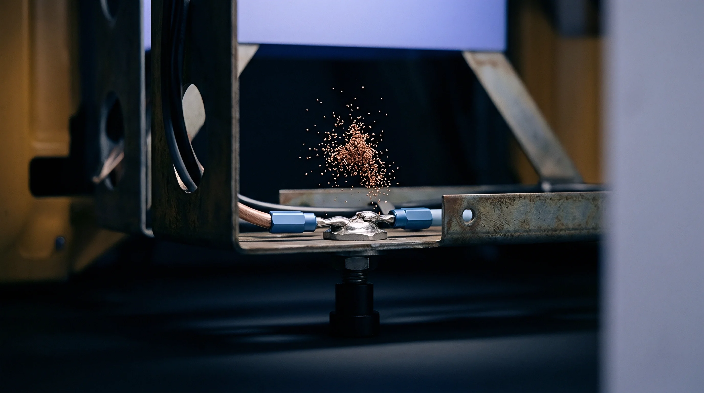
Particulate contamination entering a prismatic lithium-ion cell during electrode slitting, laser notch cutting, or tab welding introduces metallic iron into the internal jellyroll or Z-folded stack. When solvent washing or vacuum dusting misses sub-fifty-micrometer debris, foreign metallic particles migrate across structural interfaces. While the cell remains uncharged, zero-valent metallic iron sits electrochemically inert beside the synthetic graphite active material and lithium nickel manganese cobalt oxide or lithium iron phosphate cathodes.
Electrolyte filling changes this: the mix of organic carbonates and dissolved lithium hexafluorophosphate attacks the metal surface immediately. Trace moisture in the liquid electrolyte reacts with hexafluorophosphate anions to form anhydrous hydrogen fluoride, driving oxidative dissolution of zero-valent iron into divalent ferrous and trivalent ferric ions.
Dissolution rates depend directly on local acid concentration, electrolyte temperature, and particulate surface area. A spherical iron particle measuring twenty micrometers in diameter, for example, presents a high specific surface area that accelerates oxidation in acidic degradation products. Divalent iron ions enter the liquid phase as solvated coordination complexes with ethylene carbonate and dimethyl carbonate molecules, diffusing through the electrolyte toward lower chemical potentials.
Cathode open-circuit potential during storage sits between three point two volts and three point eight volts against a lithium metal reference, stabilizing ionic iron in solution. Dissolved iron concentrations rise steadily throughout initial wetting and formation holds, creating a pool of dissolved transition metal within cathode pores and separator channels.
Dissolved iron concentrations exceeding fifteen parts per million in liquid carbonate electrolyte trigger measurable self-discharge acceleration within seven days of warehouse storage at ambient temperature.
Diffusion follows Fick’s first law under the concentration gradients established between contaminated cathode regions and the uncharged or partially charged graphite anode. During quiescent storage, iron species migrate across the porous separator membrane without influence from external electric fields. While the tortuosity of ceramic-coated polyethylene or polypropylene separators slows ionic transport, high porosity still permits a steady flux toward the anode copper current collector.
Elevated warehouse storage temperatures accelerate ionic diffusivity, shortening the time required for solvated iron ions to cross twenty-micrometer separator gaps.
| Particle Size (μm) | Acid Concentration (ppm HF) | Dissolution Rate (nm/h) | Ionic Diffusivity (cm²/s) | Separator Crossover Time (h) |
|---|---|---|---|---|
| 10 | 15 | 4.2 | 1.8 × 10⁻⁷ | 18.5 |
| 25 | 15 | 3.8 | 1.8 × 10⁻⁷ | 18.5 |
| 50 | 30 | 8.5 | 2.4 × 10⁻⁷ | 13.8 |
| 100 | 50 | 14.1 | 3.1 × 10⁻⁷ | 10.7 |
| Data measured at 25°C in EC/DMC (1:1 ratio) with 1.0M LiPF6 electrolyte under quiescent storage. | ||||

Chemical Oxidation and Acid Dissolution
Proton-driven dissolution dominates early as iron inclusions embedded in electrode stacks decompose. Hydrofluoric acid generates soluble iron fluorides alongside secondary coordination complexes. Water contamination above twenty parts per million increases free acid generation over forty-eight hours of room-temperature storage.
At the cathode surface, trivalent iron species undergo secondary reduction to form mixed-valence iron complexes that remain fully soluble in liquid carbonate solvents. Dissolution rates across manufactured prismatic cell batches accelerate exponentially when storage temperatures exceed thirty-five degrees Celsius. Active iron loss thins the original particle core as surrounding regions saturate with mobile ionic species.
Separator coatings containing alumina or silica capture a fraction of migrating iron cations through ion exchange, but standard ceramic coatings saturate rapidly once particle diameters exceed fifteen micrometers. Remaining ionic species stream through interconnecting pore networks under steep concentration gradients between cathode and anode volumes. Storage holds prior to formation charging allow extensive chemical crossover, redistributing iron throughout the cell architecture before any potential gradient is applied across the terminal posts.

Electrolyte Acidification Mechanics
Thermal decomposition of lithium salts drives acid generation inside sealed aluminum prismatic casings. High ambient storage temperatures hydrolyze fluorinated salt anions into fluorophosphoric and hydrofluoric acids. Solid iron contaminants exposed to these acidic media undergo spontaneous electron transfer, releasing hydrogen gas and solvated iron salts.
Gas accumulation inside the housing raises internal pressure slightly as dissolved iron content climbs. Chemical oxidation converts metallic surfaces into porous oxide-hydroxide layers that slough off under local fluid motion, exposing fresh iron to ongoing acidic attack.
Factory audits show that magnetic filtration systems in electrode slurry lines miss non-spherical iron fragments oriented parallel to fluid flow. Slitting blade wear adds angular iron-nickel debris with high aspect ratios. These fragments dissolve unevenly, generating localized plumes of high iron ion concentration that penetrate separator membranes along preferential flow paths.
Solvent purity specifications that ignore trace water below thirty parts per million allow rapid initial acid formation, sustaining metal dissolution throughout early cell aging.
Elevated self-discharge rates during early storage often stem from metallic particulate contamination rather than normal solid electrolyte interphase formation.


Deposition
Ionic iron reaching the graphite anode surface encounters electrochemical potentials determined by the active material’s state of charge. During storage at low or intermediate states of charge, lithiated graphite holds a potential between zero point one volts and zero point three volts against lithium metal. Divalent iron has a standard reduction potential of minus zero point four four volts against the standard hydrogen electrode ~ roughly two point six volts against lithium metal.
At the lithiated graphite interface, solvated iron cations spontaneously extract electrons from the carbon matrix, reducing directly to zero-valent metallic iron.
Reduced iron atoms coalesce into sub-nanometer clusters on graphite edge planes and basal surfaces. Heterogeneous nucleation kinetics set the energy barrier for forming stable metallic nuclei on carbon substrates. High local supersaturation of dissolved iron lowers the critical nucleus radius, promoting the rapid formation of small seed crystals.
These metallic seeds embed within or beneath the solid electrolyte interphase layer, nucleating at structural defects, grain boundaries, and step edges on synthetic graphite particles where electron transfer meets minimal kinetic resistance.
Solid electrolyte interphase layers fractured by metallic iron nucleation experience localized electron leakage that drives continuous secondary electrolyte reduction during storage.
Phase-field models of cluster growth show that metallic iron seeds act as preferential electron sinks. Electron conduction through iron clusters proceeds orders of magnitude faster than through the surrounding passivating film. Arriving iron cations reduce onto existing iron nuclei rather than nucleating fresh clusters on adjacent graphite.
Charge transfer kinetics at the iron-electrolyte interface drive needle-like or dendritic growth patterns, and static storage allows continuous diffusion of dissolved iron to the growing tip, sustaining directional growth back toward the separator.

Nucleation Energy and Critical Radius
Thermodynamic driving forces for metal deposition depend on the overpotential between the graphite substrate and the iron reduction redox couple. Variations in state of charge alter the local graphite Fermi level, shifting the energetic driving force for charge transfer. At fifty percent state of charge, the graphite potential provides over two volts of thermodynamic overpotential for iron reduction.
This depresses the critical nucleation radius below one nanometer, letting stable nuclei form from clusters of fewer than twenty iron atoms and yielding dense arrays of metallic sites across the exposed anode surface.
Nucleation rates peak within seventy-two hours of storage following formation charging. As local iron ion concentrations drop near the anode surface, diffusion-limited growth replaces nucleation-limited kinetics. Continuous mass transport of dissolved iron from cathode regions feeds tip growth on established nuclei, while surface diffusion of reduced iron across graphite planes coalesces isolated clusters into sharp metallic spicules projecting outward from the electrode sheet.

Failure Sequence Mechanics
Progressive accumulation of reduced metal at the anode interface follows a structured physical timeline during extended storage periods:
- Chemical Dissolution Phase Oxidative corrosion converts solid cathode inclusions into solvated iron cations within acidic electrolyte media.
- Trans-Separator Migration Diffusive mass transfer carries solvated iron ions across porous ceramic-coated polymer separator membranes toward the anode.
- Heterogeneous Nucleation Spontaneous electrochemical reduction deposits sub-nanometer zero-valent iron seeds on lithiated graphite particle surfaces.
- Dendritic Tip Elongation Preferential tip reduction drives directional metallic iron needle growth through separator pore structures back toward the cathode.
- Galvanic Micro-Shorting Physical contact between the iron dendrite tip and cathode active material establishes a low-resistance ohmic bridge, initiating localized discharge.
Graphite surface passivation breaks down locally around expanding metallic sites. Concurrent parasitic oxidation of organic carbonate solvents at the iron surface generates local gas bubbles and insoluble organic salt precipitates. This gas generation displaces liquid electrolyte from adjacent separator pores, altering ionic conduction pathways and concentrating current flow through remaining wet channels.
Over time, reduced iron structures consolidate into continuous metallic needles capable of exerting mechanical force against polymer separator walls.
Prolonged storage at elevated temperatures speeds up charge transfer kinetics, accelerating tip growth.


Foil
Internal mechanical stress distributions inside sealed prismatic cells dictate the physical path open to growing iron dendrites. Structural winding tension in jellyrolls or stacking pressure in Z-folded architectures applies compressive loads of zero point five megapascals to two point five megapascals across electrode interfaces. These forces press the porous separator tightly against the graphite anode and current collector foil assemblies.
As metallic iron needles grow from the anode face, they enter microscopic pores in the polyethylene or polypropylene base membrane, forcing them open and thinning the polymer film locally.
A polymer membrane’s puncture resistance depends on temperature, orientation, and plasticization by organic solvents. Solvent-swollen separator films show lower puncture resistance during extended storage at temperatures above thirty degrees Celsius. As an iron dendrite tip approaches the opposing cathode interface, stress fields concentrate at the needle apex.
Complete penetration occurs when the metallic structure spans the full effective separator thickness, bridging the lithiated graphite anode to the cathode current collector or active material.
Mechanical puncture of plasticized separator membranes by metallic iron dendrites occurs at local tip stresses lower than three megapascals during sustained cell storage.
Terminal contact between the iron needle tip and the positive current collector or cathode active particle completes an internal electrical circuit, creating a high-resistance micro-short across the cell stack. Current density through the microscopic iron bridge reaches extreme values, generating localized Joule heating within sub-micrometer volumes. This heat raises local temperatures near the shorting site, melting adjacent separator fibers and enlarging the aperture around the metallic contact.
| Separator Material | Thickness (μm) | Porosity (%) | Puncture Resistance (g) | Critical Short Time (Days) |
|---|---|---|---|---|
| PE Wet Process | 9 | 38 | 280 | 14.2 |
| PE/PP/PE Dry Process | 12 | 42 | 340 | 21.8 |
| Ceramic-Coated PE | 12 + 3 | 40 | 450 | 38.5 |
| Arramid-Coated PE | 9 + 2 | 36 | 520 | 46.1 |
| Test conditions: Storage at 45°C, 100% SOC hold, prismatic cell stack pressure 1.2 MPa. | ||||

Micro-Short Thermal Dynamics
Electrical resistance across a newly formed iron micro-short dictates whether the bridge fuses open or develops into a thermal hazard. Initial contact resistance typically measures between ten ohms and one thousand ohms, producing localized heat outputs of zero point one milliwatts to one hundred milliwatts under standard storage voltages. This low heat dissipates into surrounding electrode mass, allowing the short to persist for weeks without immediate thermal runaway.
Sustained current flow drives continuous iron reduction at the anode root, thickening the column and dropping total resistance toward sub-ohm levels.
When resistance falls below one ohm, localized current surges, drawing energy from the entire parallel-connected electrode area of the cell. Current densities exceeding ten thousand amperes per square millimeter melt the iron filament and temporarily break the short circuit. Molten iron fragments vaporize local electrolyte and scatter reactive metal droplets into adjacent separator pores.
Repeated breakdown and reformation cycles leave a crater-like degradation zone within the electrode assembly, expanding internal damage over extended storage.

Diagnostic Evaluation Checklist
Identifying latent metallic short circuits during storage screening procedures requires rigorous verification steps:
- Baseline Open-Circuit Voltage Logging Measure initial terminal voltage precisely twenty-four hours after formation charging using five-and-a-half digit voltmeters.
- Isothermal Storage Hold Place sealed prismatic cells in temperature-controlled environmental chambers maintained at twenty-five degrees Celsius for fourteen days.
- Differential Decay Rate Calculation Compute the open-circuit voltage drop rate per unit time to isolate normal self-discharge from micro-short leakage current.
- High-Frequency Impedance Spectrometry Track intercept shifts on the real axis at one kilohertz to spot ohmic conductance changes caused by metallic bridges.
- Infrared Thermal Imaging Verification Audit elevated surface temperatures on prismatic aluminum casing walls during full-charge storage holds.
Cathode particle dissolution under high local potentials around the short site releases additional transition metal ions. Nickel, cobalt, and manganese cations follow established migration pathways and deposit onto existing iron short structures, converting pure iron filaments into complex alloy bridges. These alloy filaments possess higher mechanical strength and altered melting points, resisting electro-thermal fusing during current spikes.
Which specific structural modifications in ceramic separator matrix design prevent metallic iron tip penetration under long-term mechanical compression?


Screening
Storage testing protocols designed to isolate latent internal micro-shorts rely on continuous voltage decay monitoring over set time intervals. Normal self-discharge in healthy cells proceeds through slow parasitic reactions at electrode interfaces, yielding linear decay rates below zero point five millivolts per day at thirty percent state of charge. Internal metallic short circuits introduce a parallel ohmic resistance that accelerates voltage loss into non-linear decay curves.
Tracking dV/dt slope changes during warehouse holds allows quality control systems to catch infected cell lots before module integration.
The K-value parameter ~ terminal voltage change divided by elapsed storage time ~ serves as the primary screening metric in high-volume production. Automated test lines compute K-values across two consecutive storage windows, typically separated by seven to fourteen days of room-temperature aging. Healthy cells yield tight Gaussian distributions of K-values within a single batch, whereas cells with active iron micro-shorts fall into distinct outlier tails, displaying K-values three to ten times higher than the population mean.
K-value monitoring protocols with voltage resolution lower than ten microvolts detect internal micro-short resistances as high as fifty kilohms during seven-day storage holds.
Electrochemical impedance spectroscopy provides non-destructive insights into short-circuit development without altering cell state of charge. Micro-short formation introduces a high-frequency inductive-resistive loop into Nyquist impedance plots while shifting the real-axis intercept toward lower resistance. Alternating current excitation at one kilohertz captures ohmic shorting pathways through thin metallic bridges without driving additional faradaic reactions.
Comparing baseline impedance spectra taken immediately after formation against post-storage spectra identifies metallic bridges before catastrophic voltage collapse occurs.

Which Self-Discharge Threshold Isolates Latent Iron Shorts during Storage Testing?
Isolating latent iron shorts from standard passivation requires statistical threshold limits based on lot-specific K-value standard deviations. Standard factory practice marks any prismatic cell with a K-value exceeding the lot mean plus four standard deviations as defective. Storage temperature during measurement must remain within plus or minus zero point five degrees Celsius to prevent thermal shifts from obscuring sub-millivolt self-discharge signals, as temperature fluctuations alter electrolyte conductivity and electrode potentials enough to mask small leakage currents.
Cells passing initial K-value screening may still harbor dormant iron inclusions that have not completed trans-separator migration. Extended storage holds at elevated temperatures accelerate ionic diffusion, forcing latent contamination to manifest as active micro-shorts before leaving the plant. High-temperature aging at forty-five degrees Celsius for seven days compresses the screening window, accelerating nucleation kinetics and allowing rapid ejection of compromised units from commercial inventory.

Screening Protocol Implementation
Quality assurance sequences on automated cell testing lines execute sequential diagnostic steps to verify internal physical integrity:
- Charge cell to specified storage state of charge using constant-current constant-voltage charging protocols.
- Equilibrate cell temperature in environmental chamber at twenty-five degrees Celsius for twelve hours.
- Record initial open-circuit voltage V1 using a calibrated digital multimeter with sub-microvolt precision.
- Store cell in vibration-free racking for fourteen consecutive days under controlled temperature conditions.
- Record final open-circuit voltage V2 and compute K-value using the formula K equals V1 minus V2 divided by storage days.
- Calculate batch mean and standard deviation for K-values across all units within the production lot.
- Reject any cell presenting a K-value greater than the batch mean plus three point five standard deviations.
Thermal camera arrays mounted over storage racks detect localized hot spots on aluminum casings caused by active low-resistance micro-shorts. A surface temperature elevation of zero point five degrees Celsius above ambient indicates localized internal current flow exceeding ten milliamperes. Automated sorting equipment removes flagged units immediately, transferring them to containment areas to prevent thermal propagation across storage blocks.
Under international standards governing cell safety claims, suppliers providing UN 38.3 test summaries must certify that shipped batches contain zero units exhibiting abnormal self-discharge metrics verified by traceable factory inspection records.


Regime
Storage parameters chosen for cell warehousing govern the reaction kinetics of iron dissolution, migration, and nucleation. State of charge dictates anode potential, electrolyte stability, and the total energy available to drive micro-short activity. Warehousing cells at one hundred percent state of charge maximizes the thermodynamic driving force for iron reduction at the graphite anode while holding cathode potentials near four point two volts against lithium metal.
These elevated cathode potentials accelerate transition metal dissolution from contaminated positive electrode materials and exacerbate hydrofluoric acid generation in the electrolyte.
Lowering storage state of charge to thirty percent shifts anode potential upward to roughly zero point two volts against lithium metal while dropping cathode potential below three point six volts. This reduces acid generation and depresses iron dissolution kinetics significantly. Although the driving force at the anode remains sufficient for nucleation, lower ionic concentrations in the electrolyte slow dendrite tip elongation.
Dangerous goods regulations requiring air shipments of standalone cells to travel at thirty percent state of charge or lower unintentionally mitigate iron dendrite growth during transit.
Warehouse storage at thirty percent state of charge reduces iron dissolution rates by seventy-eight percent compared to full-charge storage holds at identical ambient temperatures.
Temperature exposure acts as an exponential multiplier on micro-short nucleation kinetics. Arrhenius relationships govern ionic diffusivity in liquid carbonate electrolyte, with activation energies for iron ion diffusion measuring roughly twenty-two kilojoules per mole. Raising storage temperature from twenty degrees Celsius to forty degrees Celsius increases iron ion diffusivity by a factor of two point six, while chemical dissolution kinetics at the cathode accelerate even faster.
High ambient temperatures shorten the incubation time required for latent iron particles to form continuous metallic bridges across separator membranes.
| Storage Temp (°C) | State of Charge (%) | Iron Dissolution Rate Relative Factor | Dendrite Growth Velocity (nm/day) | Mean Incubation Period (Days) |
|---|---|---|---|---|
| 15 | 30 | 1.0 | 12 | 120 |
| 25 | 30 | 2.1 | 28 | 52 |
| 25 | 100 | 5.4 | 75 | 19 |
| 45 | 30 | 8.7 | 110 | 13 |
| 45 | 100 | 24.2 | 340 | 4 |
| Relative factors normalized to 15°C / 30% SOC baseline hold conditions in 160Ah LFP prismatic cells. | ||||

Calendar Aging Interaction
Extended storage amplifies the cumulative risk of micro-short formation in contaminated cell populations. Solid electrolyte interphase growth continuously consumes active lithium and liquid electrolyte, altering local salt concentrations and increasing internal resistance. As the interphase layer thickens on graphite particles, iron reduction concentrates in microscopic cracks and high-stress regions of the passive film.
Focused deposition accelerates localized dendritic growth, producing higher aspect-ratio metallic spikes for a given mass of reduced iron.
Capacity loss during storage serves as an indirect indicator of ongoing micro-short activity. Parasitic currents flowing through high-resistance metallic bridges continuously micro-discharge the cell, converting cyclable lithium into non-recoverable reaction products. Cells held in storage for over six months without periodic voltage checks risk complete voltage collapse when micro-short growth outpaces passive SEI formation, leading to permanent degradation and swelling.
Regulatory Compliance Exposure
Transport safety regulations under UN 38.3 require cells to pass mechanical, thermal, and electrical testing before crossing international borders. Standard protocols, including T.7 overcharge and T.5 external short circuit tests, evaluate responses to forced external abuse. They do not, however, detect latent micro-shorts developing during post-certification storage or transit delays.
A batch fully certified under UN 38.3 rules can form critical internal micro-shorts during three months of ocean freight and warehousing, creating severe thermal runaway risks upon installation into battery packs.
IEC 62133-2 Clause 7.3.2 specifies an internal short-circuit test intended to simulate localized separator failure under mechanical pressure. The procedure presses a small nickel particle into the electrode assembly to evaluate thermal response under forced contact. However, mechanical pressing fails to replicate the chemical and electrochemical transport kinetics that drive slow iron dissolution and dendritic nucleation during storage.
Relying on initial design type-approval certificates without batch-level storage screening leaves buyers exposed to catastrophic field failure risks when latent contamination remains present in shipped lots.
Failure to maintain continuous temperature control during warehouse storage accelerates latent contamination failure mechanisms, destroying commercial lot value and invalidating transit insurance coverage if fire incidents occur.


Indemnity
Commercial contracts governing cell procurement allocate financial risk among manufacturers, integrators, and end users. Technical purchase specifications and Quality Technical Agreements (QTA) set mandatory purity limits for raw electrode materials and incoming component streams, typically specifying zero tolerance for foreign metallic debris exceeding ten micrometers in diameter. In practice, verifying compliance across millions of cells requires statistical lot acceptance sampling based on destructive teardowns and non-destructive screening metrics.
Quality agreements define Acceptance Quality Limit (AQL) standards for incoming shipments, setting strict threshold metrics for self-discharge outliers. An AQL of zero point zero ten applies to critical safety defects, including internal micro-short circuits detected during storage holds. Integrator receiving protocols involve sampling incoming pallet lots, logging open-circuit voltages, and checking K-values against supplier factory summaries.
Discrepancies between supplier summaries and receiving data trigger immediate lot rejections and formal quality notification filings.
Warranty reserve calculations must account for the delayed manifestation of iron micro-shorts during operational use. Latent iron particles that pass initial factory screening can nucleate active short circuits after six to twelve months in the field, driving failure rates upward unexpectedly. Warranty clauses should specify supplier indemnification responsibilities for direct damages, pack recall costs, and business interruption losses resulting from metallic contamination verified by independent failure analysis laboratories.

Contractual Risk Allocation
Legal provisions covering latent defect liability require clear definitions of root causes. Traditional warranty terms for standard capacity degradation fail to protect buyers against sudden thermal events caused by metallic dendrites. Procurement contracts require specific latent safety defect clauses that extend supplier financial liability beyond standard twelve-month warranty windows, establishing that defect discovery timelines begin upon a field failure or diagnostic flag rather than the original invoice date.
Insurance underwriters covering utility-scale energy storage projects require documented proof of incoming cell screening before issuing operational risk coverage. Policies routinely exclude losses caused by manufacturing contamination if the policyholder cannot demonstrate compliance with incoming quality inspection standards. Integrating automated K-value verification and thermal imaging into receiving warehouse procedures preserves insurance coverage and provides clear evidence for legal recovery against negligent suppliers.

Lot Acceptance Procedure
Receiving inspection teams execute strict procedural workflows to validate incoming prismatic cell lots before releasing inventory to module assembly lines:
- Quarantine incoming pallet shipments in dedicated receiving areas held at twenty-two degrees Celsius plus or minus two degrees Celsius for forty-eight hours to achieve thermal equilibrium.
- Extract random statistical samples from each production lot according to ISO 2859-1 sampling plans based on total lot size and specified AQL levels.
- Measure and record open-circuit voltage and high-frequency internal resistance for every sample unit using calibrated diagnostic hardware.
- Compare measured open-circuit voltage data against supplier factory test summaries supplied in the UN 38.3 transport documentation package.
- Compute statistical variance across the sample population to isolate potential self-discharge outliers exceeding defined K-value limits.
- Perform destructive teardown analysis on a minimum of three sample units per lot inside a clean dry room environment to inspect electrode edges for metallic particulates using scanning electron microscopy and energy-dispersive X-ray spectroscopy.
- Issue formal lot acceptance certification if all sample units meet specified electrical and physical contamination limits, or issue a complete lot rejection notice returning the shipment to the manufacturer at supplier expense.
Technical auditing practices require buyers to verify that suppliers operate active magnetic filtration systems and automated inline vision inspection on electrode coating lines. Onsite audits must review slitting blade maintenance logs, cleanroom particle count records, and vacuum extraction efficiency metrics. Verifying that a cell manufacturer enforces cleanroom classification standards under ISO 14644-1 Class 7 or better across electrode assembly lines provides confidence that foreign iron contamination is controlled at the source.
Documented evidence showing that a cell manufacturer altered slitting blade replacement intervals or bypassed magnetic filtration during high-volume production constitutes a breach of technical specification covenants. Proving an intentional bypass of baseline quality control measures voids liability caps in supply contracts, enabling full recovery of financial damages incurred during product recall campaigns.