Pouch Cell Heat Seal Micro-Void Detection and Transport Leak Resistance
Pouch cell heat seals require precise thermal pressing and non-destructive inline acoustic or helium screening to prevent micro-void leaks during transit.


Integrity
Pouch cell enclosures rely on a heat-sealed, multi-layer polymer-aluminum film to contain liquid organic electrolyte and shield internal components from moisture and oxygen. The laminate consists of an outer oriented polyamide protective layer, an aluminum alloy foil core acting as the primary barrier, and an inner cast polypropylene sealant layer. Heat sealing fuses opposing polypropylene surfaces at 180 to 220 degrees Celsius under 0.4 to 0.6 megapascals of clamping pressure for two to four seconds, establishing a polymer chain interdiffusion zone across the interface.
Flaws in the heat seal create microscopic channels and voids that undermine hermeticity. These sub-micron defects stem from solvent evaporation, non-uniform clamping temperatures, dust contamination, or thickness changes where terminal tabs break the flat seal profile. Copper and nickel tabs, coated with maleic anhydride modified polypropylene, create sharp step-height transitions as they pass into the polymer matrix.
Localized flow variations around these edges leave internal micro-cavities that can open up under mechanical or thermal stress.

Seal Morphology and Polymer Interdiffusion Mechanisms
The molecular entanglement across the inner polypropylene layer governs both the peel strength and fluid resistance of the perimeter seal. Achieving adequate chain interdiffusion requires heating above the crystalline melting point of roughly 165 degrees Celsius while applying enough pressure to purge trapped air. If interdiffusion is incomplete, an unbonded interface remains with micro-cavities scattered along the seam.
Conversely, overheating degrades the polymer, squeezes out molten resin, and thins the sealant layer, shortening the path for solvent vapor escape.
Electrolyte contact during liquid injection poses an additional hazard. Droplets of dimethyl carbonate, ethyl methyl carbonate, or ethylene carbonate on the seal flanges contaminate the polyolefin melt zone. When pressed under heat, these trapped liquids flash into vapor, forming pressurized gas pockets and channel voids across the seal width.
Cast polypropylene thermal seal fusion loses thirty percent of cohesive bond strength when electrolyte solvent contamination exceeds zero point five microliters per square centimeter prior to thermal pressing.

Electrolyte Exposure and Interface Degradation Kinetics
Internal chemical exposure gradually degrades heat seals during storage and transit. Organic carbonate solvents act as plasticizers in the cast polypropylene, swelling the matrix and lowering its glass transition temperature. Simultaneously, dissolved lithium hexafluorophosphate reacts with trace moisture to produce hydrofluoric acid and lithium fluoride.
The acid attacks the inner face of the aluminum barrier foil, causing delamination between the foil substrate and the maleic anhydride tie-layer.
| Process Variable | Optimal Operating Window | Deviation Boundary | Physical Failure Mode |
|---|---|---|---|
| Sealing Temperature | 185 to 205 °C | Below 175 °C | Incomplete polymer chain entanglement leaving unbonded channel micro-voids |
| Sealing Pressure | 0.45 to 0.55 MPa | Above 0.65 MPa | Polymer matrix squeeze-out causing foil thinning and tab edge shear voids |
| Dwell Time | 2.5 to 3.5 s | Below 1.8 s | Insufficient thermal conduction through outer polyamide layer |
| Tab Step-Height Mismatch | 0 to 5 µm variation | Above 12 µm variation | Polymer bridging failure along tab lead edge shoulders |
A major lingering question is whether micro-channels under fifty nanometers ~ which pass initial vacuum decay checks ~ expand non-linearly over time under the combined effects of solvent swelling and internal pressure during routine cycling.


Defect
Sub-micron boundary gaps in pouch cell seals exhibit complex transport behaviors driven by Knudsen diffusion and viscous Hagen-Poiseuille flow. Voids smaller than one hundred nanometers permit molecular vapor effusion, while open channels over one micrometer allow bulk liquid electrolyte migration under internal pressure, where pressure drops accelerate vapor discharge. The physical geometry of these voids determines whether a cell rapidly loses solvent mass or suffers slow, undetected air ingress over extended storage.
Liquid electrolyte leaking through open channels reacts immediately with ambient humidity. Hydrolysis of entrained salts produces hydrogen fluoride vapor, damaging nickel-plated copper tab terminals, external battery management system circuitry, and aluminum foils. Meanwhile, crystalline lithium fluoride and organophosphate solids accumulate at the void exit, partially restricting gas escape while leaving a porous path open for moisture to enter the cell.

Knudsen Flow Dynamics in Submicron Seal Channels
Molecular gas transfer through voids smaller than the mean free path of the solvent vapor follows Knudsen diffusion dynamics. Flux depends on channel radius, internal pressure, and the vapor’s molecular mass. Dimethyl carbonate, with a high vapor pressure of roughly 5.8 kilopascals at 20 degrees Celsius, evaporates preferentially over ethylene carbonate.
This steady loss of low-viscosity carbonates raises total electrolyte viscosity, degrading ionic conductivity and increasing internal resistance long before any external wetting is visible.
Pressure drops during air transit shift the pressure gradient across the seal. These altitude changes increase the driving force for vapor release through submicron defects, turning latent internal voids into active leak paths.

Acid Vapor Generation and Polymeric Degradation
Atmospheric moisture entering through perimeter voids reacts with internal lithium hexafluorophosphate. Once hydrofluoric acid levels exceed fifty parts per million, the protective passivation layer on positive current collectors begins to dissolve. The acid also attacks the maleic anhydride grafted polypropylene bond at the tabs, spreading delamination along the conductor surface and creating macroscopic leak pathways that accelerate electrolyte loss.
- Interfacial Delamination occurs when hydrofluoric acid corrodes the bond between the aluminum barrier foil and the inner polyolefin sealant layer.
- Tab Shoulder Channeling develops along the step-height transition of terminal leads due to incomplete resin flow during clamping.
- Thermal Contraction Cracking appears when rapid cooling creates internal shear stress between crystalline and amorphous polymer domains.
- Solvent Pinholes form when trapped liquid carbonate droplets flash to vapor during hot jaw closure, puncturing the semi-molten resin.
UN Manual of Tests and Criteria Section 38.3.4.2 mandates zero mass loss exceeding zero point one percent following altitude simulation testing at 11.6 kilopascals.
A wider seal perimeter with high peel strength resists long-term chemical degradation far better than a narrow seal optimized solely to maximize volumetric energy density.


Stress
Transit environments subject pouch cells to combined mechanical and environmental stresses that challenge heat seal integrity. Air freight exposes cargo holds to reduced pressures down to 11.6 kilopascals absolute, as specified in UN 38.3 protocols. This drop in external pressure produces an outward internal bias across the cell envelope, causing internal gas pockets to expand.
Thermal cycling during freight transport causes differential expansion among cell components. Polypropylene has a coefficient of thermal expansion of roughly 150 × 10-6/K, while the aluminum foil expands at about 23 × 10-6/K. Repeated temperature swings induce cyclic shear strain across the polymer-metal interface, while ambient vibration further strains brittle tab seals.

Pressure Differentials during Flight Altitude Transitions
Depressurization in cargo holds subjects sealed pouch envelopes to tensile stresses concentrated at the inner seal margin. Unrestrained cells balloon outward under internal vapor pressure, shifting flat planar stresses into localized peeling forces along the seam. Micro-voids act as stress concentrators during these deformations, driving sub-critical cracks into open channel leaks.
Restraining plates or rigid frame modules limit pouch swelling during transit. Packaging without compressive support permits unconstrained flexure that accelerates seal degradation.

Vibrational Fatigue at Terminal Tab Seal Junctions
Random mechanical vibration during truck and rail transport delivers continuous low-amplitude dynamic fatigue to the tab leads. The boundary between rigid metallic conductors and the flexible polymer film undergoes persistent micro-fretting. When vibration frequencies match the natural resonance of internal electrode stacks, mechanical loads concentrate heavily at the inner tab seal shoulder.
- Mechanical Shock Pre-Conditioning subjects test samples to three cumulative 150g half-sine shock pulses along three orthogonal axes per UN 38.3 T4 standards.
- Random Vibration Exposure applies a broadband frequency sweep from 7 Hz to 200 Hz for twelve hours under UN 38.3 T3 regulations to induce structural fatigue.
- Thermal Shock Immersion cycles units between minus 40 degrees Celsius and plus 72 degrees Celsius with maximum transition times under ten minutes under UN 38.3 T2 provisions.
- Barometric Altitude Clearance verifies zero seal rupture and zero mass loss under sustained 11.6 kPa low-pressure exposure for six hours per UN 38.3 T1 requirements.
| Transport Stress Condition | Standard Test Equivalent | Applied Load Magnitude | Seal Void Response Mechanism |
|---|---|---|---|
| Flight Cargo Depressurization | UN 38.3 T1 / IEC 62133-2 | 11.6 kPa absolute pressure for 6 h | Outward pouch swelling drives peel propagation along internal void seams |
| Thermal Shock Cycling | UN 38.3 T2 | -40 °C to +72 °C over 10 days | Differential thermal contraction cracking at metal-polymer interfaces |
| Truck Bed Random Vibration | UN 38.3 T3 / IEC 62133-2 | 7 Hz to 200 Hz sine sweep, 18 h total | Dynamic fretting fatigue at tab sealant shoulders |
| Handling Impact Drop | UN 38.3 T4 / IEC 62133-2 | 150g peak acceleration, 6 ms pulse | Instantaneous hydraulic shock of liquid electrolyte against seal edge |
Omitting rigid compressive restraints during air freight palletization allows unconstrained swelling, promoting seam peel propagation and leading to catastrophic leakage during long-haul transit.

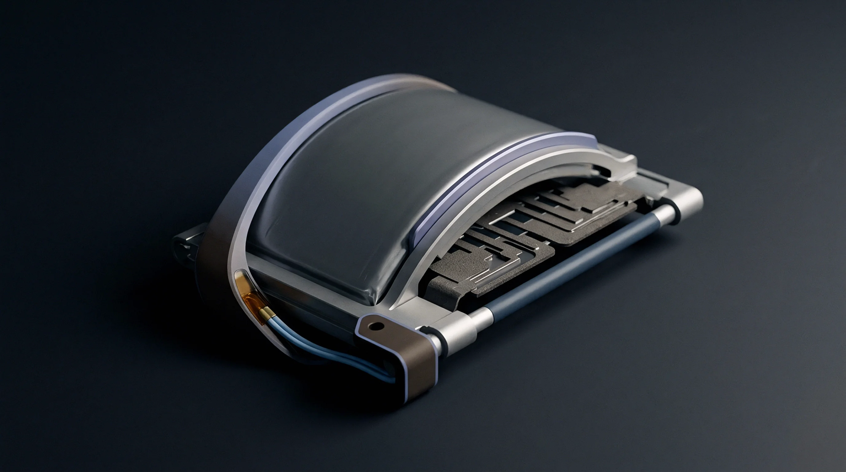
Inspection
Quality assurance on high-speed pouch cell lines requires non-destructive inline methods capable of detecting sub-micron voids prior to final sealing. Vacuum helium mass spectrometry provides exceptional sensitivity for fine defects, detecting leak rates down to 10-9 mbar·L/s as helium tracer gas flows through micro-channels. However, high equipment costs and long chamber evacuation times restrict full helium testing to offline auditing or low-volume premium manufacturing.
Inline inspection relies on optical infrared thermography, laser ultrasonics, and high-frequency acoustic microscopy, which uses acoustic reflection to pinpoint density drops. Active thermography captures heat dissipation profiles across the seam right after the jaw opens. Micro-voids and local delaminations disrupt heat conduction, showing up as distinct cold spots on calibrated infrared detector arrays.

Which Nondestructive Inspection Technique Isolates Channel Voids Reliably?
Scanning acoustic microscopy evaluates density variations across the polyolefin layer by sending ultrasonic pulses through a liquid coupling medium. High-frequency acoustic signals reflect off polymer-air boundaries inside micro-voids, mapping defects at resolutions below ten micrometers. This isolates channel voids and tab-edge gaps without altering cell structure or performance.
Optical laser displacement systems map seam thickness along the cell flange after sealing. Localized dips point to excessive resin squeeze-out, while height spikes indicate trapped debris or tab misalignment.

Acoustic Microscopy Resolution Vs Mass Spectrometry Limits
Evaluating seal integrity involves balancing measurement resolution against line cycle speed. Mass spectrometry measures total leak rates across the entire envelope but cannot locate specific micro-voids. Acoustic microscopy pinpoints exact defect coordinates along the seam, but it requires liquid coupling, complicating integration into high-speed automated lines.
- Helium Vacuum Chamber Testing detects absolute leak rates to 10-9 mbar·L/s using helium tracer gas charging prior to final degas sealing.
- High-Resolution Infrared Thermography identifies seam thermal density variations down to fifty micrometers during thermal jaw release cycles.
- Scanning Acoustic Microscopy maps interface void geometry down to five micrometers using ultrasonic wave reflection analysis.
- Air Bubble Emission Immersion identifies gross channels down to ten micrometers per ASTM D3078 submerged vacuum chamber protocols.
A seal peel strength profile exhibiting sawtooth force oscillations indicates non-uniform melt crystallization and embedded micro-void populations.
Minor seal frame thickness variations during initial commercial batch audits may reflect normal resin flow dynamics rather than active channel defects.


Protocol
Shipping compliant pouch cells demands full regulatory documentation verified under international dangerous goods rules. UN Section 38.3 testing provides the baseline for global transport approval. Shippers must present a valid Test Summary report detailing cell identification, mass, equivalent lithium content, and certified test results before carriers will accept cargo, as missing test summaries halt ocean freight.
Air transport under IATA Packing Instruction 965 requires pouch cells to ship at a state of charge no higher than thirty percent of nominal capacity without explicit written authorization from state authorities, since defective seals increase cargo risk. While shipping at a lower state of charge reduces the potential intensity of thermal runaway, it does not alter solvent evaporation rates or moisture ingress through micro-voids during extended storage.

Dangerous Goods Shipper Declarations and Safety Documentation
Carrier acceptance procedures require batch lot numbers on outer packaging to match underlying laboratory safety dossiers. The dangerous goods declaration confirms that cells have passed altitude simulation, thermal shock, vibration, mechanical shock, external short circuit, impact, overcharge, and forced discharge testing.
Failure to present verified UN 38.3 test documentation at air cargo docks results in immediate rejection and administrative quarantine of non-compliant shipments.

Quality Acceptance Limits and Warranty Liability Allocation
Commercial procurement contracts define Acceptance Quality Limit thresholds for heat seal defects using ISO 2859-1 sampling protocols. Critical defects, such as active electrolyte leaks or open tab channels, carry an AQL of zero percent, triggering immediate lot rejection and forfeiture of transport clearance upon discovery of a single failing unit.
| Regulatory Standard | Jurisdictional Authority | Mandated Integrity Criteria | Non-Compliance Enforcement Risk |
|---|---|---|---|
| UN 38.3 / PI 965 | ICAO / IATA / IMO | Zero leakage, venting, or mass loss under altitude pressure shifts | Cargo seizure, civil fines, air carrier transport bans |
| IEC 62133-2:2017 | Global Market Access | Seal mechanical integrity under high-temperature storage and vibration | Certification revocation, commercial market entry rejection |
| EU Battery Regulation 2023/1542 | European Union | Traceable durability data, carbon footprint, safe packing design | Import ban at EU port customs boundaries |
| UL 1642 Clause 13 | North America | No explosion or fire during severe physical abuse or seal failure | Product recall, commercial liability insurance voiding |
Master service agreements typically make final batch acceptance conditional on zero mass loss exceeding zero point one percent after a fourteen-day quarantine at forty degrees Celsius and ninety percent relative humidity.