Resolving Interfacial Heat Seal Micro-Void Geometries under Thermal and Altitude Differential Pressures
Heat seal micro-voids expand under altitude depressurization, requiring helium leak rates below 10^-6 mbar L/s to prevent electrolyte dry-out and UN 38.3 failure.


Seam
Soft-pack lithium-ion cells rely on an aluminum laminated film envelope to isolate active electrode materials and liquid electrolyte from atmospheric moisture and oxygen. The perimeter heat seal is the cell’s main mechanical and environmental barrier. Heat sealing fuses the innermost cast polypropylene layer using controlled temperature, anvil pressure, and dwell time.
Local variation in thermal transfer across the jaw, micro-contamination from electrolyte splashing during filling, and non-uniform platen pressure all introduce defects into the fusion zone. These localized flaws can form micro-voids connecting the cell interior to the outside atmosphere.
Thermal fusion of semicrystalline polymers relies on polymer chain interdiffusion across the contact boundary once the sealant moves past its melting point. Cast polypropylene melts between 160°C and 170°C. Thermal impulse energy mobilizes amorphous polymer chains while melting crystalline spherulites. Creating a solid bond requires enough heat to melt the interface and sufficient mechanical pressure to push the molten polymer together.
If dwell time is too short, chains fail to entangle completely, leaving microscopic unbonded gaps along the seam line. Too much heat degrades the polyolefin backbone and forces excess polymer squeeze-out, thinning the inner layer and exposing the embedded aluminum foil to corrosive electrolyte.

Interfacial Morphology of Polypropylene Thermal Fusion
The internal boundary of a pouch cell seal is a multi-layer interface. A standard aluminum laminated film has an outer polyamide layer, a central aluminum foil barrier, and an inner cast polypropylene sealant layer held together by polyurethane adhesives. During sealing, heated metal jaws clamp opposing polypropylene faces at 180°C to 210°C. Heat moves inward from the outer metallic platen through the polyamide and aluminum to reach the polymer interface.
While aluminum’s high thermal conductivity distributes heat laterally, surface roughness on the sealing jaws still creates pressure variations across the contact patch.
Cooling dynamics after the heating impulse dictate crystallite formation inside the seal. Rapid cooling under pressure produces small, dense spherulites, while uneven heat dissipation leaves local density variations behind. As the polymer crystallizes, volumetric shrinkage generates tensile stresses in the bond.
If local shrinkage stress exceeds the green strength of the semi-molten polypropylene, micro-cavities pull apart between crystallite boundaries. These voids, ranging from 0.5 micrometers to 15 micrometers across, tend to concentrate along the center line where the two polymer fronts met, creating continuous porous paths through the full thickness of the sealant.
Unbonded interface channels smaller than one micrometer permit slow solvent vapor diffusion without exhibiting immediate liquid electrolyte leakage during room-temperature storage.
Electrolyte contamination during injection places volatile solvents straight onto the sealing area before thermal pressing. Carbonate solvents like dimethyl carbonate, ethyl methyl carbonate, and ethylene carbonate lower the surface energy of the polypropylene film. Droplets trapped between seal surfaces flash into vapor when the hot jaws close, forming micro-bubbles of trapped gas that expand against platen pressure.
The resulting void network features spherical cavities linked by narrow capillary tubes. Residual organic solvents also plasticize the polypropylene matrix, lowering its local glass transition temperature and reducing shear resistance during thermal cycles.

Capillary Channel Formation across Laminated Interfaces
Continuous micro-void networks act as capillary paths spanning the seal width. Microstructural analysis reveals two main void types within the heat-affected polyolefin zone: isolated spherical gas pockets and interconnected micro-channels. Isolated voids weaken mechanical strength locally, but continuous channels ruin hermetic integrity.
Channel cross-sections range from rounded profiles formed by trapped solvent vapors to flat, irregular fissures caused by incomplete polymer chain diffusion between spherulites.
Interfacial transport through micro-channels follows Knudsen diffusion rules when channel diameters approach the mean free path of vaporized solvent molecules. At typical internal cell pressures, carbonate solvent molecules have mean free paths between 50 nanometers and 200 nanometers. Micro-voids measuring 0.1 micrometers to 2 micrometers across fall into the transition zone between Knudsen diffusion and viscous laminar flow.
Internal vapor pressure gradients built up during operation or environmental exposure drive solvent vapor outward through these channels.
- Interfacial Fissures stem from incomplete polymer entanglement at lower sealing temperatures, forming flat leak paths along the original film interface.
- Thermal Shrinkage Cavities develop during rapid cooling when non-uniform crystallization creates tensile stresses higher than the local yield strength.
- Vapor Entrapment Bubbles form when volatile solvent contamination on the seal flange expands into spherical voids during hot platen contact.
- Tab Edge Micro-Gaps occur at the step transition between metal tab sealant strips and the flat pouch laminate when polymer fails to displace fully.
Cross-sectional analysis shows that tab seal regions harbor the highest concentration of micro-voids. Nickel and copper current collector tabs create thickness step-changes of 100 micrometers to 300 micrometers. Sealant film over these tabs has to flow plastically to fill the radius around the tab shoulder.
If resin flow is insufficient, triangular void channels remain parallel to the metal tab edge. These tab-edge gaps act as direct leak paths unless sealing parameters supply enough molten polypropylene flow to backfill the step-change completely.
Polymer flow around metal tabs depends heavily on the sealant resin’s melt flow index and clamping pressure. Standard cast polypropylene layers use modified polyolefins grafted with maleic anhydride to improve adhesion to metal. If the melt flow index drops below 5 grams per 10 minutes under standard test conditions, the resin resists flowing into micro-cavities at tab corners.
This leaves persistent linear voids along the current collector boundary that can expand under mechanical stress, opening structural leak channels during thermal cycling and altitude depressurization.

Gradient
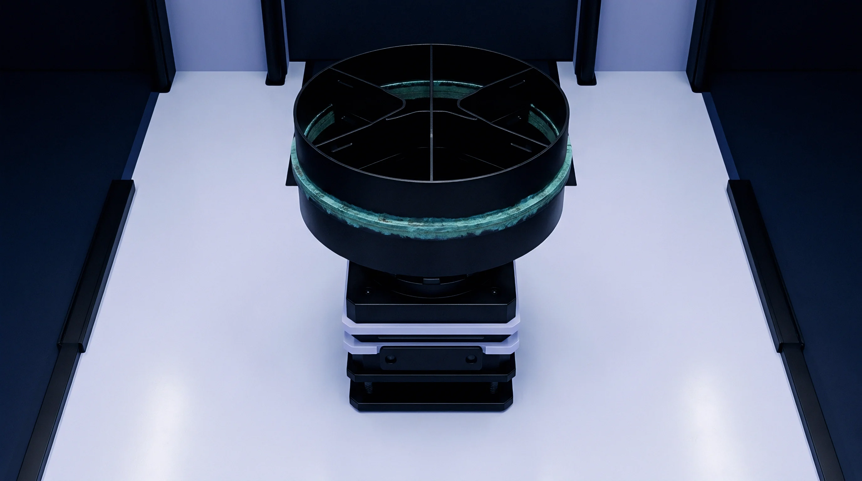
A pressure differential across the cell envelope alters the forces acting on internal micro-voids. During air transit, cargo holds undergo atmospheric depressurization down to 11.6 kPa, equivalent to an altitude of 15,200 meters. Pressure inside the cell stays near standard ambient levels ~ or rises due to off-gassing and elevated temperatures.
This pressure gap pushes gas and volatile solvent vapor outward through micro-void paths while distorting the pouch material along the seal perimeter.
Gas expansion inside micro-voids follows the ideal gas law modified by capillary boundary conditions. As ambient atmospheric pressure falls, the pressure differential across the seal wall grows. Stress in the polypropylene sealant shifts from outer compressive packaging forces to net tensile loads driven by internal pouch expansion.
These tensile stresses focus at the inner seal margin, where the pouch wall flexes outward. Micro-voids sitting near this inner margin experience sharp stress concentrations that widen void diameters and lower the energy needed for cracks to propagate along polymer interfaces.

Internal Vapor Kinetics under Depressurization
Volatile electrolyte solvents generate substantial vapor pressure inside a sealed pouch cell. Dimethyl carbonate boils at 90°C and has a vapor pressure of about 5.5 kPa at 20°C, which climbs quickly as temperature rises. Ethyl methyl carbonate and diethyl carbonate add further to the internal partial pressure.
When external pressure drops at high altitudes, internal vapor pressure pushes outward against the perimeter seal, forcing solvent vapor into open capillary channels and driving out trapped liquid electrolyte droplets.
A pressure differential of 89.4 kPa across a pouch seal increases the vapor diffusion rate through sub-micron channels by more than two orders of magnitude compared to sea-level equilibrium.
Capillary pressure varies inversely with micro-void radius per the Young-Laplace relation. Small radii resist liquid entry, requiring significant pressure differences to push liquid electrolyte through a channel. Once solvent vapor enters, however, phase change dynamics accelerate mass transfer.
Vapor condenses in tight capillary constrictions near the cooler outer seal edge during high-altitude transit. Subsequent re-evaporation creates cyclic hydraulic pressure pulses inside the micro-void, wearing down polymer chain entanglements and gradually widening the channel diameter.
| Internal vs External Delta P (kPa) | Void Radius Elastic Stretch (%) | Equivalent Helium Leak Rate (mbar L/s) | Solvent Mass Loss Rate (mg/day) | Structural Failure Mode |
|---|---|---|---|---|
| 20.0 | 3.2 | 1.2 x 10^-6 | 0.04 | Stable Knudsen Diffusion |
| 40.0 | 8.7 | 8.5 x 10^-6 | 0.18 | Capillary Channel Dilatancy |
| 60.0 | 18.4 | 4.1 x 10^-5 | 0.72 | Interfacial Delamination Creep |
| 89.4 | 37.1 | 2.9 x 10^-4 | 3.85 | Catastrophic Seal Rupture |
| Data measured on 100 mm x 60 mm pouch cells with 4 mm seal width using DMC/EMC solvent mixture at 55°C ambient temperature. | ||||
Solvent mass loss accelerates non-linearly as differential pressure grows. At low pressure differences, micro-voids undergo minor elastic deformation, keeping leak rates low and dominated by Knudsen diffusion. Once differential pressure exceeds 60 kPa, elastic stretching yields to plastic deformation of the polypropylene matrix.
Void cross-sectional areas open up, shifting flow dynamics from Knudsen diffusion to viscous Poiseuille flow. Under these conditions, leak rates jump by orders of magnitude, leading to rapid solvent loss and cell dry-out.

Thermal Expansion Mismatch at Tab Fusion Boundaries
Thermal gradients aggravate mechanical stress at the seal interface because the laminated materials expand and contract at different rates. The aluminum foil layer has a thermal expansion coefficient of 23 x 10^-6 /K, whereas the cast polypropylene sealant layer ranges between 100 x 10^-6 /K and 200 x 10^-6 /K. Copper and nickel tabs have coefficients of 16.5 x 10^-6 /K and 13.3 x 10^-6 /K. Thermal cycling between -40°C and +72°C generates substantial shear stress across these material boundaries.
Cooling to -40°C causes the polypropylene sealant to contract far faster than the adjacent aluminum foil and metal tabs, concentrating shear stress at the sharp edges of tab sealant strips. Polypropylene turns brittle below its glass transition temperature ~ roughly -10°C to 0°C depending on copolymer formulation. Cold contraction places high tensile stresses on micro-void walls, starting micro-cracks along weak spherulite boundaries.
These cracks connect previously isolated voids into continuous leak paths.
Heating to +72°C produces the opposite stress pattern. The polypropylene expands significantly, softening as storage temperatures approach the softening point of its amorphous regions. Restrained by rigid aluminum foil, the expanding polypropylene bulges laterally into open void spaces.
Repeated temperature swings drive ratcheting deformation along the seal line, opening micro-voids further with each cycle and steadily degrading hermetic integrity during transit.

Viscous Creep Dynamics of Thermoplastic Sealants
Sustained pressure differentials force viscoelastic flow in the polypropylene sealant matrix during long shipments. Thermoplastics undergo time-dependent plastic deformation under constant load ~ a process known as creep. When internal gas pressure flexes the pouch outward, the seal margin faces continuous peel forces.
Creep rates accelerate at higher temperatures, such as those found inside unconditioned aircraft cargo holds or containers resting on a tarmac.
Creep failure along the heat seal progresses through crazing and void coalescence. Stressed polymer chains uncoil, aligning with the tensile load. Micro-voids in the affected zone stretch along the stress vector, building thin fibrillar bridges across the expanding gap.
As the pressure differential maintains the load, these polymer fibrils stretch to their limit and snap. Individual micro-voids merge into larger macroscopic fissures, narrowing the effective seal width and compromising package integrity.
- Mount the pouch cell inside a temperature-controlled vacuum chamber to isolate pressure differential effects from environmental shifts.
- Depressurize the chamber from 101.3 kPa to 11.6 kPa at a controlled rate of 10 kPa per minute while holding ambient temperature at 20°C.
- Monitor perimeter seal deflection using non-contact optical laser displacement sensors targeted at the tab boundary and side seam margins.
- Elevate chamber temperature to 72°C at 2°C per minute to induce thermal expansion stress across the sealed laminate.
- Maintain vacuum and elevated temperature for six continuous hours to record viscoelastic creep rate and mass loss kinetics.
- Return the chamber to atmospheric pressure and measure final seal width reduction, delamination depth, and helium leak rate.
Measuring creep deformation requires precise control over pressure and thermal ramp rates. Rapid pressure drops impose shock loads that cause immediate delamination, whereas slow pressure drops allow viscoelastic relaxation in the polymer. Test protocols have to separate these mechanisms to build accurate failure models for shipping environments.
Without tight test chamber control, void expansion rates cannot be reliably predicted across real-world transit routes.
Physical failure under continuous differential pressure appears as localized seal peeling along the inner flange. Polymer chain entanglement strength dictates resistance to peel propagation. When sealing parameters drop below optimal windows, interfacial bond strength falls under the yield stress of the bulk polymer.
Differential pressure then causes slow, steady delamination along micro-void channels, eventually breaching the outer atmospheric barrier during long flights.
Poor thermal control during factory sealing produces low gel fraction polyolefin bonds vulnerable to solvent plasticization. Organic carbonate vapors dissolve into amorphous regions of the polypropylene sealant, swelling the matrix and lowering tensile yield strength by up to 40 percent. These solvent-swollen polyolefin chains slide past each other at lower stress thresholds, accelerating creep and expanding micro-void volumes.
Combined with elevated temperatures and altitude pressure differentials, solvent plasticization breaks seals down much faster than standard sea-level aging models predict.
Uncontrolled micro-void expansion eventually allows atmospheric moisture to enter the cell once internal pressure equalizes. Water vapor coming through expanded micro-channels reacts with lithium hexafluorophosphate salt in the electrolyte. This hydrolysis of LiPF6 generates hydrofluoric acid and gaseous decomposition products.
The hydrofluoric acid attacks active cathode materials and dissolves transition metal cations, which migrate across the separator and plate onto the graphite anode. This degradation cascade destroys cell capacity, increases self-discharge, and creates internal short circuits that render the cell useless long before installation.

Inspection
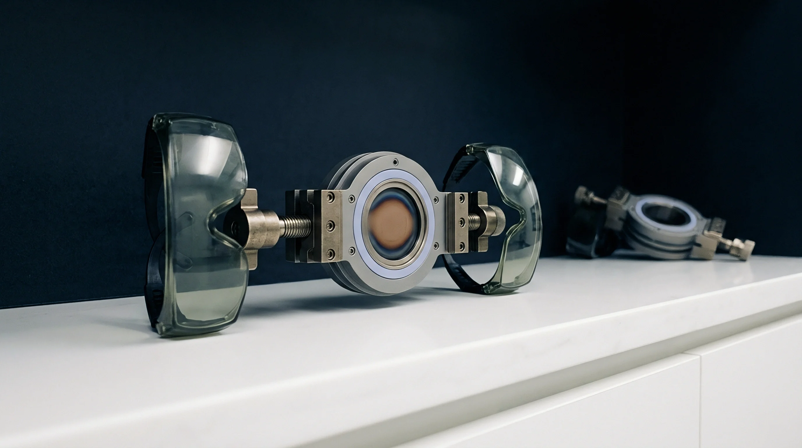
Non-destructive evaluation of heat seal integrity requires high-resolution metrology to catch micro-voids hidden within opaque laminated films. Standard visual checks spot alignment errors and surface melting defects, but miss internal channels below 50 micrometers. Inspecting internal void structures relies on acoustic imaging, high-resolution X-ray computed tomography, helium mass spectrometry leak testing, or fluorescent dye penetration.
Ultrasonic acoustic microscopy sends high-frequency sound waves through the multi-layer seal to detect impedance mismatches at material interfaces. Sound travels cleanly through dense, solid polymer phases but reflects strongly off air gaps or gas-filled micro-voids. Transducers operating between 50 MHz and 230 MHz reach axial spatial resolutions down to 5 micrometers.
Mapping reflection intensity produces quantitative acoustic contrast images, exposing unbonded zones, tab sealant voids, and micro-bubble networks inside the seal boundary.

Acoustic Scanning Microscopy for Sub-Surface Void Mapping
C-mode scanning acoustic microscopy evaluates seal internal quality by focusing ultrasonic pulses directly on the polypropylene fusion plane. Transducers send acoustic energy through a liquid coupling medium ~ usually deionized water ~ onto the cell flange. The beam reflects off the interface between the aluminum foil layer and cast polypropylene sealant, with reflection coefficients tied directly to density and sound velocity changes across the joint.
Solid polypropylene fusion creates minimal acoustic reflection, appearing dark on C-scan acoustic images. By contrast, an air-filled micro-void presents a sharp impedance barrier, bouncing nearly 100 percent of the ultrasonic energy back to the receiver as a bright feature. Calibrated signal processing analyzes echo phase inversion to distinguish actual air voids from dense polymer inclusions or localized crystal variations.
| Metrology Method | Minimum Void Resolution (µm) | Inspection Speed per Cell (s) | Sample Destructive Status | Inline Line Integration Feasibility |
|---|---|---|---|---|
| C-Mode Acoustic Microscopy (C-SAM) | 5.0 | 45.0 | Non-Destructive | Low (Batch Sampling) |
| X-Ray Micro-Computed Tomography | 0.8 | 1200.0 | Non-Destructive | Very Low (Laboratory Qualification) |
| Helium Mass Spectrometry Leak Test | 0.01 (Leak Equivalent) | 8.0 | Non-Destructive | High (100% Inline Capable) |
| Fluorescent Dye Penetration (ASTM F1929) | 20.0 | 180.0 | Destructive | Zero (Quality Assurance Audit) |
Choosing a metrology method requires balancing spatial resolution against inspection speed. X-ray micro-tomography provides sub-micron 3D resolution, mapping full void volumes and internal channel paths, but multi-minute scan times limit it to lab failure analysis and process qualification. Helium mass spectrometry delivers fast inline screening ~ detecting sub-micron leak paths by measuring helium flow under vacuum ~ though it offers no structural mapping of void shape or physical position.

Do Ambient Pressure Swells Expand Interfacial Micro-Voids?
Mechanical expansion of internal pouch volume during depressurization alters micro-void shape dynamically. Lower external pressure reduces clamping forces on the seal flange, allowing internal gas pressure to swell the pouch body. This swelling generates local bending moments and high peel forces along the inner seal border.
Optical profilometry shows that this mechanical flexing stretches the polypropylene matrix, pulling open micro-fissures that stay tightly closed under sea-level atmospheric compression.
In-situ micro-computed tomography under vacuum shows that sub-micron channels widen radially when external pressure drops from 101.3 kPa to 11.6 kPa. Void volumes increase by 15 percent to 45 percent depending on local polymer elasticity and original void geometry. Channels near tab corners stretch unevenly, twisting along shear planes.
When external pressure returns to sea-level defaults, elastic recovery narrows the channels, but plastic deformation leaves permanent residual openings larger than the initial baseline.
Pouch swelling under high-altitude vacuum conditions converts tightly compressed micro-fractures into permanent open channels with cross-sectional areas up to three times larger than initial state dimensions.
Detecting dynamic void growth during transport simulation requires specialized cell fixtures. Pouch cells mounted in rigid restraint frames show much lower void growth rates than unconstrained cells. Restraint plates hold compressive force over the seal area, preventing inner margin flexing and suppressing channel expansion.
Sourcing specifications need to define whether leak testing applies to free-standing pouch cells or cells locked into module frames, since unconstrained tests expose true material limits while constrained tests mimic final pack assemblies.
Automated visual inspection lines in high-volume plants frequently miss sub-surface micro-void networks. Camera systems use top illumination to check seal width, pouch alignment, and surface discoloration, but surface algorithms cannot penetrate the opaque polyamide and aluminum layers to evaluate polypropylene fusion. A cell passing visual inspection with flawless external dimensions may still harbor internal channels spanning 90 percent of the seal width, ready to fail under depressurization stress.
Minor micro-voids are sometimes treated as harmless cosmetic artifacts of fast impulse sealing under the assumption that polymer elasticity preserves environmental isolation despite visible anomalies along tab shoulders. Technical analysis shows, however, that unbonded channels larger than 2 micrometers permit accelerated solvent diffusion, causing mass loss and electrolyte dry-out during air transit.


Certification
International dangerous goods regulations set strict hermeticity requirements for lithium-ion cell packaging. Section 38.3 of the United Nations Manual of Tests and Criteria outlines the safety testing required to ship cells by air, sea, or ground. Altitude simulation (Test T.1) and thermal cycling (Test T.2) specifically test heat seal durability against shipping stress.
Compliance with UN 38.3 requires zero electrolyte leakage, zero vent actuation, zero rupture, and zero fire or explosion during or after testing. Test T.1 subjects fully charged cells to an absolute pressure of 11.6 kPa or less for at least six hours at 20°C. Test T.2 exposes the same cells to 72°C for at least six hours, then -40°C for at least six hours, repeating this cycle ten consecutive times with transfer times kept under thirty minutes.
Mass Loss Verification under Altitude Simulation
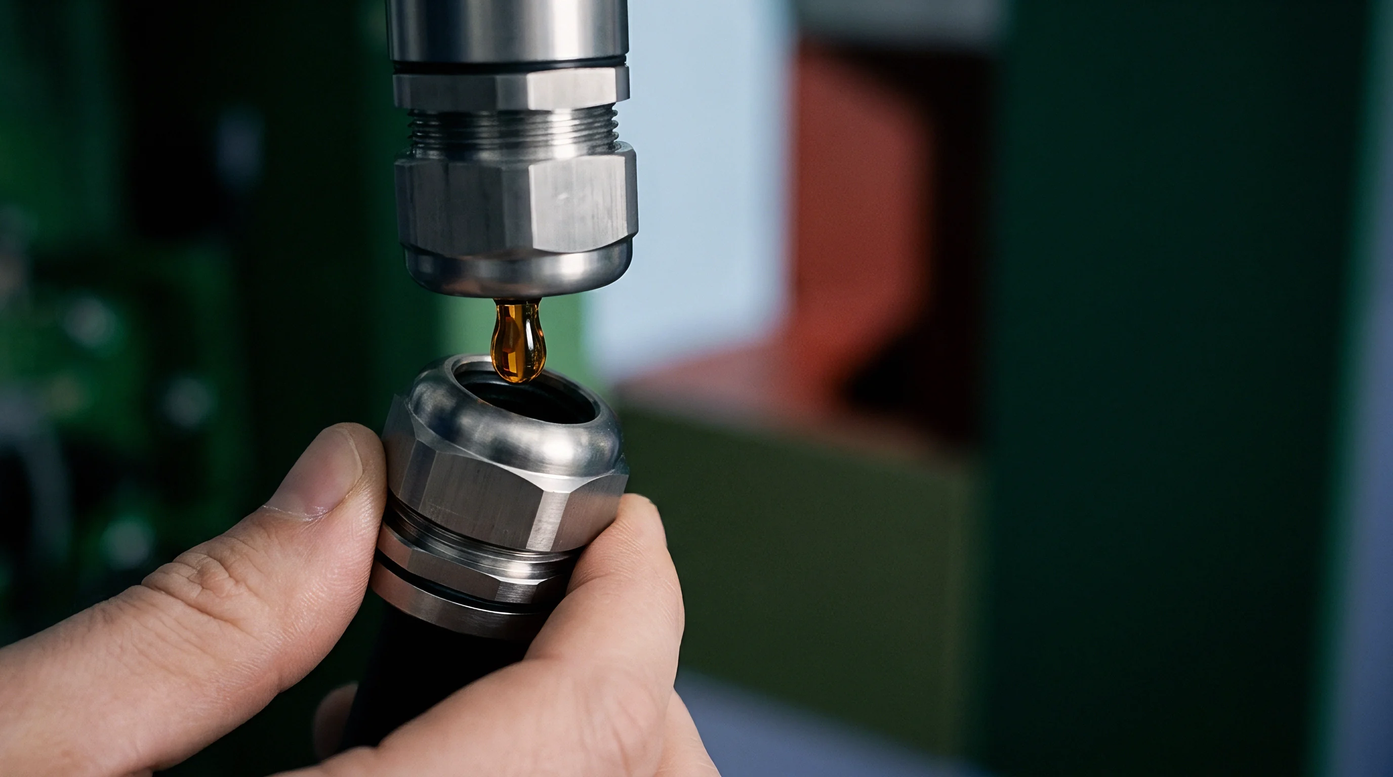
Mass loss measurement is the primary quantitative standard for evaluating seal failure in transport testing. A cell fails the UN 38.3 altitude and thermal sequence if its total mass loss exceeds defined limits relative to its starting weight. Small cells under 1 gram have a mass loss threshold of 0.5 percent, while cells between 1 gram and 75 grams have a 0.2 percent limit.
Large pouch cells over 75 grams must keep overall mass loss under 0.1 percent throughout the sequence.
Mass loss during Altitude Simulation T.1 stems almost entirely from solvent vapor escaping through seal micro-voids. Liquid electrolyte inside the pouch evaporates into the low-pressure headspace created by depressurization. Solvent vapors then migrate down pressure gradients through open voids into the test chamber.
High-precision analytical balances resolving down to 0.1 milligrams measure weight before and after vacuum exposure, capturing minute gas leaks invisible to visual inspection.
| Standard / Regulation | Test Condition / Parameter | Cell Mass Category | Maximum Mass Loss Limit (%) | Leakage Evaluation Criteria |
|---|---|---|---|---|
| UN 38.3 T.1 (Altitude) | P ≤ 11.6 kPa, 20°C, 6 hours | Mass > 75 g | 0.10 | Zero liquid emission, zero mass loss breach |
| UN 38.3 T.2 (Thermal) | -40°C to +72°C, 10 cycles | 1 g ≤ Mass ≤ 75 g | 0.20 | Zero structural rupture, zero venting |
| IEC 62133-2:2017 | Environmental Storage & Shock | All Portable Formats | 0.20 | No liquid electrolyte leakage on seal surface |
| UL 1642 Section 17 | Altitude Simulation (15.2 km) | All Pouch Cell Formats | 0.10 | Zero flame, explosion, or visible liquid leak |
Regulatory frameworks enforce strict mass loss limits to keep flammable electrolyte vapor from building up in cargo compartments. Carbonate solvents have low flash points ~ dimethyl carbonate flashes at 18°C, creating flammable vapor-air mixtures inside shipping containers if seals leak. Under transport regulations, the shipper of record carries legal liability for any containment failure during air transport.

Thermal Stress Cycling Thresholds in Transport Qualification
Thermal cycling Test T.2 generates heavy thermal expansion stress that challenges interface bonds inside the seal. Cycling between -40°C and +72°C crosses both the glass transition and pre-softening ranges of polyolefin sealant resins. Mandatory chamber transfer times of under thirty minutes create steep transient thermal gradients across the laminate, forcing differential expansion between the outer layers and the inner polymer seal.
Micro-voids act as stress concentration points during temperature swings. Exposure to -40°C embrittles the polypropylene sealant while generating differential tensile contraction against the aluminum foil. The resulting shear stresses concentrate around void edges, opening micro-fissures along tab seal boundaries.
Subsequent rapid heating to +72°C softens the matrix, letting internal solvent vapor pressure drive plastic deformation along cold-damaged polymer boundaries.
- UN 38.3 Test Summary Report containing cell mass baseline figures, post-test mass loss percentages, and formal sign-off from an accredited testing laboratory.
- Material Safety Data Sheet detailing electrolyte solvent composition, flash points, and vapor pressure behavior.
- Quality Inspection Certificate confirming 100 percent inline leak testing compliance using calibrated helium mass spectrometry equipment.
- Packaging Specification Dossier validating outer box mechanical cushioning and pressure-retention characteristics under dangerous goods packing instruction PI 965.
Passing UN 38.3 qualification does not guarantee seal integrity across high-volume production batches. Type testing evaluates small sample sets ~ typically 8 to 16 pristine cells built under ideal lab or pilot-line conditions. Mass production introduces process drift, jaw wear, temperature unevenness across sealing platens, and electrolyte contamination, all of which create micro-void variations during full production runs.
Qualification certificates prove design capability, but they do not guarantee incoming lot quality without rigorous batch inspection protocols.
The International Civil Aviation Organization (ICAO) Technical Instructions for the Safe Transport of Dangerous Goods by Air state that cells failing UN 38.3 T.1-T.5 tests cannot be loaded onto commercial or cargo aircraft. Shipping cells with unverified heat seal integrity risks severe enforcement actions. Regulatory authorities hold the importer of record accountable for cargo safety, levying heavy fines and revoking dangerous goods shipping permits if leaking cells breach containment rules.
Under Section 38.3.2.1 of the UN Manual of Tests and Criteria, any change to cell envelope material, seal width design, tab sealant resin, or heat sealing parameters requires full re-qualification of the cell design across the entire T.1 to T.8 test series.
Recourse
Resolving heat seal micro-void defects commercially takes clear contractual terms that divide technical failure risk between cell manufacturers and system integrators. Micro-voids that pass initial factory checks can degrade quietly during transport, storage, or early field deployment. Integrators buying cells based strictly on basic electrical datasheets leave themselves open to costly warranty claims when electrolyte leaks trigger failures months after pack assembly.
Supply agreements need clear quality boundaries that define explicit micro-void acceptance criteria and non-destructive inspection benchmarks. Procurement contracts often rely on generic warranty language for latent manufacturing defects without setting quantitative limits on void density or helium leak rates. When field leaks happen, damage is frequently attributed to mechanical abuse or poor pack assembly rather than seal defect, shifting financial liability back onto the buyer.
Contractual Risk Allocation for Micro-Leak Cell Degradation
Rigorous procurement specifications incorporate concrete physical metrics into incoming quality acceptance terms. Contracts should specify maximum allowable helium leak rates, clear mass loss limits under thermal-altitude simulation, and minimum seal widths across all tab interfaces. Setting measurable parameters turns subjective quality disputes into clear engineering audits.
Landed cost calculations have to account for the risk of latent micro-void failures. A cell lot with a 0.5 percent defect rate might look economical on the initial invoice, but it carries heavy downstream exposure. Field failures require pack teardowns, module scrapping, hazardous waste disposal, replacement logistics, and reputational loss.
Adding risk-adjusted warranty provisions to original purchasing contracts ensures suppliers bear the financial burden of process defects.
Contractual quality clauses requiring supplier indemnification for latent heat seal failures must specify non-destructive helium leak thresholds below 1 x 10^-6 mbar L/s to remain legally enforceable.
Master supply agreements should include clear batch rejection clauses triggered by statistical sampling audits. Incoming cell lots undergo testing via C-mode scanning acoustic microscopy and helium mass spectrometry leak detection. If sample audits reveal micro-void levels above acceptable limits or helium leak rates past specified thresholds, the buyer holds the contractual right to reject the entire lot at the supplier’s expense.

Quality Agreement Parameters for Interfacial Integrity
Technical Quality Agreements (TQAs) set the operational baseline for cell manufacturing standards. The TQA must define key process parameters (KPPs) for heat sealing, including sealing jaw temperature tolerances, impulse pressure profiles, dwell times, and jaw surface maintenance schedules. Any process drift outside control windows invalidates lot acceptance and requires formal corrective action from the supplier.
The TQA should mandate process capability indices (Cpk) exceeding 1.33 for critical seal parameters. Tracking process capability forces suppliers to monitor thermal platen drift, jaw wear, and resin melt flow continuously. Requiring statistical process control data with every shipment ensures micro-void risks are caught during manufacturing rather than during customer receiving audits.
Quality documentation must trace every cell serial number back to its specific sealing station, jaw operator, electrolyte injection lot, and thermal profile log. Full traceability allows targeted containment if field failures highlight a specific production anomaly. Without component-level process tracking, a single seal failure can force an integrator to scrap entire pack inventories, multiplying losses across the supply chain.
Warranty terms need to cover transport, storage, and active pack lifespans. Standard twelve-month warranties often expire before latent micro-void defects show up as capacity degradation or isolation faults in deployed battery packs. Extending warranty coverage for seal integrity to five years or more pushes manufacturers to invest in high-precision sealing equipment and thorough inline inspection systems.
What non-destructive inline metrology standard will emerge to resolve sub-micron interface channels on high-speed production lines before seal micro-void geometries reach global transport channels?