Thermal Runaway Heat Flux Limits in Grid Energy Enclosures
Grid battery enclosures require passive inter-cell thermal barriers to limit conductive heat flux below 120 kW/m² and contain thermal runaway propagation.


Plume
Thermal runaway in grid-scale cells converts stored chemical energy into rapid thermal and mechanical release. Once an internal short or structural fault starts exothermic breakdown in a large lithium iron phosphate or nickel manganese cobalt cell, heat moves through several competing paths: conduction across cell walls, gas venting from pressure relief valves, and radiation from incandescent particulate matter. Pinning down peak energy output requires tracking these channels simultaneously under actual pack constraints rather than relying on unconstrained bench runs.

Gas Vent Kinetics and Kinetic Heat Speeds
Primary discharge from a compromised 280Ah or 306Ah prismatic cell reaches between 600 degrees Celsius and 950 degrees Celsius within hundreds of milliseconds of rupture disk activation. Volumetric flow rates surge to between 80 liters per minute and 350 liters per minute per cell, governed by the state of charge and cycling history. This effluent carries vaporized organic carbonates, carbon monoxide, hydrogen, and aerosolized cathode particulates that burn on contact with ambient air, pushing the heat load on surrounding equipment well past what conduction through cell walls delivers on its own.
Mechanical design dictates where this energy goes. Cylindrical cells vent axially through their headers, while large prismatic formats generate broad planar jets that strike neighboring cell casings or enclosure bulkheads directly. Infrared imaging shows that convection and radiation from burning vent plumes account for 35 percent to 50 percent of the total heat transferred to neighboring structures in tight rack arrangements.
| Cell Format and Chemistry | Nominal Capacity (Ah) | Peak Conductive Heat Flux (kW/m²) | Peak Vent Gas Temperature (°C) | Gas Generation Volume (L/Ah) |
|---|---|---|---|---|
| LFP Prismatic | 280 | 120 – 145 | 650 – 780 | 1.2 – 1.6 |
| LFP Prismatic | 306 | 135 – 160 | 680 – 820 | 1.3 – 1.7 |
| LFP Prismatic | 530 | 180 – 220 | 720 – 890 | 1.5 – 2.0 |
| NMC Cylindrical (21700) | 5.0 | 250 – 310 | 850 – 1050 | 2.1 – 2.8 |
| NMC Prismatic | 180 | 290 – 360 | 900 – 1150 | 2.4 – 3.1 |

Cell Energy Partition during Thermal Runaway
Total heat output during thermal runaway splits among sensible heating of the cell core, conductive flux through the casing, and energy carried away by vented gases. Calorimetry places the total energy yield of a 280Ah LFP cell between 1.1 megajoules and 1.8 megajoules. An equivalent NMC cell produces between 2.8 megajoules and 4.2 megajoules, driven by the lower decomposition temperature of nickel-rich cathodes and the release of oxygen as the crystal lattice collapses.
A 306Ah LFP prismatic cell releases peak conductive heat flux of 140 kW/m² across its broad face during thermal runaway at 100 percent state of charge.
Conduction across broad cell faces is the main driver of immediate cell-to-cell propagation. Heat flux density through a side wall during peak runaway routinely tops 120 kilowatts per square meter, driving an uninsulated neighbor past its self-heating threshold in fifteen to forty seconds. Standard module cooling loops and heat sinks cannot dissipate a thermal transient of this scale, which makes dedicated inter-cell insulation the only practical safeguard against rack-level runaway.
Bench testing can overestimate convective heat transfer by enclosing cells in narrow test fixtures, though real rack enclosures restrict air movement just as severely.


Shield
Inter-cell barriers are the front line against cascade failures in grid battery modules. Material selection balances thermal conductivity, mechanical durability under compression, dielectric standoff, and thickness within the pack. Any barrier placed between cells must keep conductive heat transfer below the threshold for self-sustaining reaction in adjacent units, even after sustaining static preload over ten or fifteen years of field operation.

Passive Thermal Insulation Properties across Temperature Ranges
Silica aerogel composites, phlogopite mica, ceramic fiber paper, and phase-change matrices form the core options for module isolation. Nanoporous silica aerogels deliver thermal conductivities below 0.020 Watts per meter-Kelvin at room temperature and stay below 0.045 Watts per meter-Kelvin past 600 degrees Celsius. Muscovite and phlogopite mica endure temperatures up to 1000 degrees Celsius and provide electrical isolation exceeding 15 kilovolts per millimeter, but higher baseline conductivities between 0.15 to 0.50 Watts per meter-Kelvin require thicker sheets to achieve comparable insulation.
Phase-change composites pair sensible insulation with latent enthalpy sinks. Hydrated or organic endothermic matrices absorb substantial energy during phase transitions, pinning interface temperatures below 180 degrees Celsius through the initial stage of cell breakdown. Once that latent capacity is exhausted, the residual carrier matrix has to function purely as an insulator against continuing heat flux from reacting active material.
- Binder degradation at high temperature burns out organic binders within aerogel mats, leaving unsupported pockets that raise local thermal conductivity above specification.
- Compression set under stack pressure thins the insulation over years of cycling, eroding the thermal margin separating adjacent prismatic cells.
- Edge tear under lateral shear allows escaping vent flames to bypass the barrier and strike neighboring cell casings directly.
- Moisture absorption in humid environments degrades surface resistivity, raising the likelihood of dielectric breakdown as cells swell against the chassis.
Aerogel and Mica Mechanical Behavior under Compression
Module clamping hardware maintains continuous compressive force across cell stacks to restrain expansion over cyclic operation. Beginning-of-life prismatic cells sit under assembly pressures around 0.1 to 0.3 megapascals, but solid-electrolyte interphase growth and electrode gassing push internal stack pressure up to 1.0 to 1.5 megapascals over calendar life.
| Material Class | Density (kg/m³) | Thermal Conductivity at 25°C (W/m·K) | Thermal Conductivity at 600°C (W/m·K) | Max Continuous Temperature (°C) | Dielectric Strength (kV/mm) |
|---|---|---|---|---|---|
| Silica Aerogel Mat | 180 – 240 | 0.016 – 0.022 | 0.038 – 0.048 | 650 | 12 – 18 |
| Phlogopite Mica Sheet | 2100 – 2400 | 0.20 – 0.35 | 0.30 – 0.50 | 1000 | 20 – 25 |
| Ceramic Fiber Paper | 200 – 300 | 0.050 – 0.070 | 0.12 – 0.18 | 1260 | 5 – 8 |
| Silicone PCM Matrix | 900 – 1200 | 0.25 – 0.40 | 0.10 – 0.15 | 300 | 15 – 20 |
Aerogel insulation undergoes notable permanent compaction under sustained pressure, collapsing nanopores and increasing bulk thermal conductivity by 15 percent to 35 percent over service life. Rigid mica sheets experience almost no compression set, preserving dimensions and dielectric properties under high structural loads, but offer no compliance to cushion swelling cell faces.
Inter-cell compression forces alter thermal conduction paths as pouch and prismatic cells swell over calendar life.
Laminating aerogel mats to thin mica sheets balances mechanical compliance with thermal protection. The compressible aerogel absorbs dimensional changes during regular charge cycles, while the mica backing blocks localized burn-through and prevents electrical arcing if cell casings rupture or melt.
Increasing barrier thickness slows heat transfer across the module, but the penalty comes directly out of container energy density and total rack weight.


Cascade
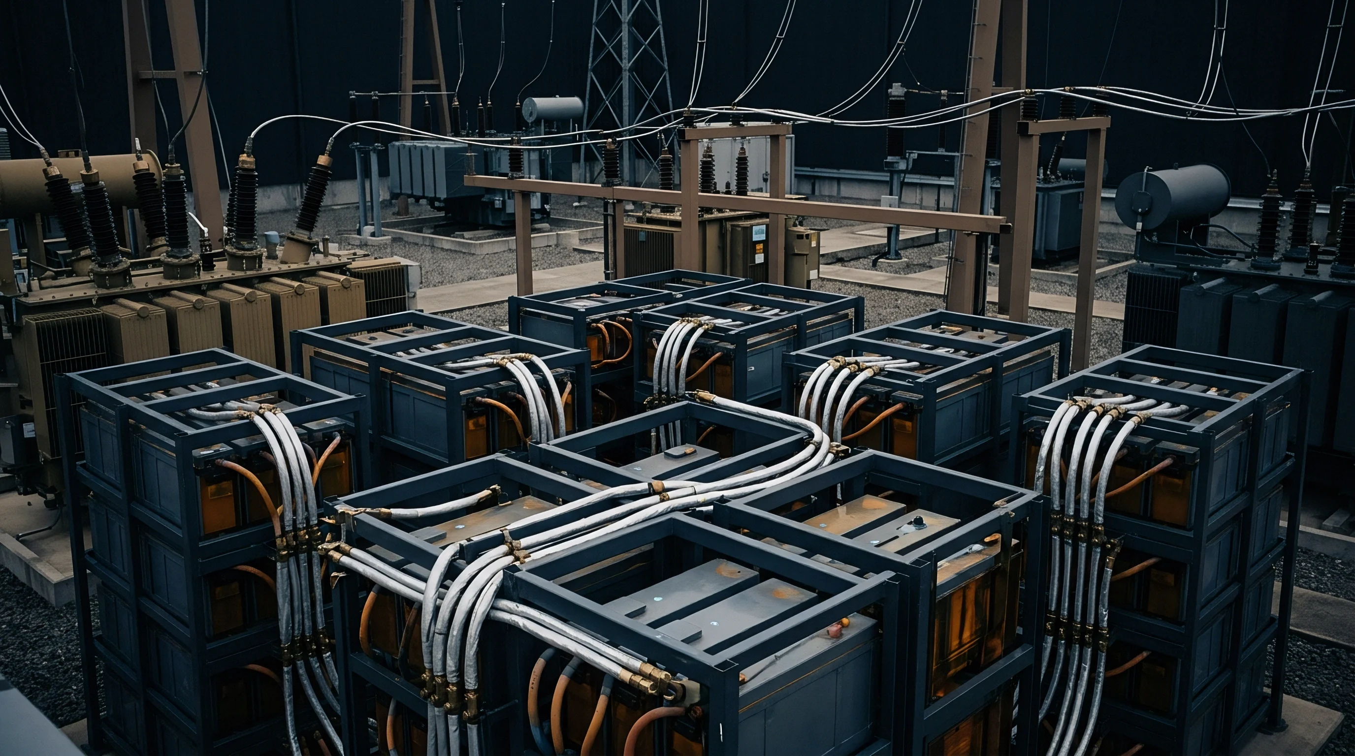
Containing cell failure before it jumps module or rack boundaries is the central problem in battery enclosure safety design. Radiant, convective, and conductive loads across sub-assembly walls dictate whether an event remains isolated to a single block or propagates through the entire energy storage container.

Why Do Module Barriers Fail under Compression?
Sustained compression collapses the internal pore volume of aerogel and fibrous insulation, raising bulk density and shifting the dominant heat transfer mechanism from gas-phase Knudsen diffusion to solid skeletal conduction. When thermal runaway occurs in a tightly compressed stack, thermal flux cuts through the thinned barrier in under half the time observed in uncompressed bench trials.
Cell swelling produces uneven pressure distribution across the pack. Compressive stress concentrates at the midpoint of large prismatic faces, pinching the barrier thinnest at the center while leaving peripheral margins relatively loose. During a runaway event, intensified conduction across this over-compressed central zone dumps heat directly into the neighboring cell core, bypassing the protective margin engineered into the original design.
- Mount surface heat flux sensors on the faces of target cells positioned directly beside the trigger cell in the module assembly.
- Drive thermal runaway by energizing a 140-watt flexible film heater against the initiation cell at a heating rate exceeding 10 degrees Celsius per minute.
- Log peak temperatures, conductive heat flux, and effluent ignition events continuously over the thirty-minute observation window.
- Disassemble the pack to inspect neighboring cell casings and internal separators for physical deformation or thermal degradation.
Rack to Rack Heat Flux Transmission Dynamics
Outdoor grid enclosures place battery racks inches apart to maximize capacity per square meter of foundation slab. If an entire rack catches fire, radiant flux leaving the open frame reaches between 45 kilowatts per square meter and 110 kilowatts per square meter at a distance of one meter.
| Exposure Location | Peak Measured Heat Flux (kW/m²) | Critical Exposure Duration (s) | Target Surface Temperature Limit (°C) | Design Mitigation Standard |
|---|---|---|---|---|
| Adjacent Cell (Same Module) | 120 – 180 | 15 – 30 | < 120 (Cell Wall) | Inter-Cell Aerogel / Mica Barrier |
| Adjacent Module (Same Rack) | 35 – 65 | 60 – 180 | < 80 (Module Casing) | Steel Heat Shield / Phase-Change Tray |
| Adjacent Rack (Side-by-Side) | 15 – 35 | 300 – 600 | < 70 (Outer Enclosure) | 12.7mm Gypsum / Mineral Wool Wall |
| External Wall (Neighboring Unit) | 5 – 12 | > 1800 | < 60 (External Surface) | 3-Meter Clear Separation Space |
Neighboring racks take on this radiant burden without obstruction, heating internal modules toward their critical decomposition points. Interposing fire-rated structural barriers interrupts this direct radiative path, keeping thermal flux on adjacent equipment under 5 kilowatts per square meter while the compromised unit burns out.
Compliance with UL 9540A Clause 8.4 determines whether outdoor grid enclosures require three-meter separation distances or permit side-by-side positioning.
Container thermal management must account for internal circulation patterns driven by HVAC blowers and gas venting velocity. Unchecked convective recirculation pushes ambient temperatures inside the container above 200 degrees Celsius within minutes, taking down low-voltage control electronics and safety interlocks on otherwise intact racks.
Skimping on internal clearance and barriers risks multi-rack propagation, complete loss of the container, and immediate revocation of local operating permits.

Exhaust
Thermal runaway off-gas consists of a volatile blend of hydrogen, carbon monoxide, methane, ethylene, and vaporized alkyl carbonates. Handling this mixture requires dedicated exhaust paths and deflagration relief that prevent internal pressure accumulation while keeping vent flames away from neighboring infrastructure.

Combustible Gas Generation and Deflagration Heat Flux
Gas release rates during rapid decomposition can overwhelm standard compartment ventilation. A single 306Ah LFP cell venting into a sealed 0.5-cubic-meter module cavity discharges upwards of 400 liters of gas in forty seconds, pushing the local atmosphere well past its lower flammability limit within moments.
Delayed ignition allows the mixture to reach stoichiometric proportions, producing deflagration overpressures that can exceed 200 kilopascals. Standard enclosure panels, doors, and latching pins fail under loads of this magnitude, launching shrapnel outward and discharging large fireballs into the yard.
- Gas accumulation volume calculation pairs peak mass discharge rates with worst-case multi-cell cascading scenarios to size container exhaust capacity.
- Duct pressure drop limits restrict internal flow resistance so deflagration relief panels can vent without over-pressurizing the main enclosure shell.
- Flame arrester sizing criteria block external ignition fronts from flashing back into unvented battery cabinets.
- Purge airflow distribution patterns wash out stagnant corners where hydrogen and carbon monoxide might otherwise pool past their lower flammability thresholds.

NFPA Venting Specifications and Deflagration Suppression
Relief vents sized per NFPA 68 match relief area to peak gas generation rates and fundamental burning velocity. Panels calibrated to burst between 10 to 20 kilopascals release early in the pressure rise, channeling expanding combustion gases away from service aisles and neighboring enclosures.
Gas deflagration vents direct flame discharge outward rather than containing thermal load inside adjacent battery racks.
Radiant and convective flux at the exit plane of an open vent panel can reach 150 kilowatts per square meter. Exhaust ducting and clearance envelopes must route this exhaust column upward or into open buffer corridors to shield transformers, switchgear, and perimeter fencing from direct flame contact.
Under NFPA 855 Clause 4.3.2, unvented systems larger than fifty kilowatt-hours require a minimum ten-foot buffer from lot lines and exposed buildings, directly driving up balance-of-plant acreage requirements and civil costs.


Stipulation
Procuring and deploying utility-scale storage takes place inside strict regulatory boundaries. Grid interconnection agreements, local permitting authorities, and insurers demand verifiable test data showing that runaway heat flux stays within defined safety envelopes across all realistic failure scenarios.

UL 9540 System Listing Boundaries and Site Footprints
UL 9540 listing hinges on empirical heat flux and flame propagation measurements obtained through UL 9540A testing. Final system certificates define strict construction parameters: maximum module capacity, approved inter-cell insulation types and thicknesses, structural setback distances, and explosion venting ratings.
Swapping out specified inter-cell insulation materials or altering internal module spacing without recertification invalidates the UL 9540 listing. Operating modified hardware breaches power purchase agreement covenants, trips policy exclusions in project insurance underwriting, and invites stop-work or shutdown orders from local fire marshals.

EPC Warranty Conditions and Liability Allocation
Engineering, Procurement, and Construction agreements govern how thermal failure risks are divided among cell vendors, system integrators, and project owners. Technical audits during procurement need to verify that cell-level supplier guarantees match the boundary conditions documented in module certification files.
Standard warranty provisions void coverage if telemetry shows cells operated outside temperature, current, or SOC windows before a runaway occurred. Buyers protect themselves by tying warranty terms directly to audited UL 9540A unit-level test reports, holding vendors to performance demonstrated during independent laboratory trials.
Clear contractual risk allocation requires closing gaps between cell test certificates, container fire ratings, and the site-specific emergency response plan approved by local authorities.