Coupled Thermomechanical Degradation under Variable Mechanical Preload Pressures in Commercial Prismatic Battery Packs
Controlled mechanical preload pressures between 0.10 and 0.35 MPa prevent electrode delamination while avoiding separator pore creep and particle microcracking.


Preload
Commercial prismatic cells face dynamic internal forces during routine cycling. Tier 1 manufacturer specifications set initial mounting stress between 0.05 MPa and 0.30 MPa at beginning-of-life in a discharged state. Clamping the large flat faces of a prismatic can keeps the internal jelly rolls or stacked electrode sheets, separator membranes, and aluminum casing walls in continuous contact.
This mechanical coupling stabilizes ionic pathways and prevents planar delamination during high-current discharge.
Deviating from the target clamping window produces distinct degradation patterns. Too little tension allows internal electrode layers to separate locally during microscopic contraction cycles. The resulting gap lengthens the ionic transport path, appearing on impedance spectroscopy as an enlarged mid-frequency charge-transfer semicircle.
Excessive clamping force crushes separator micropores, raising high-frequency ohmic resistance and triggering localized lithium plating near electrode margins where current density concentrates.
A minimum uniform clamping stress of 0.15 MPa at 10 percent state of charge limits interfacial charge-transfer resistance growth to under 8 percent across the initial 1,000 full-depth cycles.
Different cathode chemistries respond quite differently to face loads. Lithium iron phosphate exhibits minimal bulk crystal deformation during cycling, but the graphite anodes paired inside these cells expand by up to 10 percent at full lithiation. High-nickel layered oxides like NMC811 undergo anisotropic lattice contraction and expansion during phase transitions, generating severe localized microstresses within secondary particle agglomerates.
Pack design requires balancing these chemical behaviors against structural chassis stiffness.

Mechanical Pressure Windows across Lithium Chemistries
Comparing commercial cell families shows how heavily optimum assembly loads depend on active material composition and cell geometry. The table below outlines empirical boundaries established during long-term cycling evaluations.
| Chemistry And Nominal Capacity | Optimal Initial Load Range | Under-Clamping Consequence | Over-Clamping Consequence | Beginning-Of-Life Retained Yield |
|---|---|---|---|---|
| LiFePO4 280Ah (LFP/Graphite) | 0.10 to 0.25 MPa | Electrode buckling, delamination | Separator pore closure, lithium plating | 99.4% |
| NMC622 150Ah (NMC/Graphite) | 0.15 to 0.30 MPa | Contact loss, accelerated dry-out | Cathode particle fracture, rapid fade | 98.9% |
| NMC811 100Ah (NMC/Graphite-SiOx 5%) | 0.20 to 0.40 MPa | Particle isolation, heavy SEI growth | Severe microcracking, transition metal loss | 98.2% |
| LTO 50Ah (NMC/LTO) | 0.05 to 0.15 MPa | Minimal capacity penalty | Unnecessary structural pack mass penalty | 99.7% |
Adding silicon to graphite anodes alters stack mechanics significantly. A 5 weight percent silicon oxide blend doubles reversible electrode thickness variation, multiplying mechanical work on the module enclosure during each half-cycle. Module designers accommodate this by placing compliant cellular materials between neighboring cells to damp pressure spikes before internal loads reach structural yield thresholds.
Interfacial Resistance under Variable Compression
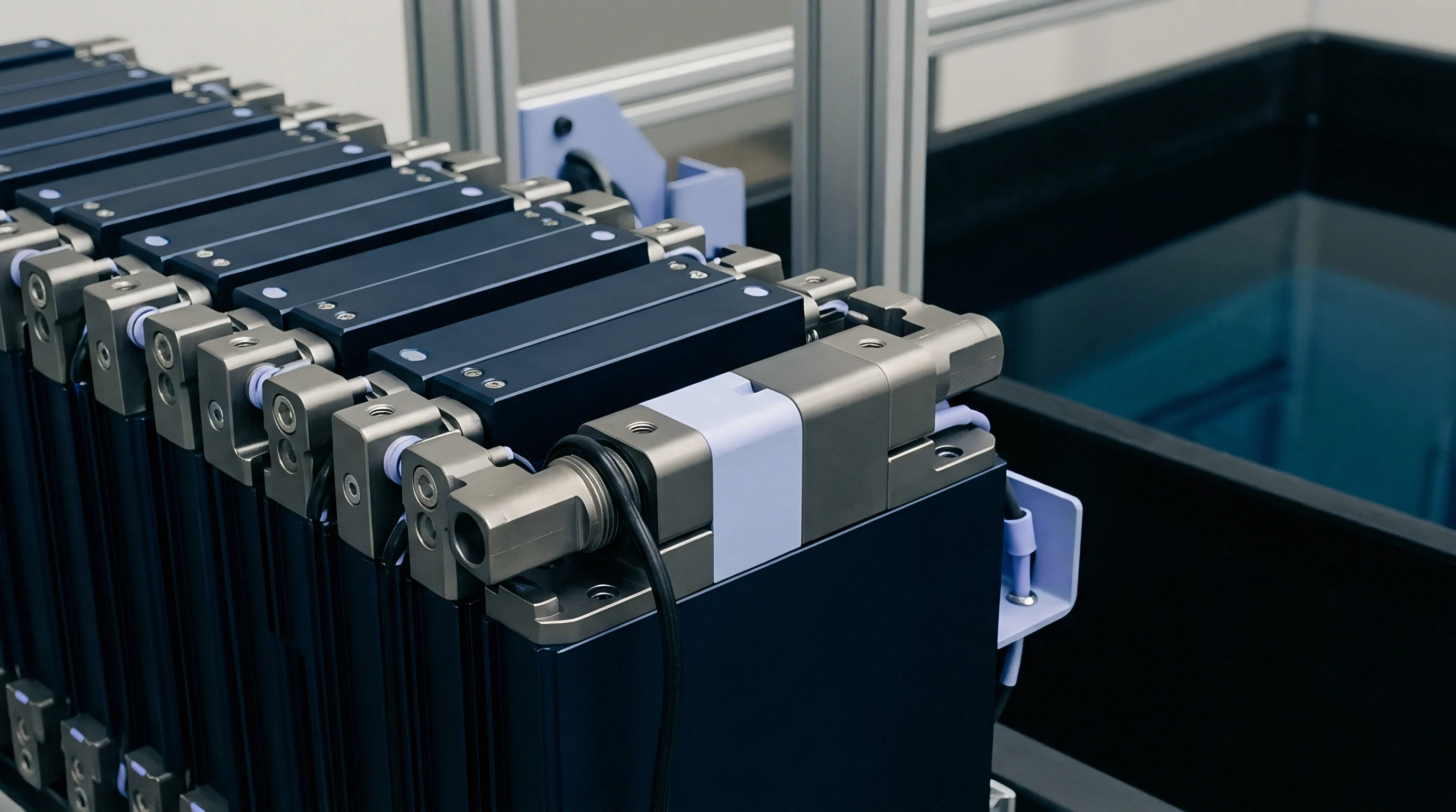
Electrical and thermal interfaces inside the module respond directly to external constraint. Increasing face load compresses microscopic surface asperities between the aluminum cell casing and external liquid-cooled cold plates. This smoother contact improves boundary conductance, reducing the temperature drop across the thermal interface material.
Moderate external loads also compact the electrode coating, improving electron percolation networks across conductive additive matrices.
Premature capacity fade often stems from pack retention bands permitting excessive breathing room during field deployment.


Breathing
Volumetric changes during lithiation cause cyclic mechanical displacement, known in pack engineering as cell breathing. In graphite-based prismatic cells, lithium intercalation into graphene layer galleries drives c-axis expansion, expanding graphite crystallites by roughly 10 percent. Multiplied across 40 to 80 internal jelly roll layers within a standard commercial prismatic can, unconstrained cell expansion can reach 1.5 to 3.5 millimeters on the bench.
Pack structures constrain this expansion using rigid end plates and steel tie rods. Restraining the outer boundary converts geometric breathing into heavy cyclic normal stress. In a 280Ah prismatic cell held at constant volume, internal mechanical stress rises from a baseline of 0.15 MPa at zero percent state of charge to over 0.85 MPa at 100 percent state of charge.
This stress cycles continuously, subjecting internal polymer separators and active material binders to thermomechanical fatigue.
- Initial Phase Dilation produces modest lateral strain during staging from dilute stage 4 to stage 3 graphite compounds below 25 percent state of charge.
- Main Two-Phase Plateau delivers steep stress elevation between 30 and 70 percent state of charge as phase transformation proceeds toward fully lithiated stages.
- Full Lithiation Peak concentrates maximum compressive loads against separator coatings, peaking near top of charge.
- Delithiation Contraction releases mechanical face pressure rapidly during initial discharge, creating transient local stress relaxations across the active layers.
Separator health deteriorates under constant cyclic compression. Standard 12-micrometer wet-process polyethylene membranes coated with alumina nanopowder withstand moderate compressive loads without structural failure. However, when peak loads exceed 1.2 MPa under high-temperature cycling, polymer fibrils undergo creep deformation.
This thinning closes sub-micron pore networks, restricting lithium ion flux and elevating internal resistance.
Separator pore throttling under sustained mechanical over-compression shifts the active voltage plateau downward by forty millivolts during standard two-hour discharge rates.
Electrolyte distribution inside the prismatic casing shifts continuously through breathing cycles. Peak compression during charge squeezes liquid electrolyte from the core of the jelly roll into peripheral voids near the can margins. On discharge, electrode contraction creates capillary suction that pulls liquid back into microscopic pores.
High charge rates combined with rigid constraints disrupt this capillary refilling, causing persistent local dry-out in high-current regions.

Anode Dilation versus Cathode Contraction Mechanics
Electrochemical balance between opposing electrodes dictates net can wall displacement. Layered oxide cathodes like NMC contract by roughly 1.5 to 3.0 percent along active crystallographic planes during delithiation as lithium ions leave octahedral sites. This cathode lattice shrinkage partially offsets graphite anode expansion during charge.
Lithium iron phosphate, however, retains an invariant olivine crystal volume during charge, so net expansion in LFP cells directly reflects anode swelling without cathode offset.

Why Does Solid Electrolyte Interphase Thickening Escalate Stress?
Parasitic reactions at the graphite-electrolyte interface continuously consume cyclable lithium to form inorganic and organic decomposition products. This solid electrolyte interphase layer builds up over thousands of operating hours, filling pore volume and permanently thickening electrode coatings. This irreversible expansion compounds with daily electrochemical breathing.
After five years, a cell held under constant-volume restraint can exhibit a baseline stress at zero percent state of charge that exceeds its original beginning-of-life peak stress at full charge.
Unmanaged irreversible expansion eventually deforms rigid structural end plates regardless of initial torque specifications.


Fracture
Secondary particle agglomerates in high-energy cathode coatings suffer high internal stresses during rapid charging. Concentration gradients between particle shell and core create mismatch strains that exceed the tensile strength of primary crystallite grain boundaries. Repeated cycling under high external preload pressure accelerates this damage, driving microcracks through polycrystalline NMC spheres.
Microcracking isolates primary grains from the conductive carbon network. Electrically isolated cathode fragments can no longer contribute to redox capacity, leading to permanent capacity loss. Freshly exposed crack surfaces also react with organic carbonate solvents, leaching transition metals like manganese, cobalt, and nickel from the lattice.
These dissolved cations cross the separator and deposit on the graphite anode, poisoning the protective surface film and accelerating lithium consumption.
Standard ISO 12405-4 cycling regimes reveal that cathode particle isolation accounts for more than half of all non-recoverable capacity loss in high-nickel prismatic packs operated above 0.50 MPa.
Lithium plating is an acute operational risk tied to local overpotentials and mechanical pressure fields. When separator pores are partially pinched under heavy clamping, mass transfer resistance through the liquid electrolyte rises sharply. If the anode potential drops below 0.0 V versus Li/Li+ during high-rate charging, metallic lithium deposits directly on the graphite surface.
These metallic deposits react vigorously with electrolyte solvents, releasing heat and forming dead lithium that no longer participates in cycling.

Particle Cracking and Lithium Plating Interactions
Mechanisms of mechanical degradation and electrochemical side reactions reinforce one another over operational lifespans. The table below details interaction modes, their primary physical indicators, and observable consequences in operational battery packs.
| Failure Mechanism | Driving Stress Factor | Electrochemical Signature | Physical Inspection Finding | Severity Index |
|---|---|---|---|---|
| Cathode Microcracking | Intergranular stress, high C-rate | Impedance semicircle doubling | Particle pulverization, core fragmentation | High |
| Separator Pore Creep | Sustained external preload >0.6 MPa | Ohmic DC resistance elevation | Membrane thinning, localized translucency | Medium |
| Lithium Metal Plating | Electrode over-compression, cold charging | High-voltage plateau during rest | Silver-gray mossy deposits on anode | Critical |
| Anode Edge Delamination | Localized shear strain, under-clamping | Low coulombic efficiency, capacity drop | Active coating separation from copper foil | High |
Pressure distribution across a prismatic can face is rarely uniform. Typical cells bulge most at the geometric center of the wide side wall, while edges and corners remain constrained by rigid aluminum casing welds. This creates steep internal pressure gradients: central electrode regions suffer severe over-compression, while peripheral zones see low contact force and localized delamination.

Thermal Contact Resistance and Heat Rejection Penalties
Uneven mechanical pressure distorts heat rejection pathways through the pack enclosure. Under low clamping pressure, interfacial air pockets between the cell base and thermal sink create contact resistances exceeding 3.5 K-cm²/W. Heat generated during fast charging accumulates in the cell core, pushing internal temperatures above 45°C while external sensors read normal levels. These elevated core temperatures accelerate active material dissolution and breakdown of the solid electrolyte interphase, raising the risk of localized thermal runaway.
Underestimating particle fracture mechanics leads directly to pack-level thermal runaway events and costly structural warranty campaigns.

Shim
Passive mechanical compensation systems mitigate cyclic stress swings across extended operational periods. Commercial battery modules incorporate elastomeric compression pads, microcellular polyurethanes, or aerogel insulation blankets between adjacent prismatic cells. These compliant layers absorb reversible cell breathing during daily charge cycles while resisting permanent mechanical set under long-term irreversible expansion.
Microcellular polyurethane foams demonstrate non-linear stress-strain curves with an extended flat plateau region. Within this plateau, foam pads absorb significant physical displacement while maintaining transmitted normal stress within the desired 0.10 to 0.35 MPa window. Module engineers determine pad thickness and initial installation compression based on cell swelling models across target service lifespans.
Stiff solid silicone pads generate steep force spikes under minimal displacement, whereas excessively soft open-cell foams bottom out early, losing compliance before end-of-life swell limits arrive.
- Microcellular Polyurethane provides wide operational displacement plateaus with low compression set across standard thermal ranges from minus 20°C to 50°C.
- Aerogel Composite Sheets combine high mechanical compliance with exceptional thermal barrier properties, preventing cell-to-cell thermal propagation during safety events.
- Silicone Elastomers maintain mechanical elasticity over wide thermal extremes from minus 40°C to 80°C, albeit with steeper progressive stiffness curves.
- Metallic Wave Springs deliver precise, highly linear mechanical resistance across millions of displacement cycles without material aging risks.
End plate design dictates structural boundary stiffness at the module perimeter. Cast aluminum or stamped high-strength steel end plates must resist cyclic bending moments generated by accumulated cell forces. In a module containing 12 series-connected 280Ah prismatic cells, collective swelling force can exceed 15 kilonewtons at end of life.
End plates engineered with inadequate section modulus bow outward at the center, releasing compression on central cells while concentrating destructive edge loads on exterior cells.

Foam Compression Curves and Spring Plate Retention
Stress-strain response curves for compliant materials dictate the mechanical operating point of the assembled module. The selection process evaluates force response at both zero percent state of charge at beginning of life and 100 percent state of charge at end of life.
| Pad Material Class | Nominal Uncompressed Thickness | Initial Compression Set | Compression Force Deflection At 25% | Thermal Conductivity |
|---|---|---|---|---|
| Microcellular Polyurethane (Medium Density) | 2.0 mm | < 5.0% (at 70°C) | 0.12 MPa | 0.08 W/m·K |
| High-Density Polyurethane | 1.5 mm | < 3.0% (at 70°C) | 0.28 MPa | 0.11 W/m·K |
| Silicone Foam (Closed Cell) | 2.5 mm | < 2.5% (at 100°C) | 0.18 MPa | 0.07 W/m·K |
| Silica Aerogel Blanket with PET Facing | 2.0 mm | < 8.0% (at 80°C) | 0.15 MPa | 0.02 W/m·K |
Long-term material creep shifts initial calibration parameters over multi-year field deployments. Polyurethane materials experience stress relaxation under sustained static loads, lowering the baseline holding force during prolonged vehicle parking periods. Pack specifications account for this relaxation by over-torquing tension bands during factory integration, ensuring residual retention pressure remains above minimum contact limits after five years of service.

End Plate Deflection and Cell Swell Management
Structural validation of module enclosures includes FEA simulation of end plate deflections under end-of-life expansion loads. Tension straps manufactured from 304 stainless steel or high-tensile woven composite fibers secure end plates against lateral displacement. Laser-welded side bands provide minimal elongation under load, preserving cell face parallelism and preventing localized shear deformations across internal separator sheets.
Standard delivery agreements specify that total module face deflection across the complete pack operational lifespan shall not exceed 0.8 millimeters per cell stack under UN 38.3 vibration and thermal shock compliance clauses.


Exposure
Warranty exposure in grid-scale energy storage and commercial transport fleets correlates directly with mechanical pack integrity. When mechanical preload systems fail to accommodate cell breathing, capacity fade accelerates non-linearly, pushing fleets beyond contractual 80 percent retention thresholds years before amortization models close. Replacement costs for defective multi-megawatt-hour installations rapidly exceed original equipment margins.
Landed cost calculations incorporate the mass, volume, and tooling overhead of mechanical retention hardware. High-strength structural end plates, precision tension straps, and high-performance compliant foam sheets add between 4 and 8 percent to total module bill of materials costs. Removing compliant pads to minimize upfront cell integration expenditure invariably triggers early field failures, transferring financial liability from engineering budgets to warranty reserve accounts.
A pack design operating with uncompensated mechanical expansion accumulates warranty liabilities exceeding eighteen percent of total contract value within thirty-six months of commissioning.
Incoming cell inspections verify dimensional tolerances and can wall flatnesses before integration into rigid fixtures. High-capacity prismatic cells with can wall convexities exceeding 0.3 millimeters distort pack pressure distributions from the first assembly stage. Automated optical gauging and laser thickness profiling on incoming dock shipments reject non-conforming cells before integration into modules, eliminating localized over-compression points before cells encounter external clamping loads.

Landed Cost and Warranty Accrual Sensitivities
Financial modeling of large-scale battery projects links mechanical design rigor directly to project internal rate of return. A 100 MWh containerized energy storage project built with optimized compliant shims and rigid end plates maintains linear degradation curves, reaching 6,000 cycles before repowering. The identical cell lot assembled into rigid, non-compliant fixtures reaches the capacity knee-point at 3,200 cycles due to separator pore creep and particle fracture.
The cost differential in early cell replacements shifts project economics into negative net present value territory.

Qualification Protocols for Pack Fixture Durability
Comprehensive qualification regimes subject fully constrained multi-cell fixtures to accelerated aging profiles. Test stations combine continuous charge-discharge cycling at elevated C-rates with active environmental chamber temperature swings from minus 30°C to 60°C. In-situ load cells embedded behind structural end plates record real-time force evolution, tracking stress relaxation, cyclic breathing peaks, and irreversible plastic deformations throughout testing campaigns.
Whether active mechanical preload adjustment mechanisms using shape memory alloys or hydraulic tensioners can economically replace passive elastomeric shims in future heavy-duty transport applications remains an open industry challenge.