Sodium Ion Sacrificial Additive Chemistry Mechanics
Sacrificial sodium additives offset initial hard carbon capacity loss to increase sodium-ion cell energy density and reduce landed cost per kilowatt-hour.


Deficit
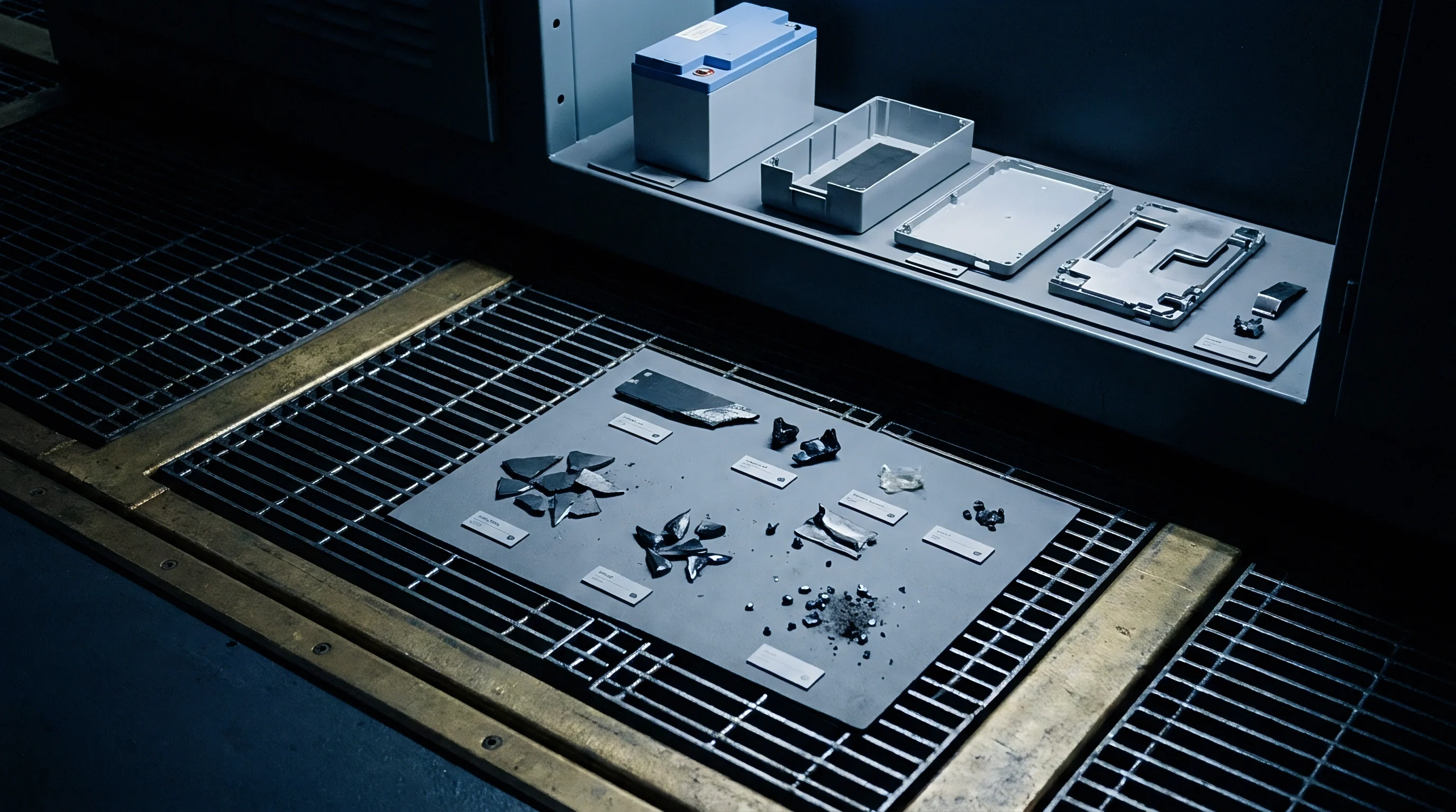
Hard Carbon Anode Trapping Dynamics
Porous carbon structures take up sodium ions through intercalation between disordered graphene sheets and irreversible pore condensation. On the initial charge, pristine electrolyte solvents break down at the carbon interface between 1.2 V and 0.2 V vs. Na/Na+.
This reduction forms a solid electrolyte interphase containing sodium carbonate, sodium alkyl carbonates, sodium hydroxide, and sodium fluoride. The process permanently traps a significant fraction of mobile sodium ions inside the boundary layer, removing them from subsequent discharge cycles.
Sodium trapped within this boundary layer cannot be recovered during subsequent discharge cycles.
The scale of this initial loss tracks directly with the hard carbon’s specific surface area and defect density. High-surface-area materials built for rapid charging often exhibit first-cycle irreversible capacity losses from 15 percent to over 30 percent. Sub-nanometer micropores trap active sodium through binding at dangling bonds and surface oxygen groups.
Left uncompensated, this consumption draws active sodium straight from the cathode lattice, lowering both reversible capacity and cell-level energy density.
Cathodes such as layered transition metal oxides, polyanionic compounds, and Prussian blue analogues are synthesized with a fixed inventory of sodium ions. O2-type and P2-type layered oxides can lose up to a third of that sodium just to build the anode interphase layer. This leaves the cathode sodium-deficient in the discharged state, holding transition metal ions in higher oxidation states and sharply reducing usable milliampere-hours per gram.
Electrolyte Reduction and Phase Boundary Losses
Trace moisture accelerates solvent reduction, forming insoluble inorganic sodium salts that thicken the interphase layer. Standard sodium salts like sodium hexafluorophosphate or sodium perchlorate in carbonate mixtures undergo secondary side reactions that continuously consume active sodium during early cycling. Structural degradation of carbon pores can further lock trapped charge.
Beyond micropore trapping, sodium binds irreversibly to phenolic, carbonyl, and carboxyl groups on carbon edge planes. These sites reduce at potentials higher than those required for intercalation, depleting active sodium before structural charge storage even begins. The net initial deficit is thus the sum of SEI layer formation, functional group binding, and trapping within closed nanopores.
Initial sodium loss in hard carbon anodes reaches 22 percent at a current density of 0.1C when specific surface area exceeds 15 square meters per gram.
Offsetting this sodium loss without adding cathode mass requires an auxiliary internal sodium source. Simply adding extra cathode material reduces gravimetric and volumetric energy density, since the depleted cathode mass sits in the cell as dead weight. Meanwhile, pre-sodiumating the anode with metallic sodium foil or reactive organometallic solutions introduces severe processing hazards and moisture sensitivity on high-speed lines.
Sacrificial cathode additives solve this imbalance by supplying extra sodium ions during the initial charge. They decompose irreversibly within the cathode’s normal operating voltage window, releasing sodium to form the anode interphase while leaving behind inert residues or volatile gases. Integrating them effectively depends on matching their oxidation potentials, decomposition pathways, and residual phase behavior to the primary cathode.
Continuous sodium release from dense sacrificial particles faces fundamental kinetic barriers to avoid triggering localized surface oxidation on adjacent active materials.


Salt

Sacrificial Compounds and Oxidation Kinetics
Sacrificial sodium additives fall into several chemical families: oxides, oxocarbons, nitrides, sulfides, and sodium-rich transition metal complexes. Each operates through distinct oxidation mechanisms defined by its decomposition potential, gravimetric sodium yield, and reaction byproducts. Choosing the right additive requires aligning its oxidation potential with the upper cutoff voltage of the primary cathode.
Sodium oxide offers a theoretical capacity of 865 mAh/g, oxidizing into sodium ions and oxygen gas. Breakdown occurs above 3.5 V vs. Na/Na+ through a multi-step pathway.
Because pristine Na2O is electronically insulating and kinetically slow, it requires close contact with conductive carbon coatings or catalytic transition metal particles to decompose fully during formation charging.
Sodium oxalate provides a theoretical capacity of 400 mAh/g, releasing sodium ions and carbon dioxide gas between 3.8 V and 4.2 V vs. Na/Na+. Complete breakdown yields two moles of electrons and two moles of CO2 per mole of oxalate salt, reacting cleanly without leaving solid residue.
Organo-sodium salts like disodium rhodizonate and sodium squarate decompose at lower potentials, operating between 3.2 V and 3.6 V vs. Na/Na+. These oxocarbons release sodium while converting into stable carbonaceous residues or volatile organic fragments.
Their lower activation threshold prevents cathode overcharge, avoiding structural degradation or transition metal dissolution on the first charge.

Nitride, Sulfide, and Inorganic Donor Pathways
Sodium nitride yields 968 mAh/g via low-voltage oxidation, evolving nitrogen gas above 3.0 V vs. Na/Na+. This makes it suitable for lower-voltage cathodes like Prussian blue derivatives.
However, its extreme moisture sensitivity complicates manufacturing, as exposure to ambient humidity immediately produces caustic sodium hydroxide and ammonia gas.
Sodium sulfide delivers 687 mAh/g, oxidizing to sodium ions and elemental sulfur or polysulfides around 3.2 V vs. Na/Na+. Despite its high sodium content, dissolved polysulfides shuttle across carbonate electrolytes to the anode, causing severe self-discharge.
Sulfide additives therefore require encapsulation or surface coatings to keep sulfur out of the electrolyte.
Sodium-rich transition metal compounds like Na2CrO2, Na5FeO4, and Na3FeF6 decompose through structural transformation rather than gas release. For example, Na2CrO2 yields one mole of sodium per formula unit near 3.8 V vs. Na/Na+, leaving an inactive or partially active NaCrO2 phase in the cathode.
These non-gaseous donors eliminate cell swelling, though their solid residues add dead weight to the electrode.
Selecting an additive involves balancing theoretical capacity against chemical stability, oxidation voltage, and byproduct behavior. Gaseous donors like sodium oxide yield high sodium per gram and minimize dead mass, but demand strict handling. Solid-residue additives, by contrast, are generally easier to process in standard dry-room environments due to lower moisture sensitivity.

Additive Selection Criteria
Evaluating sacrificial candidates requires matching their properties against manufacturing constraints and cell operating windows.
- Oxidation potential alignment ensures the donor releases its sodium before the primary cathode reaches its upper voltage limit.
- Gravimetric sodium yield dictates how much additive is needed to offset initial anode losses without excessively diluting energy density.
- Moisture stability index sets the dry-room humidity limits required during slurry preparation and coating.
- Decomposition byproduct state determines whether processing requires high-vacuum degassing or special residual phase management.
- Electronic conductivity profile dictates the conductive carbon addition needed to ensure complete particle reaction.
Parasitic side reactions during early formation steadily drain the mobile sodium inventory.
Performance metrics for common sacrificial sodium additives tested under standard baseline conditions are detailed below.
| Additive Formula | Theoretical Capacity (mAh/g) | Decomposition Potential (V vs Na/Na+) | Primary Byproduct | Moisture Sensitivity |
|---|---|---|---|---|
| Na2O | 865 | 3.5 – 3.9 | O2 gas | Extreme (forms NaOH) |
| Na2C2O4 | 400 | 3.8 – 4.2 | CO2 gas | Moderate |
| Na3N | 968 | 3.0 – 3.4 | N2 gas | Extreme (forms NH3) |
| Na2S | 687 | 3.1 – 3.5 | S / Polysulfides | High (forms H2S) |
| Na2CrO2 | 235 | 3.7 – 4.0 | Solid NaCrO2 | Low |
| Na2C4O6 | 250 | 3.2 – 3.6 | Solid residue / CO2 | Low to Moderate |
Particle size strongly influences oxidation kinetics. Coarse additive particles above five micrometers suffer from high internal impedance, leading to incomplete oxidation during formation charging. Downsizing to the nanoscale or coating particles with amorphous carbon reduces charge-transfer resistance, allowing full sodium extraction at lower overpotentials.
Poor particle sizing or mismatched oxidation potentials leave unreacted additive in the cathode past initial formation. These pockets act as localized stress points and insulating sites. During extended cycling, voltage spikes can trigger late oxidation of residual additive, causing gas evolution inside sealed cells, pouch expansion, delamination, and severe capacity loss.


Gassing

Decomposition Reactions and Gas Evolution
Gas-evolving additives alter internal pressure during cell formation. Releasing oxygen, carbon dioxide, or nitrogen requires controlled venting to prevent mechanical damage to the electrode stack. Evolution rates depend on formation temperature, current density, and particle surface area.
Oxidizing sodium oxide releases molecular oxygen via multi-step electron transfer. Free oxygen in carbonate electrolytes reacts aggressively with solvents like ethylene carbonate and dimethyl carbonate, producing carbon monoxide, carbon dioxide, and polymeric species that raise electrolyte viscosity and charge-transfer resistance.
Sodium oxalate decomposes more cleanly, yielding carbon dioxide. Because CO2 dissolves more readily in carbonate electrolytes than oxygen or nitrogen, immediate pressure buildup in pouch cells is lower during early formation. Dissolved CO2 also aids SEI formation on hard carbon anodes, forming a dense, conductive sodium carbonate layer that inhibits further electrolyte breakdown.
Evolved gaseous byproducts must be completely evacuated during the initial formation process.

Slurry Chemistry and Manufacturing Interferences
Adding highly reactive additives to wet slurry formulations presents chemical stability hurdles. Basic species like sodium oxide and sodium nitride react with trace moisture in N-methyl-2-pyrrolidone or aqueous media. The resulting hydroxide ions drive slurry pH above 12, triggering dehydrofluorination and gelation of polyvinylidene fluoride (PVDF) binders.
Gelation ruins slurry homogeneity, causing agglomeration and uneven coating weights on aluminum current collectors. Cross-linked binders lose elasticity, leading to foil cracking during calendering. Preventing this requires passivating particle surfaces with organosilane coatings, carbon shells, or protective polymers to isolate the active core from moisture and solvent until formation.
Maintaining dry-room dew points well below ambient levels protects moisture-sensitive formulations from degradation.
Basic surface sites on unreacted particles also react with ambient moisture and CO2 during storage, forming resistive crusts of sodium hydroxide and sodium carbonate. These crusts raise charge-transfer impedance and push decomposition potentials beyond the electrolyte’s stability window, resulting in incomplete sodium extraction.
Outgassing and slurry instability introduce distinct failure mechanisms across production and cycling:
- Binder dehydrofluorination causes rapid viscosity spikes and brittle coatings.
- Excess oxygen evolution oxidizes electrolyte solvents, building internal pressure and cell impedance.
- Incomplete formation degassing leaves gas pockets between separator and electrode, creating current density hotspots.
- Polysulfide dissolution from sulfide additives causes active material shuttling that degrades the hard carbon interphase.
- Secondary outgassing during cycling occurs when residual additive decomposes late in cell life under high voltage or elevated temperature.
Is Residual Active Sodium Manageable during Cell Degassing?
Managing evolved gases during pouch or rigid-can formation requires multi-stage vacuum degassing. Pouch cells use temporary gas-bag extensions to collect gas produced during the initial charge up to 4.2 V vs. Na/Na+.
After formation, the bag is pierced under vacuum to draw out byproducts before final thermal sealing.
Although sacrificial additives are rated to remain inert in slurries up to 0.5 percent relative humidity, factory audits show binder cross-linking and gelation occurring at moisture levels as low as 0.1 percent. Preparing solvents and mixing slurries under argon or at dew points below minus 50 degrees Celsius prevents premature hydrolysis and binder breakdown.


Curve

Voltage Profiles and Half-Cell Balancing
Sacrificial additives alter full-cell voltage profiles during initial charge-discharge cycles. On the first charge sweep, the profile shows an extended low-voltage plateau or oxidation shoulder corresponding to additive decomposition. This shoulder appears before significant oxidation of the primary cathode, confirming the donor is actively releasing sodium ions.
In a full cell pairing a sodium layered oxide cathode with a hard carbon anode, adding 5 weight percent disodium squarate lowers the charge energy needed to reach 3.0 V. The additive supplies the sodium consumed by SEI growth on the hard carbon, keeping the cathode from becoming sodium-deficient. Consequently, the cell exhibits a higher operating discharge plateau and superior capacity retention compared to uncompensated cells.
Systematic shifts in overpotential alter the practical voltage range required for full decomposition.
Electrode balancing must account for milliampere-hours supplied by both the primary cathode and the sacrificial donor. Total initial sodium capacity from the positive electrode must match the first-cycle charge capacity of the hard carbon anode, including its irreversible loss. Precise balancing avoids sodium plating on the anode at full charge, which happens if active sodium exceeds the hard carbon’s reversible intercalation capacity.
Inadequate sodium compensation directly penalizes usable discharge capacity across subsequent cycles.
Full-cell performance comparisons for sodium-ion formulations with zero, three, and five weight percent additive additions appear in the table below.
| Additive Content (wt%) | First Cycle Efficiency (%) | Specific Capacity (mAh/g cathode) | Initial Cell Energy Density (Wh/kg) | Capacity Retention at 1000 Cycles (%) |
|---|---|---|---|---|
| 0% (Control) | 74.2 | 112.5 | 128.0 | 71.5 |
| 3% Na2C2O4 | 86.8 | 131.0 | 149.2 | 82.1 |
| 5% Na2C2O4 | 94.5 | 142.8 | 162.5 | 88.4 |
| 5% Na2O (Coated) | 98.1 | 148.2 | 168.7 | 85.2 |
| 7% Na2O (Overcharged) | 97.8 (Plating Observed) | 146.0 | 161.0 | 62.0 |
Rate Capability and Long-Term Cycling Degradation
How additives affect long-term impedance depends on whether their byproducts are gaseous or solid. Clean gas evolution leaves no solid residue, preserving cathode porosity and ionic diffusion channels. Solid residues, however, increase interparticle contact resistance, slightly degrading high-rate capability.
Uncontrolled impedance growth at the cathode boundary restricts rate performance under heavy current loads.
Differential capacity curves (dQ/dV vs. voltage) provide a sensitive check for complete additive oxidation. A clear dQ/dV peak during the initial charge confirms decomposition within the expected voltage window. The absence of this peak on subsequent cycles confirms the reaction is fully irreversible and will not act as a parasitic charge sink during operation.
Differential capacity monitoring confirms complete sacrificial additive extraction when oxidation peaks disappear entirely during second-cycle charge sweeps.
Cells with optimized additive loadings maintain higher coulombic efficiency over extended cycling. Satisfying the hard carbon SEI demand during formation suppresses late-stage sodium consumption, slowing capacity fade and extending operational life under fast charging and broad temperature ranges.
Excessive sodium loading risks metallic sodium deposition, particularly when charging at low ambient temperatures.


Screening

Residual Phase Quantification and Analytical Verification
Quality control for additive integration relies on precise analytical techniques to detect unreacted phases and measure active sodium inventory. X-ray diffraction (XRD) of fully formed cathodes quantifies crystalline phases; unreacted additive shows up as distinct Bragg peaks, signaling incomplete decomposition during formation.
Unreacted crystalline residues block lithium and sodium diffusion pathways across the active material matrix.
Trapped gas bubbles distort internal cell pressure profiles and physically displace active contact areas.
Gas chromatography-mass spectrometry (GC-MS) analyzes gas sampled from pouch bags during formation. Measuring oxygen, carbon dioxide, and nitrogen confirms whether additive oxidation followed the intended stoichiometry. Traces of carbon monoxide or volatile fluorides indicate solvent breakdown or electrolyte degradation caused by localized overcharging around coarse particles.
Inductively coupled plasma optical emission spectroscopy (ICP-OES) determines sodium-to-transition-metal ratios in pristine and formed electrodes. Comparing these ratios before and after formation verifies the exact amount of sodium extracted from the donor and transferred to the hard carbon interphase.
Formation Procedures and Verification Protocols
Verifying sodium replenishment and additive decomposition requires a structured formation protocol:
- Mount assembled cells onto temperature-controlled formation channels maintained at 25 degrees Celsius with continuous voltage logging.
- Apply a low-current C/20 charge up to the target additive oxidation shoulder to initiate controlled donor decomposition.
- Monitor differential pressure sensors on cell gas ports to track gas evolution rates and confirm reaction onset.
- Hold potential at the decomposition plateau until current decays below C/100, ensuring complete sodium extraction.
- Ramp current density to C/10 to charge the cathode to its full upper cutoff voltage while logging total capacity.
- Perform deep vacuum degassing at minus 95 kilopascals to extract evolved gases before final pouch sealing.
- Run a full C/10 discharge cycle to measure first-cycle coulombic efficiency and verify active sodium recovery.
Scanning electron microscopy and energy-dispersive X-ray spectroscopy (SEM/EDX) of electrode cross-sections map byproduct distribution. Uniform dispersion of porous carbon networks or nanoscale oxide remnants confirms homogenous mixing, preventing localized high-impedance zones.
A typical quality assurance clause in supply contracts specifies that cathode layers containing sacrificial additives must show no unreacted crystalline additive phase exceeding 0.5 weight percent via powder XRD after initial formation, on pain of batch rejection.

Invoice

Synthesis Economics and Additive Cost Mechanics
Integrating sacrificial sodium additives introduces raw material and processing costs that must be balanced against energy density gains. Highly refined salts like disodium squarate or micro-encapsulated sodium oxide carry synthesis costs between 40 and 120 USD per kilogram, whereas standard inorganic salts like sodium oxalate cost significantly less, between 3 and 8 USD per kilogram.
Determining real commercial value requires evaluating the net cost per delivered watt-hour at the pack level. Adding 5 weight percent of an expensive oxocarbon increases cathode material costs by 8 to 12 percent, yet the resulting 20 percent gain in usable cell energy density dilutes fixed casing, separator, and processing costs per kilowatt-hour. Price swings directly impact margin trade-offs.
Facility retrofits represent another cost driver. Adopting gas-evolving additives like sodium oxide requires specialized pouch degassing lines, vacuum sealers, and expanded dry rooms capable of maintaining dew points below minus 50 degrees Celsius. Amortizing these capital expenditures demands high-volume production throughput.

Landed Cost Arithmetic and Energy Density Parity
Precursor pricing and chemical purity criteria dictate total manufacturing losses and baseline cell costs.
Landed cost estimates combine material synthesis, transport classification, tariffs, and manufacturing yield. Reactive or air-sensitive additives carry dangerous goods transport classifications (such as UN 3211 or UN 1384), adding 15 to 30 percent in shipping surcharges compared to standard non-hazardous cathode powders.
The comparative landed cost structures for various sacrificial additive options in a 10 MWh cell order are detailed below.
| Additive Selection | Additive Cost ($/kg) | Cell Energy Density (Wh/kg) | Cell BOM Cost ($/kWh) | Landed Cost ($/kWh) |
|---|---|---|---|---|
| No Additive (Baseline) | 0.00 | 128.0 | 48.50 | 58.20 |
| 3% Na2C2O4 (Oxalate) | 5.50 | 149.2 | 44.20 | 52.80 |
| 5% Na2C2O4 (Oxalate) | 5.50 | 162.5 | 41.80 | 49.90 |
| 5% Na2O (Encapsulated) | 65.00 | 168.7 | 46.10 | 55.10 |
| 5% Disodium Squarate | 110.00 | 164.0 | 49.80 | 59.40 |
By boosting energy density from 128 Wh/kg to over 162 Wh/kg, low-cost sodium oxalate reduces landed costs from 58.20 USD to 49.90 USD per kilowatt-hour. The small raw material cost of the additive is easily offset by savings in foil area, separator media, cell casings, and transport volume per unit of energy.
For higher-cost additives like encapsulated sodium oxide, economic viability depends on keeping scrap rates below two percent. Higher defect rates amplify the cost of expensive precursors, eroding the financial benefit of higher energy density. Cell procurement must balance cathode precursor costs against system-level gains, hazardous freight requirements, and long-term warranty exposure.