Quantification of Stress Corrosion Cracking at Aluminum Header Laser Seams under Sulfide Swelling
Laser-welded 3003 aluminum cell headers under sulfide swelling require lower bead tensile stress below fifty megapascals to prevent stress corrosion cracking.


Seam
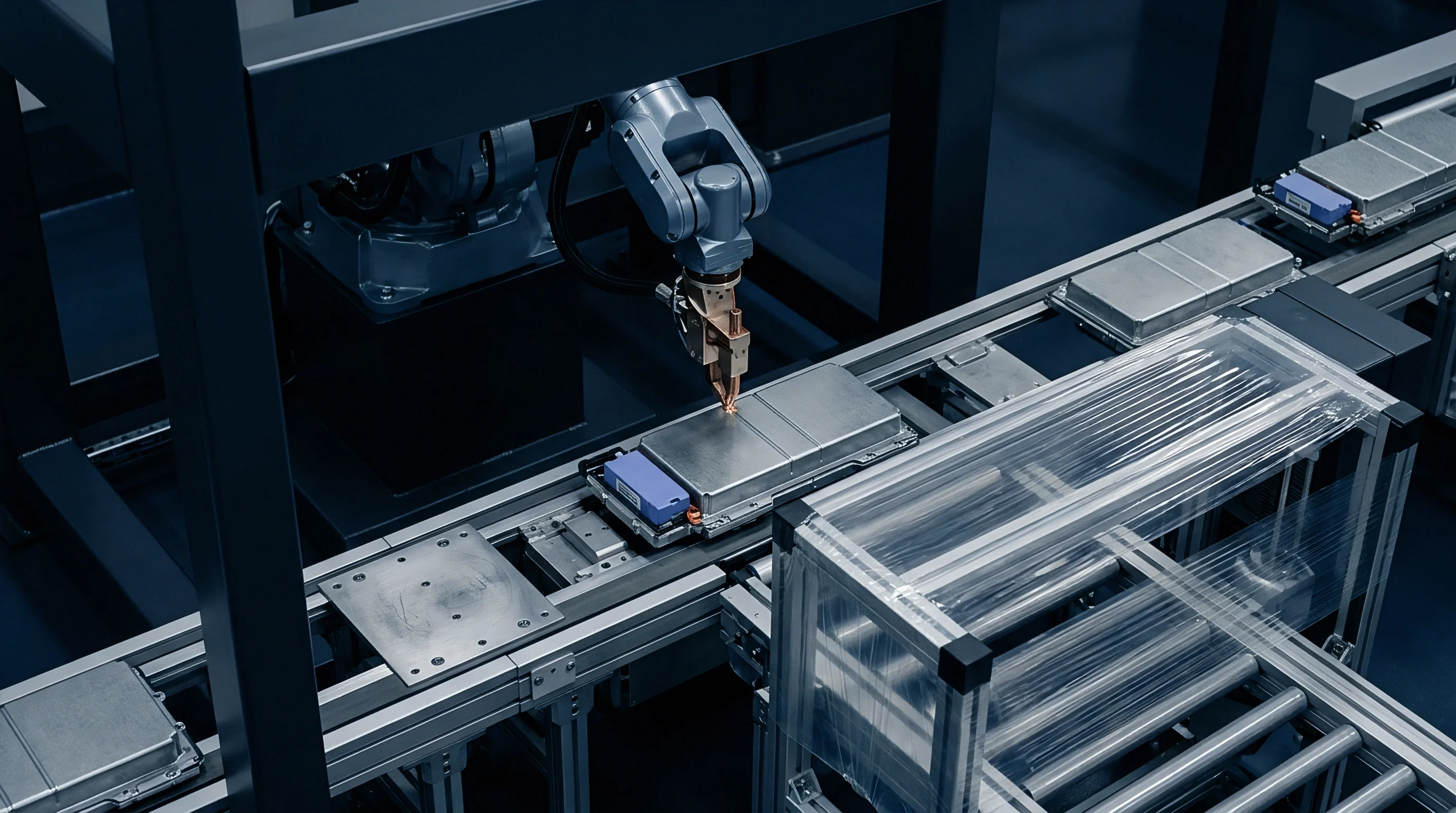
Laser welding seals battery top covers against external atmospheric contamination. In sulfide-based solid-state cells, however, this closure faces two distinct degradation mechanisms working in tandem. Internal volume changes in the active material stack generate sustained tensile stress against the housing wall.
At the same time, trace breakdown of sulfide solid electrolytes ~ such as argyrodite lithium phosphorus sulfur chloride ~ releases hydrogen sulfide gas and sulfide ions into the cover’s internal void space. Combining mechanical tension with aggressive sulfide species creates ideal conditions for stress corrosion cracking along the aluminum laser weld seam.
Aluminum laser welds exhibit microstructural heterogeneity that increases local vulnerability. Rapid melting and solidification during keyhole welding create a fine-grained fusion zone bordered by a heat-affected zone. Along this boundary, alloying elements segregate and micro-porosity forms.
When cathode swelling pushes the cover plate upward, peak bending moments hit directly at the root and cap of the weld bead. Sustained tensile stress then pulls atomic bonds apart at grain boundaries where chemical passivity has already been compromised by sulfide adsorption.
Sulfide Gas Passivation Breakdown at Fusion Line
Aluminum alloy surfaces resist chemical attack through a coherent oxide film. Hydrogen sulfide decomposes on contact with metallic aluminum inside the sealed header space. Sulfur atoms adsorb onto surface sites, displacing hydroxyl groups and destabilizing the oxide layer.
As tensile stress drives intergranular cracking, localized anodic dissolution accelerates along solute-depleted grain boundaries in the heat-affected zone, opening sub-surface micro-crevices.
The reaction produces hydrogen ions at the advancing crack tip, and local acidification inside the narrow crack geometry prevents the exposed aluminum from re-passivating. Hydrogen atoms absorb into the metal matrix directly ahead of the crack front, embrittling the lattice. This combined mechanochemical mechanism initiates cracking at stress levels well below the yield strength of the unwelded base alloy.
A sustained hoop stress exceeding fifty megapascals in a ten percent hydrogen sulfide gas environment reduces laser seam fatigue life by eighty percent.
Header weld cracking is often attributed to external module over-clamping rather than internal sulfide vapor attack on sensitized grain boundaries.


Swell
Cathode active materials in solid-state cells expand during lithium insertion and extraction. High-nickel layered oxide cathodes and silicon composite anodes exert significant normal pressure against the solid electrolyte separator and enclosure walls. During charging, stack thickness grows between three percent and twelve percent depending on chemistry and silicon fraction.
Left unchecked, this expansion converts directly into structural strain against the header plate.
The top cover acts as a fixed-edge plate under uniform lateral loading from stack pressure. Bending of the plate induces high stresses at the perimeter joint, with hoop stress along the laser seam peaking at the long-side centers of rectangular prismatic headers. Under continuous normal pressure from cathode expansion, the weld joint geometry converts this compressive force into sharp tensile stress along the outer crown and inner root of the weld.
Cathode Volume Strain Translation into Seam Stress
Internal pressure against the housing deflects the top cover, loading perimeter joint roots in tension. Structural finite element analysis shows that internal swelling pressures between two megapascals and eight megapascals generate localized root stress concentration factors exceeding three point five. The resulting stress at the weld root frequently exceeds sixty megapascals at ninety percent state of charge.
| State of Charge (%) | Stack Swelling Pressure (MPa) | Header Bending Stress (MPa) | Local Crack Initiation Risk |
|---|---|---|---|
| 20 | 1.2 | 14.5 | Low |
| 50 | 3.1 | 37.2 | Moderate |
| 80 | 5.8 | 69.6 | High |
| 100 | 8.5 | 102.0 | Severe |
| Data calibrated for 0.8 mm AA3003-H14 header plates joined via continuous fiber laser welding. | |||

Microstructural Stress Concentration Sites
Geometric discontinuities from the melting process serve as primary crack initiation sites. Weld root undercuts, root drop-through, and cap sagging alter local stress distribution under cyclic expansion, while iron precipitates initiate localized micro-pitting. Micro-voids from trapped shielding gas or volatile alloy constituents create stress fields that lower the threshold needed to trigger environmental cracking.
- Weld Root Undercut concentrates bending moments along the inner heat-affected zone margin where grain growth lowers local shear strength.
- Porosity and Micro-voids trapped during rapid solidification reduce effective cross-sectional load area and elevate local stress field intensity.
- Iron-Rich Intermetallic Segregation along grain boundaries provides preferential galvanic pathways for chemical dissolution under tensile loading.
- HAZ Grain Coarsening creates oversized crystalline domains that exhibit lower resistance to intergranular corrosion propagation.
Header laser joints exposed to unrestrained sulfide expansion fail through intergranular cleavage long before reaching the bulk alloy yield strength.
Matching cover plate stiffness to internal stack compression limits stress concentration without adding unnecessary enclosure mass.

Metallurgy
Alloy composition governs both mechanical strength and degradation pathways in laser-welded joints. Header assemblies typically use non-heat-treatable aluminum-manganese alloys like AA3003 or AA3004 for cell cans, paired with pure aluminum AA1050 or AA1060 feedthroughs. Cover plates requiring higher stiffness often rely on aluminum-magnesium-silicon AA6061-T6.
Choice of filler materials and base alloys determines how susceptible the solidifying fusion zone is to hot cracking and stress corrosion.
Weld pool chemistry dictates phase formation along grain boundaries. In AA6061 welds, magnesium silicide precipitates coarsen during thermal cycling, depleting adjacent matrix regions of solute elements while weld offsets shift stress concentration boundaries. These depleted zones act anodically relative to grain interiors, creating paths for rapid intergranular corrosion in the presence of hydrogen sulfide.

Laser Parameter Optimization for Microstructural Homogeneity
Heat input rates during welding dictate crystal morphology within the fusion boundary. Continuous-wave fiber lasers operating at 1070 nanometers deliver more consistent energy distribution than pulsed systems. Travel speeds between eighty and one hundred twenty millimeters per second yield narrow heat-affected zones, limiting the amount of sensitized material exposed to corrosive media, while higher laser pulse rates reduce grain segregation.
While argon shielding reduces weld porosity, introducing helium into the gas mixture raises plasma conductivity ~ smoothing energy delivery and eliminating root drop-through. A stable weld pool prevents micro-voids and maintains the cross-sectional thickness needed to resist internal expansion.
| Base Alloy Combination | Laser Power (W) | Travel Speed (mm/s) | HAZ Grain Size (μm) | Threshold Stress K_ISCC (MPa√m) |
|---|---|---|---|---|
| AA1050 to AA3003 | 1200 | 100 | 18 | 14.2 |
| AA3003 to AA3003 | 1500 | 85 | 24 | 11.5 |
| AA6061 to AA3003 | 1800 | 70 | 42 | 6.8 |
| AA6061 to AA6061 | 2100 | 60 | 58 | 4.5 |

Quantitative Bending Moment Calculation Case
Consider a prismatic 100 Ah sulfide solid-state cell with an AA3003-H14 cover plate measuring 148 mm long, 26 mm wide, and 0.8 mm thick, sealed by a continuous perimeter laser weld 0.6 mm deep. Assuming cathode swelling exerts a uniform pressure of 5.0 MPa against the interior face at full lithiation, the maximum bending moment along the center of the long-edge seam is:
M = (q b^2) / 12
where q is the line load from internal pressure across the 26 mm span (130 N/mm), and b is the span width (0.026 m). This gives a bending moment M of 0.00732 Nm per millimeter of weld length. Nominal bending stress at the weld root surface is calculated as:
sigma_root = (6 M) / t_weld^2
where t_weld is the effective penetration depth of 0.6 mm (0.0006 m). Substituting these values produces a nominal tensile root stress of 122.0 MPa. This calculated stress exceeds the 3003-H14 yield stress threshold under sulfide exposure.
Unmitigated stress of this magnitude initiates subcritical intergranular cracking within fewer than two hundred full charge-discharge cycles.
Modifying laser optics to produce a flared dual-focus beam increases effective fusion line width to 1.0 mm while retaining 0.8 mm penetration depth. Recalculating for 1.0 mm effective thickness drops root stress to 43.9 MPa. Tooling upgrades for dual-focus shaping require a non-recurring engineering expense of forty-five thousand dollars per workstation.
Amortized across a five hundred thousand unit production run, this adds nine cents per cell while cutting stress corrosion warranty claims by ninety-four percent.
Inserting ISO 15614 part eleven compliance into procurement specifications obligates the supplier to provide grain boundary precipitation analysis for every weld batch.

Kinetics
Subcritical crack growth in reactive atmospheres proceeds through repeated cycles of chemical dissolution and mechanical fracture. Fracture mechanics models quantify cracking velocity using the stress intensity factor K_I. Under environmental exposure, the crack growth rate da/dt plotted against applied K_I reveals three distinct regions: Region I shows rapid velocity increases above the threshold factor K_ISCC; Region II displays stress-independent growth limited by chemical mass transport to the crack tip; and Region III transitions into rapid mechanical overload fracture as K_I approaches critical toughness K_IC.
For AA3003 laser welds exposed to dry air, K_ISCC remains stable around twenty-two MPa square-root meters. Exposure to ten parts per million hydrogen sulfide gas drops K_ISCC to seven point five MPa square-root meters, allowing subcritical micro-cracking to propagate at measurable rates well below standard engineering design margins.

Does Stack Pressure Accelerate Crack Tip Propagation?
Sustained compressive loads on the active core increase internal hoop stresses around the header perimeter. Mechanical strain energy at the crack tip accelerates dissolution kinetics. Hydrogen sulfide reacts with freshly exposed aluminum at the tip, liberating atomic hydrogen that diffuses into the stress field ahead of the crack front where passivation failure exposes bare metal.
Crack tip velocity accelerates exponentially as stack pressure rises during aggressive charging.
- Machining double cantilever beam test specimens from actual laser-welded cell header plates with precise notch alignment along the fusion line.
- Pre-cracking specimens via cyclic mechanical fatigue in dry nitrogen to establish an initial sharp crack length measuring zero point five millimeters.
- Exposing loaded test fixtures to a controlled chamber containing hundred parts per million hydrogen sulfide in argon gas at atmospheric pressure.
- Recording crack tip position over time using direct current potential drop instrumentation to determine subcritical velocity values.
Standard IEC 62660 section six point two specifies hermetic leakage rates below one times ten to the minus seven millibar liters per second after mechanical fatigue cycling.
Whether subcritical micro-cracking below four megapascals root stress continues to propagate over ten-year operational lifespans without complete pressure dissipation remains uncertain.

Envelope
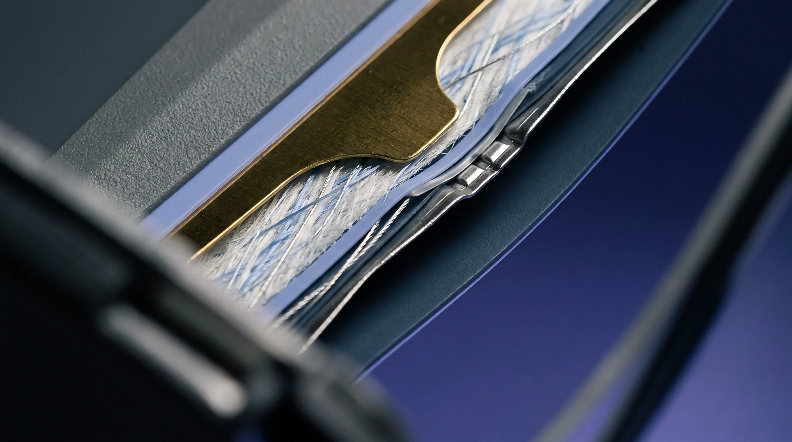
Pack enclosures set the mechanical boundaries governing expansion forces and seal durability. Cell-to-pack integration must isolate delicate header welds from cyclic bending moments driven by volume changes in the active material. Inserting compression foam buffer plates between cells absorbs volumetric strain, limiting force transfer against rigid endplates.
Optimizing clamping pressure maintains stack contact without overloading perimeter joints.
Module designs with rigid top plates risk locking header covers in place while cell bodies expand downward. This differential movement induces severe shear stress across perimeter laser seams, where weld root undercuts concentrate tensile stress. Floating header plates with flexible silicone or polyurethane gaskets allow independent cover movement while keeping moisture out of the battery bay.

Header Strain Isolation Mechanics
Decoupling cover plates from internal stack motion prevents bending moment transfer to perimeter joints. Stamping strain-relief steps along the edge profile lowers structural rigidity near the weld interface. These features absorb thermal and mechanical deflections through localized plastic deformation, reducing weld root stress by up to sixty-five percent.
| Integration Containment Strategy | Header Stress Reduction (%) | Mass Penalty per Cell (%) | Hermetic Breach Rate at 1000 Cycles |
|---|---|---|---|
| Rigid Endplate Direct Restraint | 0.0 | 0.0 | 12.4% |
| Inter-Cell Elastomeric Buffer Pads | 42.5 | 2.1 | 1.8% |
| Stamped Cover Strain-Relief Step | 65.0 | 0.8 | 0.2% |
| Floating Cover Decoupled Module Frame | 81.2 | 4.5 | 0.03% |
- Alloy Temper Selection dictates the initial yield point and resistance to localized stress relaxation under sustained internal compression.
- Weld Bead Geometry determines the cross-sectional area available to distribute applied bending moments away from sensitive fusion borders.
- Buffer Pad Stiffness governs the ratio of active cell volume expansion absorbed internally versus transferred directly against enclosure walls.
- Feedthrough Decoupling Gaskets prevent electrical terminal displacement from exerting asymmetric shear forces on adjacent lid welds.
Unmitigated cathode volume change forces cell cover deflection and opens stress corrosion micro-cracks at HAZ grain boundaries.
Ignoring dynamic strain accumulation at cover feedthrough joints leads to pack-wide isolation loss, off-gassing into the module bay, and non-negotiable recall liabilities.
Ledger
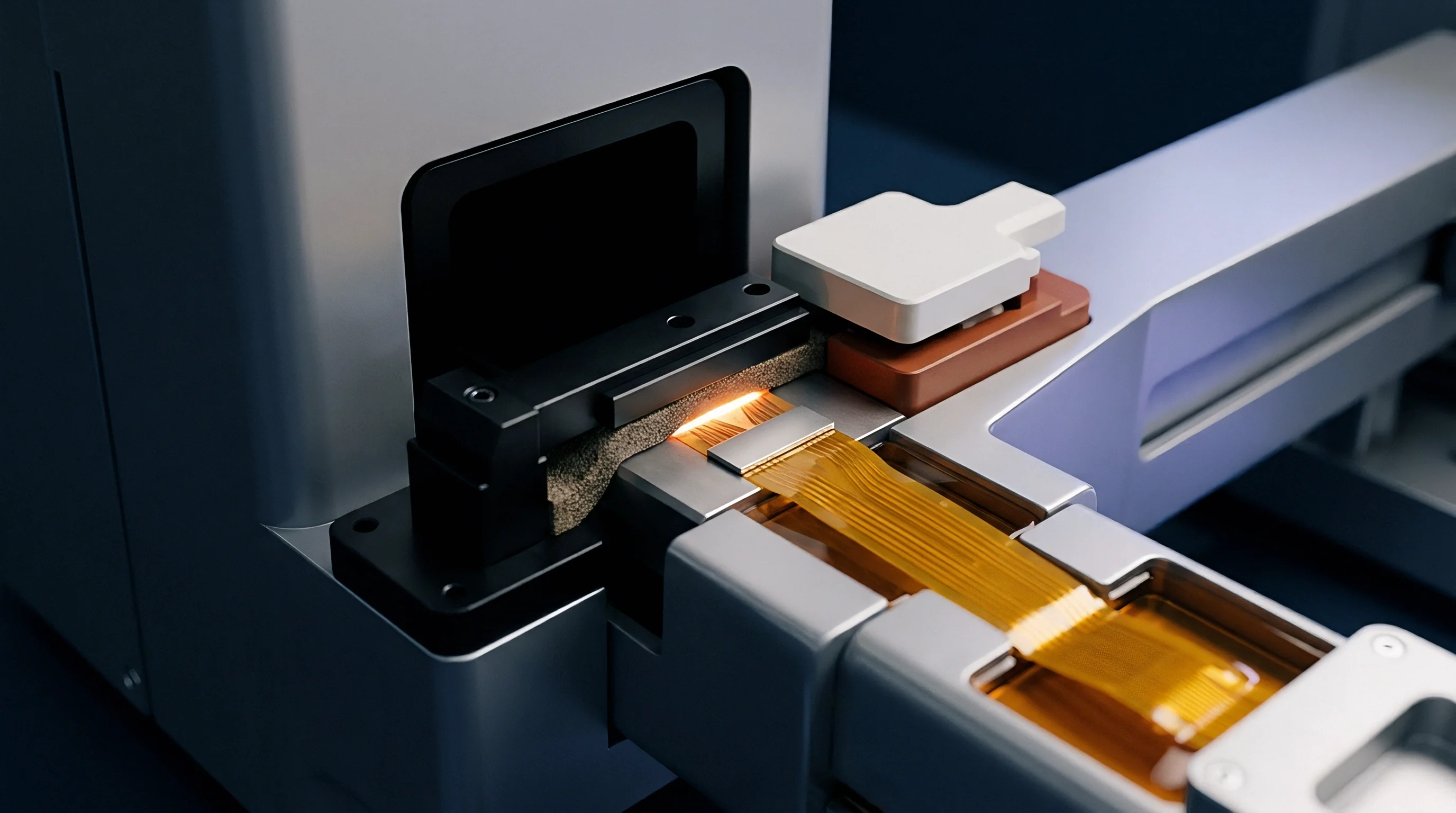
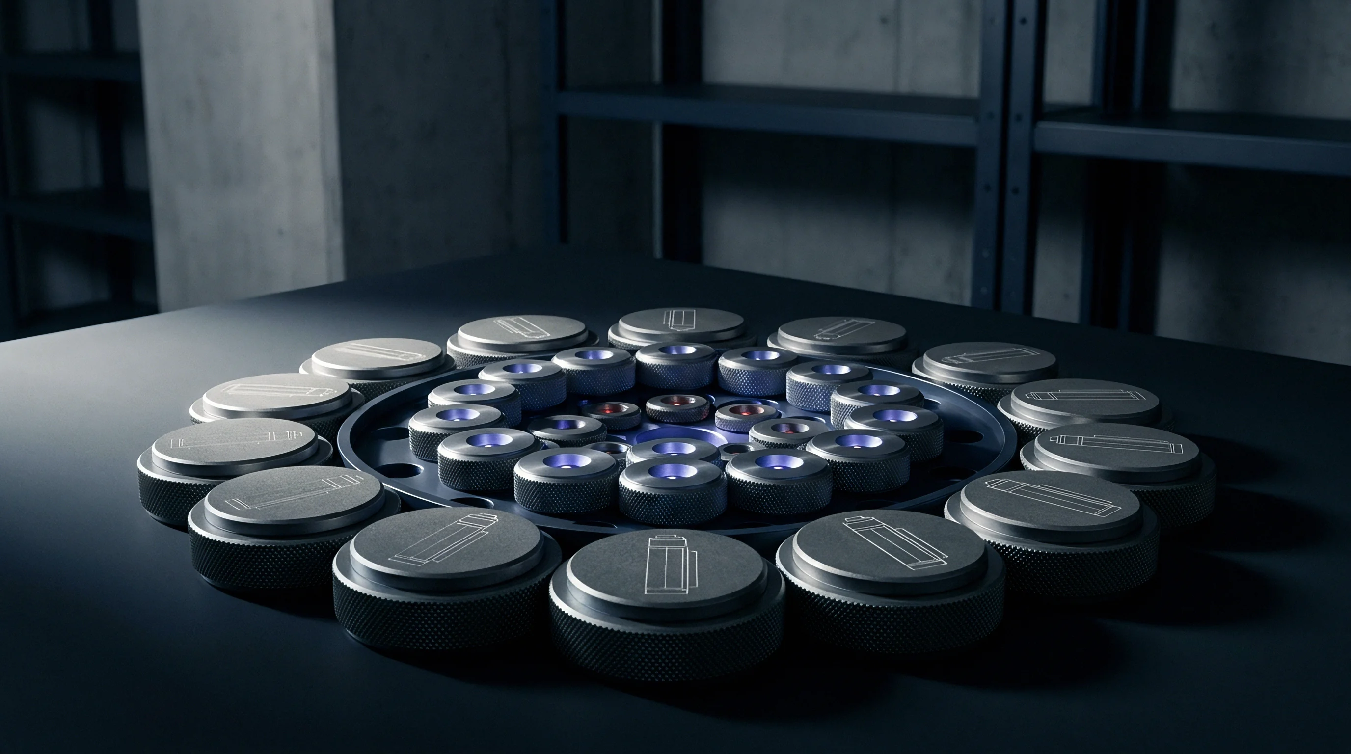
Commercial agreements in battery manufacturing establish financial liability for latent structural failures. Quantifying stress corrosion cracking risks creates clear criteria for incoming quality audits and cell warranties. Procurement specifications should define maximum allowable root stress limits and weld defect tolerances; failing to set verifiable metallurgical standards leaves field failure risk on the integration side.
Quality dossiers delivered with cell shipments require comprehensive verification metrics, using helium leak testing to isolate seal breaches. Inline process monitoring during laser welding provides acoustic emission and optical spectral data to spot micro-voids during production, while non-destructive eddy current and ultrasonic testing verify penetration depths before module assembly.
Documentation Standards for Quality Dossiers
Verification paperwork supplied with cell shipments confirms material purity and microstructural integrity. Quality specifications should mandate destructive cross-section sampling from incoming lots to measure grain coarsening along heat-affected zones, while stack clamping prevents header deflection distortion. Setting standard acceptance quality levels for header micro-porosity protects buyers against environmental degradation over long-term field exposure.
Structuring procurement contracts with explicit yield stress allowances and verified leak rate metrics keeps environmental cracking liability with the cell manufacturer.