Evaluating Stack Pressure Tolerances in Solid Electrolyte Lithium Cells
Maintaining sulfide solid-state cell stack pressure between 3 and 8 MPa suppresses lithium voiding, requiring spring-compliant module packaging.

Interphase
Sulfide-based solid electrolytes operating against metallic lithium anodes require continuous uniaxial pressure between 3 MPa and 8 MPa to prevent interfacial void formation during high-rate discharge. Below 2 MPa, the localized flux of lithium ions during stripping exceeds the plastic flow rate of the metallic lithium, carving vacancies at the solid electrolyte boundary. These micro-voids constrict the current collector contact area, driving up local current density at remaining contact points and initiating rapid dendrite propagation during subsequent charge cycles.
Conversely, oxide-based garnets such as lithium lanthanum zirconium oxide tolerate negligible bulk plastic deformation, demanding initial room-temperature assembly pressures near 5 MPa to offset surface roughness while risking catastrophic intergranular fracture if mechanical load exceeds 15 MPa.
The mechanical stress state within a solid-state cell directly governs ionic transport kinetics across the heterojunction. When lithium ions strip from the anode during discharge, vacancies accumulate unless the surrounding metal creeps into the depleted volume. Lithium exhibits a low yield strength near 0.8 MPa at room temperature, yet rate-dependent strain hardening alters its deformation response under dynamic cycling.
Higher C-rates demand proportionally higher external compression to ensure the creep rate matches the volumetric rate of metal removal.
Applying 5 MPa continuous stack pressure at 25 degrees Celsius maintains intimate interfacial contact across sulfide-lithium interfaces at discharge rates up to 3 milliamp-hours per square centimeter.
Polymer-ceramic composite electrolytes present a distinct electro-chemo-mechanical profile. At operating temperatures above the glass transition point of the poly(ethylene oxide) matrix, the soft polymer fills interfacial microscopic valleys under modest loads of 0.1 MPa to 0.5 MPa. However, the lower shear modulus of pure polymer phases reduces their intrinsic resistance to lithium dendrite penetration, forcing engineers to balance mechanical confinement against structural enclosure weight.
Yield Mechanics at the Anode Boundary
Deformation behavior at the solid electrolyte interface determines whether a cell maintains steady capacity or suffers abrupt short circuits. Metallic lithium flows plastically under sustained stress, but its behavior under constraint inside a rigid cell stack differs from unconstrained uniaxial compression testing. Solid electrolyte surface asperities concentrate stress locally, producing localized pressure gradients that reach several times the average applied stack pressure.
Microstructural surface roughness on polished ceramic separators creates stress risers. When an average load of 5 MPa applies to a ceramic plate with an arithmetic mean roughness exceeding 0.2 micrometers, peak contact points experience localized stress above 30 MPa. These localized pressure peaks induce creep in the adjacent lithium, filling valleys over a duration dictated by the strain-rate sensitivity exponent of the anode metal.
If the initial clamping pressure falls short of the plastic yield threshold across real contact areas, residual interfacial gaps persist, serving as focal points for electric field concentration.
Temperature shifts modify this mechanical equilibrium significantly. Operating a cell at 0 degrees Celsius elevates the yield strength of lithium metal, slowing plastic flow and increasing the minimum threshold pressure required to prevent vacancy formation during discharge. Pack designers integrating solid-state cells into ambient-temperature environments must account for this kinetic slowdown by either elevating steady-state stack compression or introducing thermal management protocols that restrict high-rate discharge until internal temperatures cross 20 degrees Celsius.
An unresolved question remains whether non-uniform creep rates across polycrystalline solid electrolyte grain boundaries can be completely homogenized using variable hydraulic clamping without inducing localized ceramic shear failure.

Swell
Volumetric strain during electrochemical cycling imposes dynamic loading requirements on the module containment structure. Solid electrolyte lithium cells utilizing pure silicon or silicon-graphite composite anodes exhibit breathing amplitudes between 8 percent and 22 percent across a full state-of-charge sweep. Even anode-free configurations, where lithium plates directly onto a thin-film current collector during charge, experience a linear thickness expansion of approximately 0.5 micrometers for every milliamp-hour per square centimeter of deposited capacity.
Unconfined dynamic expansion degrades cell performance rapidly. Without external elastic confinement, the continuous dimensional change destabilizes internal interfaces, fracturing composite electrolyte matrices and tearing current collector foils. Housing solid-state cells within rigid, zero-clearance enclosures leads to exponential pressure accumulation during charging, pushing internal stack stress past 25 MPa and triggering structural failure of module end plates or crushing active ceramic layers.
| Electrolyte Chemistry Family | Minimum Retention Pressure (MPa) | Maximum Structural Pressure (MPa) | Interface Strain per Cycle (%) | Primary Failure Mode Under Low Load |
|---|---|---|---|---|
| Sulfide (LPSCl / Argyrodite) | 3.0 | 10.0 | 4.2 to 8.5 | Interfacial vacancy formation and dendrite growth |
| Oxide Garnet (LLZO) | 4.5 | 15.0 | 0.8 to 2.1 | Contact loss and rapid impedance growth |
| Polymer-Ceramic Composite | 0.2 | 2.5 | 6.0 to 14.0 | Delamination and filament penetration |
| Halide (Li3YCl6 derivatives) | 1.5 | 6.0 | 3.1 to 5.5 | Micro-void accumulation at cathode particles |
Managing dynamic pressure sweeps requires mapping the load profile across the entire operating state-of-charge band. As lithium ions transfer from cathode to anode during charging, the cell stack thickens, compressing the internal spring mechanism of the module. During discharge, the volume contracts, reducing force on the stack.
The ideal containment system maintains stack stress strictly within the green band defined by the minimum pressure for void prevention and the maximum pressure for ceramic integrity.
Transient Pressure Profiles during High-C Charging
Dynamic compression behavior diverges markedly under fast-charging conditions. Rapid lithium deposition generates localized ion accumulation before stress-driven diffusion can redistribute the metal evenly across the current collector plane. This localized accumulation creates transient pressure spikes that localized piezoresistive arrays register as focal points up to 40 percent higher than the average bulk pressure measured at the end plates.
These local pressure spikes accelerate cathode particle cracking in high-loading nickel-rich transition metal oxide layers. When composite cathodes contract during lithium extraction while the anode expands, internal shear stresses develop across the solid electrolyte interface. If the external spring system lacks mechanical compliance, the combined effect of active layer expansion and transverse shear stress fractures delicate solid electrolyte networks embedded inside the cathode matrix.
A compliance spring system with non-linear load-deflection characteristic offsets volumetric cell expansion while holding stack stress within a 2 MPa operational window across full state of charge.
Thermal expansion compounds electro-chemo-mechanical swelling. Aluminum module enclosures expand at 23 parts per million per degree Celsius, whereas oxide ceramic electrolyte stacks expand at less than 10 parts per million per degree Celsius. A temperature rise from 20 degrees Celsius to 60 degrees Celsius reduces structural preload if the enclosure housing expands faster than the cell stack, dropping active interface pressure below the threshold required to suppress void formation.
Stack compression must increase continuously as cell impedance rises over operational life to compensate for surface area loss from micro-cracking.

Platen
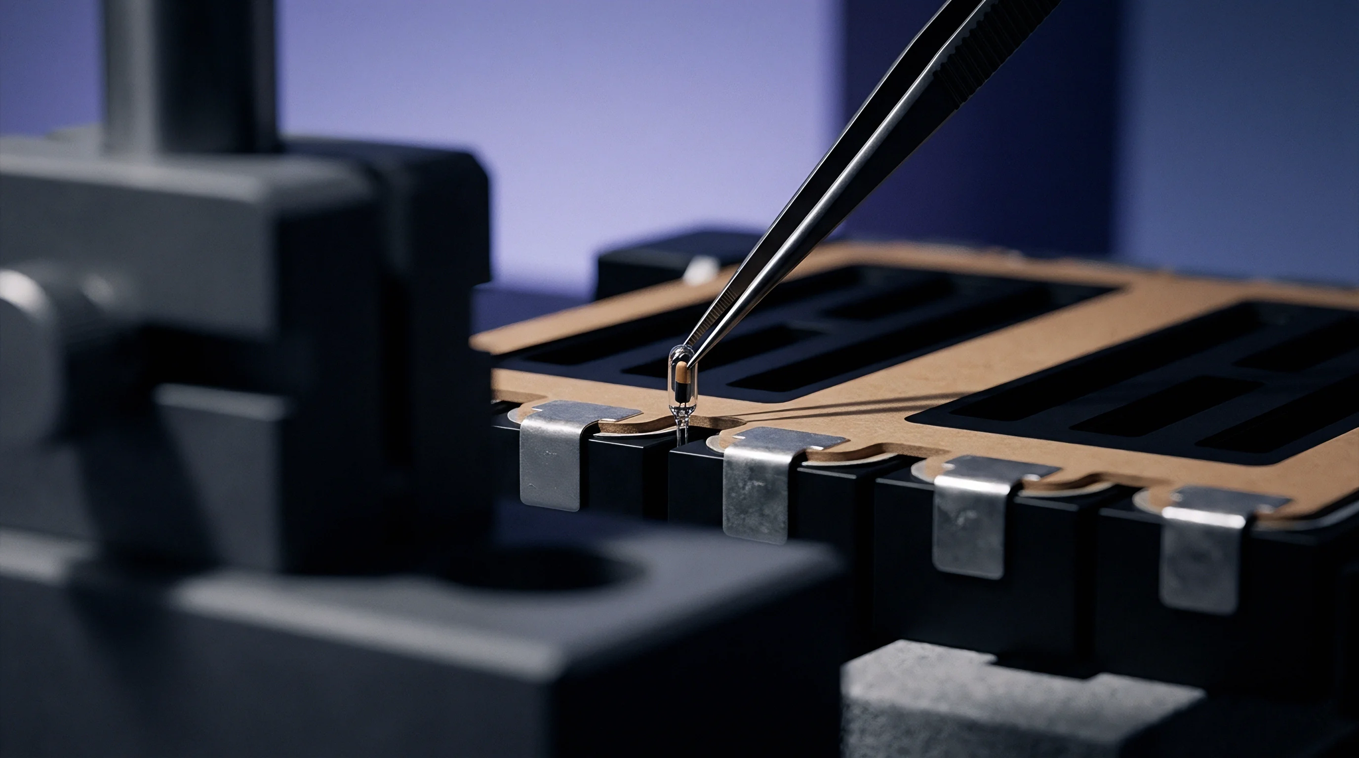
Translating electrochemical pressure demands into durable pack architecture requires precision compression fixtures. Module platens must maintain surface flatness within 0.05 millimeters across their entire area under loads reaching 50 kilonewtons. Flexure in structural end plates redistributes force toward module edges, leaving cell centers under-compressed and highly susceptible to premature capacity fade driven by interfacial delamination.
Designing compression hardware involves balancing structural mass, spring compliance, and dimensional manufacturing tolerances. Rigid clamping using fixed tie rods fails because it provides zero compliance; normal manufacturing height variations across a 10-cell pouch stack (typically plus or minus 0.3 millimeters per cell) translate into severe over-compression or total loss of preload. Engineers implement spring-loaded or elastomeric compliance elements to absorb cell-to-cell thickness tolerances and dynamic cycling strain.
The sequence below walks the mechanical engineering procedure for dimensioning a spring-loaded module platen assembly under structural tolerances:
- Establish minimum active force based on the low-temperature stripping threshold of the selected sulfide electrolyte cell format, setting the absolute baseline at 3.5 MPa across the minimum pouch contact area.
- Determine total stack height variation by summing individual cell thickness manufacturing tolerances, thermal expansion ranges across minus 30 to 65 degrees Celsius, and maximum end-of-life irreversible swelling allowances.
- Calculate required spring stiffness by dividing the maximum allowable pressure increase (typically 3.0 MPa above baseline) by the total accumulated dimensional stack deflection.
- Select spring element geometry using Belleville washer stacks arranged in series-parallel configurations or customized wave springs that fit within module frame boundaries.
- Verify platen structural deflection using finite element analysis under maximum end-of-life load to confirm surface planarity stays within 0.03 millimeters.
- Apply thermal expansion compensation factors to tie-rod structural materials to prevent preload relaxation at elevated operating temperatures.
Belleville washers offer high load capability within compact axial spaces, making them suitable for high-pressure oxide and sulfide cells. Wave springs provide longer deflection strokes at lower force increments, fitting the narrower pressure windows of polymer composite cells. Elastomeric foam pads provide uniform surface pressure distribution but suffer from long-term stress relaxation and thermal degradation over automotive lifespan requirements.
| Compliance Mechanism Type | Stiffness Control Precision | Long-Term Creep Resistance | Mass Penalty per kWh | Volumetric Overhead (%) |
|---|---|---|---|---|
| Belleville Washer Array | High (+/- 5%) | Excellent (< 2% over 10 years) | 0.85 kg | 4.2 to 6.0 |
| Nested Wave Springs | Moderate (+/- 8%) | Good (< 4% over 10 years) | 0.62 kg | 3.5 to 5.0 |
| Closed-Cell Silicone Foam | Low (+/- 18%) | Poor (> 25% over 3 years) | 0.15 kg | 1.8 to 2.5 |
| Hydraulic Bladder System | Very High (+/- 2%) | Excellent (Active regulation) | 1.40 kg | 7.0 to 9.5 |

Tolerance Stack-Up Analysis in Module Engineering
Accumulated dimensional variations across cell stacks directly alter the applied mechanical preload. In a module comprising 12 series-connected pouch cells, individual component height variations stack up according to root-sum-square statistical models. A single pouch cell with a nominal thickness of 5.00 millimeters carries a manufacturing tolerance of plus or minus 0.08 millimeters.
The 12-cell stack yields a statistical variance of plus or minus 0.28 millimeters at initial assembly.
If the compliance spring system features a high spring rate of 20 kilonewtons per millimeter, a stack height variation of 0.28 millimeters creates an initial force uncertainty of 5.6 kilonewtons. Across a cell surface area of 200 square centimeters, this deviation changes initial stack pressure by 0.28 MPa. While this variation appears small, adding thermal expansion strain and life-cycle volume growth pushes stack force beyond the upper design limit of the end plates, causing structural distortion.
Machined aluminum end platens must incorporate ribbing structures designed to resist bending moments under continuous load. Unreinforced platens bow outward under central pressure loads, causing edge-concentrated pressure profiles across pouch surfaces. Edge over-compression accelerates local degradation, tears separator frames, and initiates premature shorting along pouch borders.
Designing a compression system without accounting for long-term stress relaxation in elastomeric pads causes the stack pressure to drop below the minimum void-suppression threshold within 18 months, triggering irreversible interfacial impedance growth and voiding the pack warranty.

Worked Fixture Calculation under Thermal and Lifetime Strain
Consider a solid-state module requiring a constant active pressure window between 4.0 MPa and 7.0 MPa across its full life cycle. The module houses a single stack of 10 solid-state pouch cells. Each cell has an active surface area of 250 square centimeters (0.025 square meters) and a nominal uncompressed thickness of 6.00 millimeters.
The target active force range across the cell area equals 100 kilonewtons at 4.0 MPa and 175 kilonewtons at 7.0 MPa, establishing a maximum allowable force span of 75 kilonewtons.
Dimensional expansion inputs are defined as follows: manufacturing thickness tolerance is plus or minus 0.05 millimeters per cell (total stack statistical variation of plus or minus 0.16 millimeters); reversible electrochemical swelling equals 0.30 millimeters per cell across state-of-charge sweep (3.00 millimeters total stack deflection); irreversible lifetime swelling accounts for 0.10 millimeters per cell (1.00 millimeter total stack deflection); operational thermal expansion delta adds 0.24 millimeters across a 50-degree Celsius temperature range. Summing these worst-case deflection contributions yields a total mechanical stack stroke requirement of 4.40 millimeters.
To determine the maximum allowable spring rate for the compliance system, divide the 75 kilonewtons force span by the 4.40 millimeters total deflection stroke. This calculation yields a maximum allowable spring stiffness of 17.05 kilonewtons per millimeter for the entire module spring array. If four spring locations are implemented on the tie rods, each individual spring stack must possess a stiffness no greater than 4.26 kilonewtons per millimeter while surviving a peak mechanical load of 43.75 kilonewtons without fully compressing to its solid height.

Gage
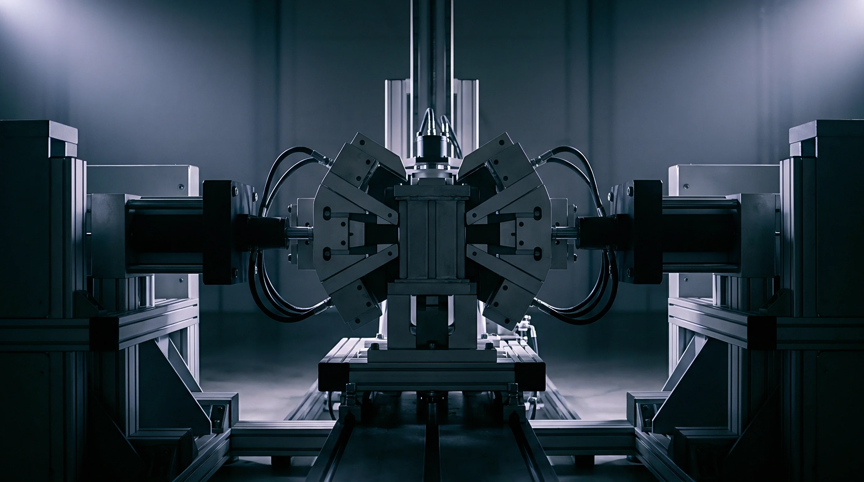
Accurate verification of internal stack pressure profiles inside sealed cell enclosures presents significant metrological challenges. External load cells attached to testing platens capture aggregate normal forces but miss internal pressure gradients caused by localized thickness variations, electrode edge burrs, or uneven active layer distribution. Evaluating solid-state cell pressure requirements demands high-resolution, thin-film instrumentation integrated directly into qualification test rigs.
Tactile piezoresistive pressure sensors inserted between cell surfaces provide two-dimensional spatial mapping of stress distribution. These sensor arrays feature active sensing points down to 0.5 millimeter spatial resolution, allowing test engineers to detect localized high-pressure points and edge effects before cycling begins. However, inserting sensor substrates thicker than 50 micrometers introduces local strain distortions that alter the true pressure field inside cell stacks.
Integrating 25-micrometer tactile piezoresistive matrix arrays reveals that localized edge pressure peaks exceed average end-plate load readings by more than 35 percent during high-state-of-charge cell swelling.
Calibrating sensing hardware under dynamic temperature and load conditions remains essential for generating reliable quantitative data. Piezoresistive films exhibit temperature-dependent sensitivity drift, requiring real-time thermal compensation when mapping pressure during high-rate charge cycles or elevated-temperature storage tests. Load frame instrumentation must decouple structural fixture friction from true stack reaction force using floating multi-axis load cells.
In-situ acoustic time-of-flight measurements provide a non-destructive method for monitoring internal stack pressure changes during operation. Ultrasonic pulses transmitted through the cell stack shift in velocity and amplitude as internal mechanical stress changes density and elastic moduli across solid interfaces. Correlating acoustic wave speed variations with calibrated external force measurements enables real-time pressure estimation inside sealed production packs without inserting physical sensors that disrupt cell interfaces.
What Pressure Band Prevents Dendrite Penetration?
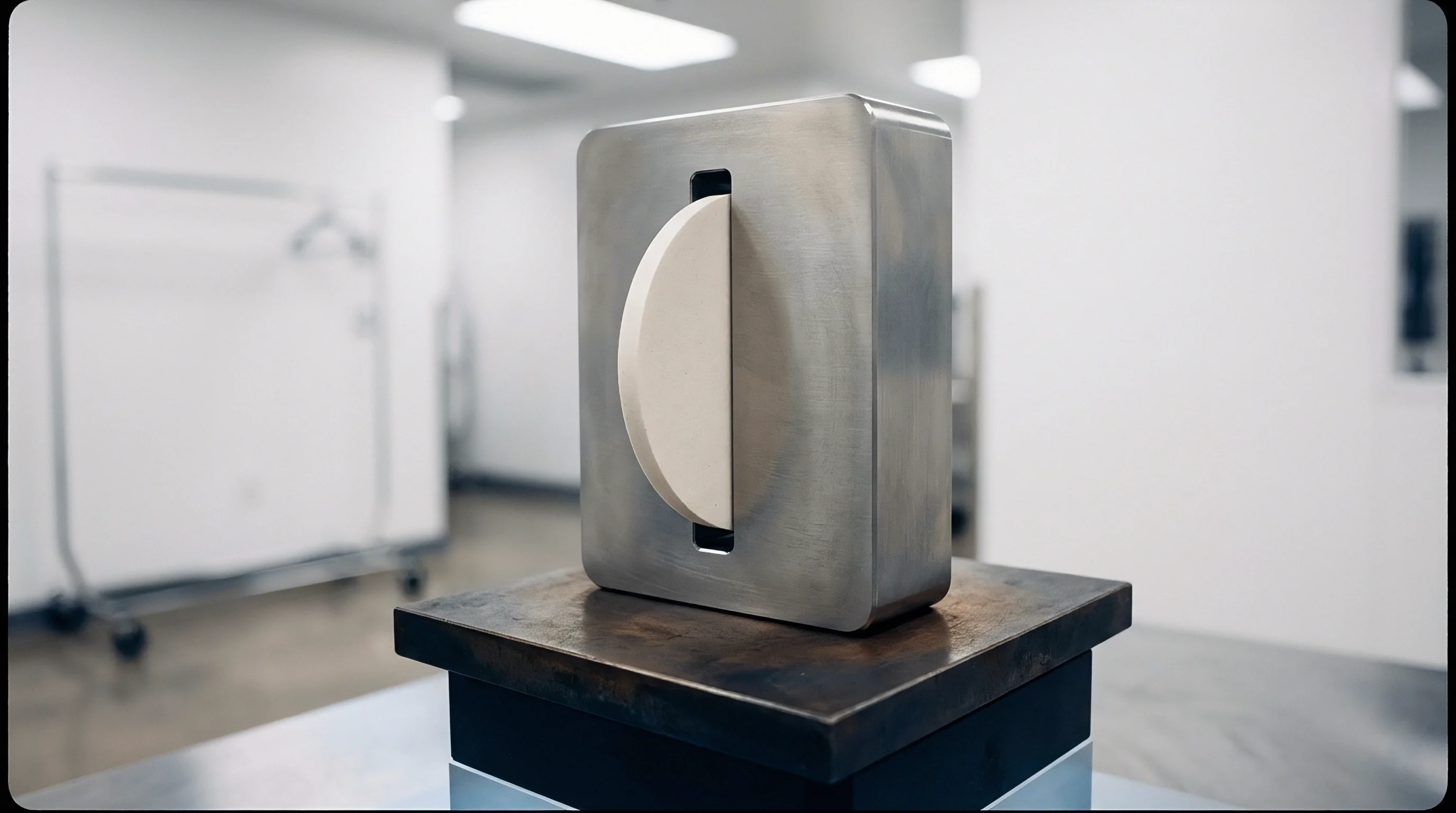
Suppressing lithium dendrites in sulfide solid electrolytes requires maintaining localized compressive stress above the critical yield threshold of metallic lithium across all operating temperatures. Experimental validation shows that maintaining a baseline pressure band between 4.0 MPa and 6.0 MPa prevents lithium penetration through 100-micrometer thick electrolyte separators at current densities up to 4 milliamp-hours per square centimeter at 25 degrees Celsius. Falling below 3.0 MPa allows lithium filaments to propagate through intergranular boundary channels, causing short circuits within fewer than 50 cycles.
Elevating stack pressure beyond 10.0 MPa does not improve dendrite resistance further; instead, excess pressure accelerates creep of metallic lithium through porous separator regions, increasing the risk of mechanical short circuits. Qualification testing protocols must map this electro-chemo-mechanical window across temperatures ranging from minus 20 degrees Celsius to 60 degrees Celsius to define safe operating boundaries for battery management system pressure alarms.
A list of critical failure signatures observed during pressure verification testing includes:
- Interfacial delamination drop marked by rapid impedance growth during discharge when local stack compression drops below 1.8 MPa.
- Localized pressure spike caused by uneven lithium plating along cathode edges where local stress rises above 12.0 MPa during fast charging.
- Thermal creep relaxation evidenced by a continuous drop in baseline assembly force exceeding 15 percent following extended elevated-temperature storage.
- Structural ceramic fracture signaled by abrupt, localized drops in pressure accompanied by immediate internal micro-shorting across oxide separator plates.
Suppliers frequently claim that laboratory test cells achieve 1,000 cycles at 0.1 MPa ambient pressure, omitting the detail that these bench trials utilized ultra-thin liquid-wet interface layers or microscopic single-crystal separators that cannot be mass-produced on commercial roll-to-roll manufacturing lines.

Covenant
Commercial contracts and technical specifications for solid electrolyte lithium cells must explicitly define mechanical stack pressure parameters alongside traditional electrical metrics like capacity, energy density, and internal resistance. Purchasing cell lots without defining required operational pressure envelopes leaves buyers liable for module-level structural failures, rapid capacity degradation, and voided performance guarantees.
Cell specifications must declare both initial assembly compression requirements and maximum allowable dynamic pressure limits over lifespan. A rigorous Request for Quotation (RFQ) dictates the allowable pressure window across all operating states of charge, temperatures, and cycle milestones. Defining these boundaries fixes financial and operational liability between cell manufacturers and pack integration houses.
Key technical clauses required inside solid-state cell procurement documentation comprise:
- Initial Assembly Preload Specification establishing mandatory room-temperature mechanical load range (for example, 4.0 MPa plus or minus 0.3 MPa) required during pack production.
- Dynamic Reversible Swelling Limit capping maximum permissible thickness expansion per cell across zero to 100 percent state-of-charge sweep at a maximum of 5 percent of nominal cell height.
- End-of-Life Irreversible Swelling Allowance setting the upper limit for permanent cell thickness growth after 1,500 full equivalent cycles at no more than 8 percent above initial compressed thickness.
- Pressure-Dependent Warranty Threshold Clause stipulating that cell warranty commitments remain valid provided module containment structures keep active stack stress strictly between 2.5 MPa and 8.0 MPa throughout operational life.
Standard compliance testing frameworks such as UN 38.3 for dangerous goods transportation and IEC 62619 for industrial energy storage must be executed with cells secured inside representative mechanical compression fixtures. Conducting mechanical shock, drop, or vibration testing on uncompressed solid-state pouch cells yields false pass results or causes immediate internal delamination that invalidates electrical safety data.
The landed cost of solid-state pack architecture reflects structural compression hardware expenses alongside active chemical costs. High-pressure sulfide and oxide cells demand precision-machined end platens, high-tensile steel tie rods, and specialized Belleville spring arrays that add 12 to 18 USD per kilowatt-hour in module mechanical tooling and raw material costs. Lower-pressure polymer composite cells reduce structural hardware overhead to 3 to 5 USD per kilowatt-hour, shifting the economic calculation for mass-market vehicle applications.
Standard supply terms specify that any capacity fade exceeding 20 percent prior to 1,500 cycles will be fully covered under seller warranty, provided the buyer presents logged pack sensor data demonstrating continuous adherence to the specified 4.0 to 7.0 MPa operational pressure window.