Mechanical Clamping Compression Mechanics under Cyclic Lithium Cell Swelling
Controlled mechanical clamping combines rigid platen bracing with elastomeric cushions to constrain cyclic lithium cell swelling stress between 0.2 and 0.5 MPa.


Dilation
Load cells placed across a 280-Ah prismatic lithium iron phosphate test block show a static baseline of 0.32 MPa at 30 percent state of charge. Driven to 100 percent, the platen monitors register 0.68 MPa while cavity dimensions remain fixed. That pressure surge comes down to internal electrochemical swelling: host lattices expand as lithium ions fill interstitial sites in the jelly roll.
How much a cell breathes over a cycle depends on the active material, the electrode formulation, and the separator’s porosity.
The graphite lattice expands roughly 10 to 13 percent along its c-axis when moving from bare carbon to fully lithiated stages. In fresh prismatic hard-case cells, that crystallographic shift shows up externally as a 1.5 to 3.0 percent thickness increase per charge cycle. Pouch cells, lacking rigid aluminum sidewalls, swell 4.0 to 9.0 percent under the same operating cycle.
A 280-Ah lithium iron phosphate prismatic cell expands by 1.8 percent in thickness across a single 1C charge cycle at 25 degrees Celsius.

Reversible Breathing and Irreversible Growth
Anode particles expand during lithium insertion and contract when the ions leave. This reversible volume change tracks state of charge in a mechanical wave that repeats cycle after cycle. Cathodes behave differently.
Layered nickel-manganese-cobalt oxides contract non-linearly by 1.5 to 2.5 percent at high delithiation, partially offsetting anode growth, while lithium iron phosphate undergoes an overall unit cell volume shrinkage of approximately 6.5 percent upon complete delithiation. Measurable cell dilation is simply the net result: graphite expanding while the olivine or oxide cathode contracts.
Irreversible growth builds alongside this cyclic breathing. Every cycle consumes a fraction of active lithium to repair passivating solid electrolyte interphase films on the negative electrode, depositing porous, inorganic breakdown products that permanently wedge particle gaps apart, while dead lithium forms unreactive crusts. In high-nickel cathodes, micro-cracks expose fresh surfaces that consume more electrolyte, dissolve transition metals, and leave behind additional solid debris.
Over 3,000 cycles, this irreversible swelling pushes cell thickness up 6 to 12 percent, turning compliant containment into a rigid hydraulic lock.
Electrode Phase Shifts and Crystallographic Strain
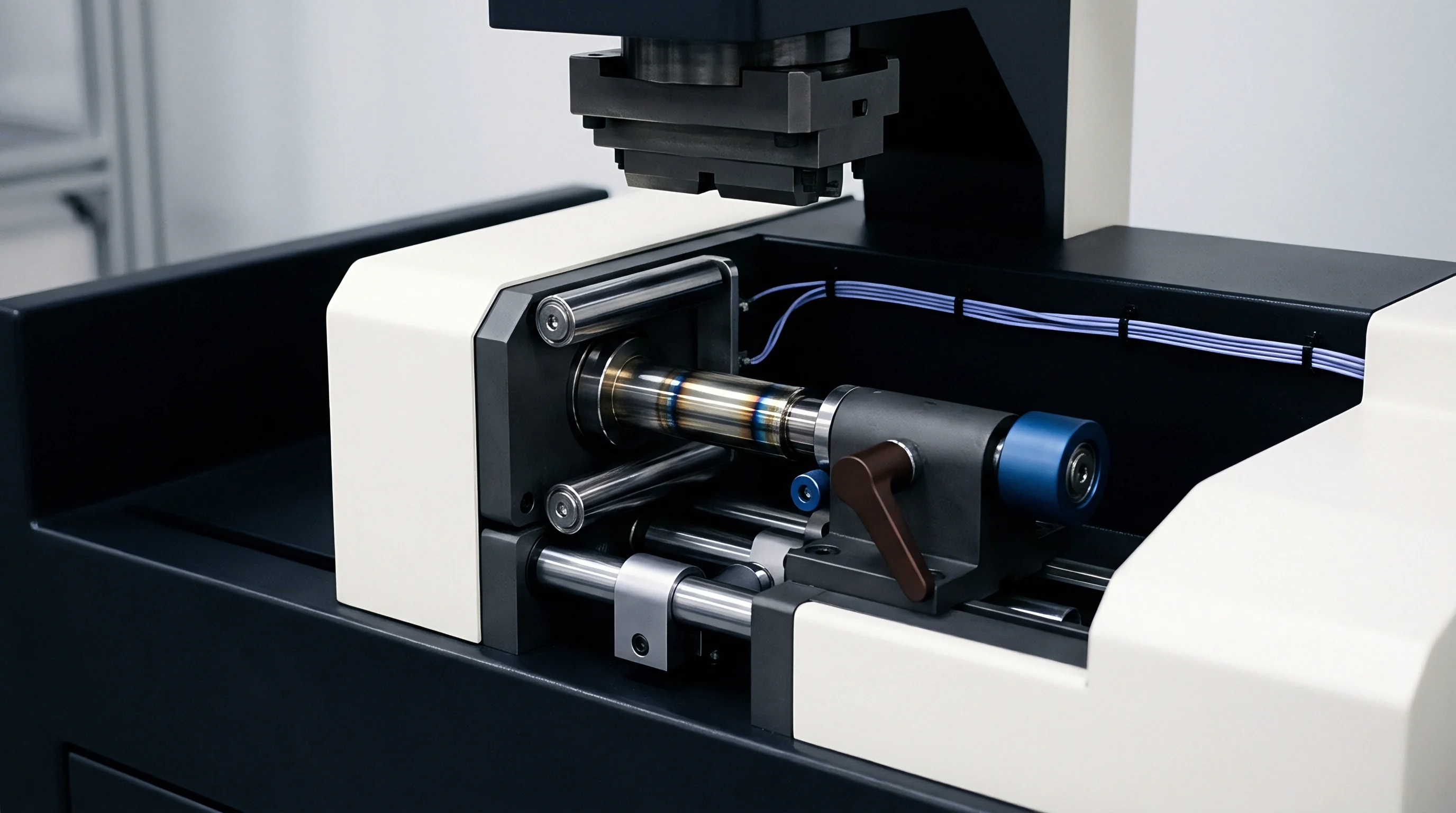
Graphite undergoes distinct staging transitions that widen interlayer spacing from 0.335 nanometers to 0.370 nanometers at full stoichiometry. Stepping through dilute stage 1′, stage 4, stage 3, stage 2, and stage 1 produces visible steps in the cell’s thickness curve. Silicon blends swell far more aggressively: blending five to ten weight percent silicon into graphite boosts specific capacity, but raw silicon particles expand over 280 percent at full lithiation.
Left unchecked, that expansion crushes neighboring carbon, tears binder networks apart, and accelerates electrolyte consumption.
Whether lattice expansion can ever fully decouple from solid electrolyte interphase growth across decade-long stationary operating lifespans remains an open thermodynamic problem for next-generation chemistries.

Platen
End plates carry the cumulative reaction load of an entire constrained module. When twenty-four or thirty-six cells swell together, total thrust against the outer plates reaches tens of kilonewtons. Under that central pressure, thin platens bow outward, concentrating stress around the perimeter while starving the center of the cell face of compression.
Although steel platens resist flexure well, extruded aluminum is often favored to save mass ~ even though aluminum has only one third the elastic modulus of structural steel. Matching the bending stiffness of a thin steel stamping in aluminum requires heavy ribbing or double-walled profiles. Where compression across a cell becomes uneven, lithium plates out as metallic dendrites in the low-pressure zones where interfacial impedance climbs, speeding capacity fade and inviting thermal hazards during fast charging.
Thick end plates add parasitic pack mass while thin plates bow under central pouch swell.
Bending Deflection across Cell Face Spans
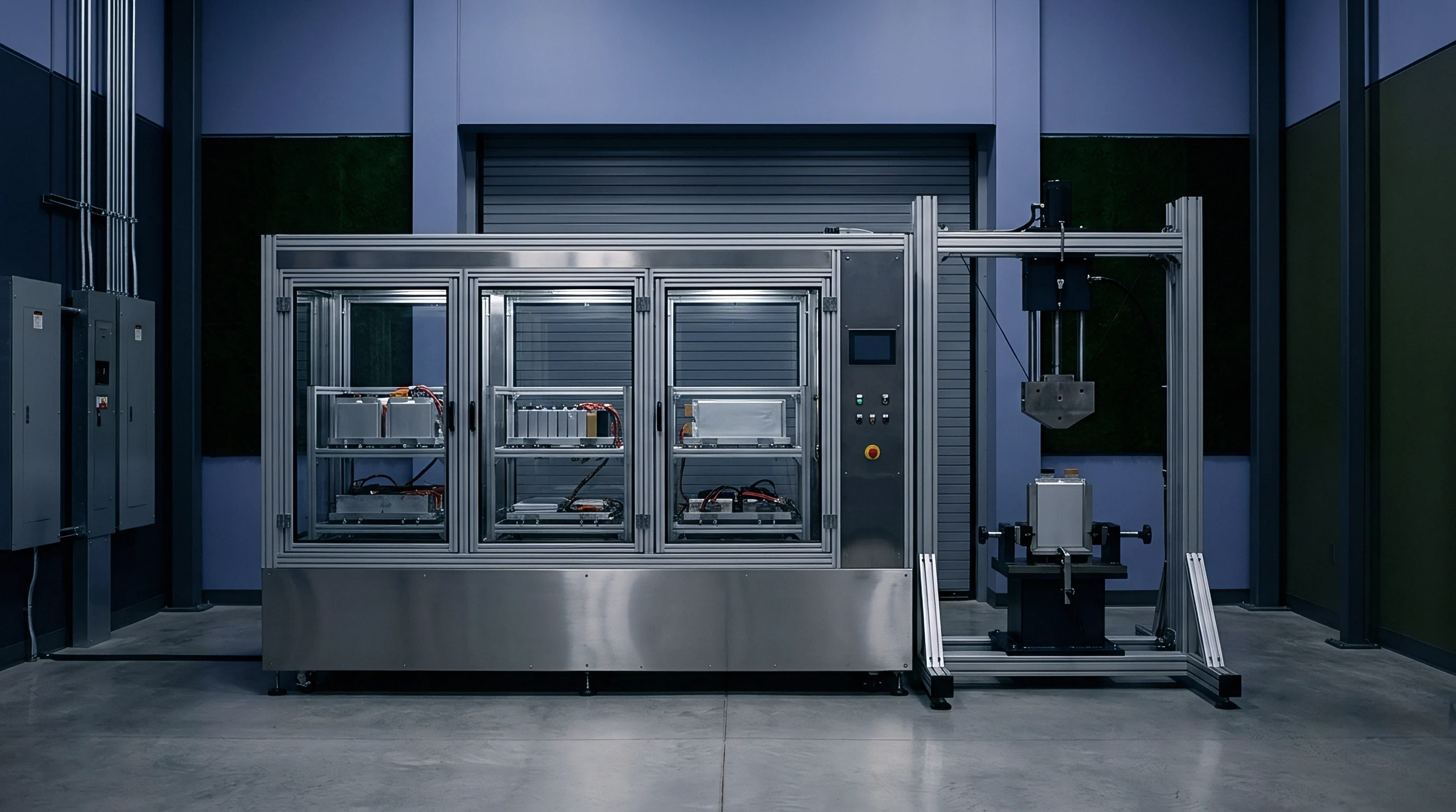
Maintaining uniform compression across the active area prevents current crowding in the center. In structural terms, platens function as loaded plates or beams supported by side tension members. At maximum swelling, central deflection needs to stay under 0.20 millimeters across a standard 174-millimeter cell face width.
Anything past that produces a parabolic pressure trough, dropping the center of the electrode stack to 0.05 MPa while clamping the outer edges at 0.80 MPa.
Platen design flaws lead to distinct mechanical failures inside constrained modules:
- Interfacial delamination occurs across central electrode areas where contact pressure falls below the threshold needed to preserve physical contact with the current collector foil.
- Localized separator crush develops along platen perimeter flanges where excessive clamping stress collapses micropores and restricts lithium ion transport.
- Tie rod necking manifests when thermal expansion combines with cyclic swelling to exceed the tensile yield limit of lateral threaded fasteners.
- Weld seam shear tears the side cover seams of thin aluminum module trays under cyclic breathing fatigue.
Structural Tie Rod and Enclosure Boundary
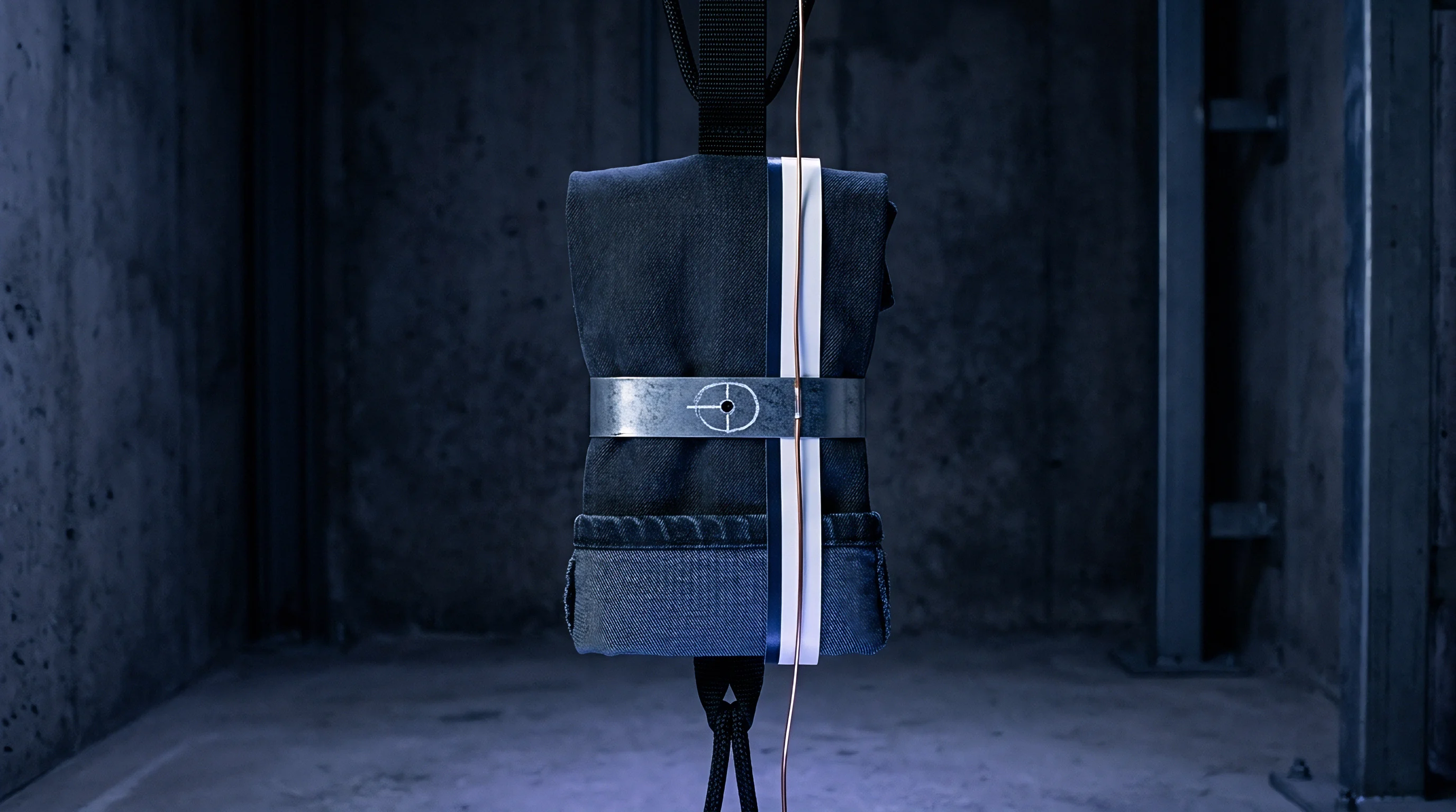
Side bands and perimeter tension members close the structural loop around stacked cells. Corner bolts, cold-rolled stainless tie rods, or woven high-strength steel straps tie opposing platens together to carry tensile loads and hold cavity length fixed over operating life. The rigidity of these tension members sets the overall compliance of the pack structure.
Thermal expansion differences compound the problem. Aluminum cell cans, steel platens, and copper busbars expand at noticeably different rates across the operating range from minus 20 degrees Celsius to 45 degrees Celsius. An aluminum chassis expands at roughly 23 micrometers per meter per kelvin, compared to just 12 micrometers per meter per kelvin for steel tie rods.
That mismatch ratchets up stack preload in hot conditions and slackens it when the pack cold-soaks below zero.
Restraints that lack sufficient stiffness belly outward over thousands of cycles, losing contact pressure at cell edges and triggering premature degradation through the middle of the stack.
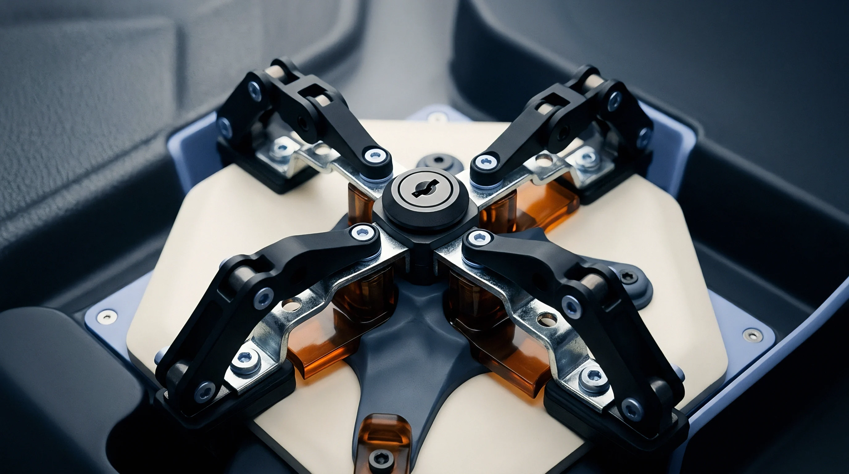

Pressure
Interfacial pressure dictates both contact resistance and ionic tortuosity through the separator. Calibrated stack compression holds active material, conductive carbon, and current collectors in intimate contact, which cuts bulk ohmic losses and prevents delamination as the electrodes breathe. Squeeze the stack too hard, however, and the separator collapses, choking off ion paths and promoting localized lithium plating.
Excessive module clamping force crushes the porous separator while insufficient load permits active particle disconnection.
The published 0.30 MPa optimum for 280-Ah lithium iron phosphate prismatic cells is based on single-cell cycling at 0.5C and 25 degrees Celsius in rigid platens; pushing charge rates past 1.5C or lowering temperatures to 0 degrees Celsius speeds up lithium plating under that load, requiring a lower baseline of 0.15 MPa to keep separator pores open. Above 1.0 MPa, microporous polyethylene yields plastically, driving up tortuosity and cell impedance.
Civil engineers deal with the same dynamic when swelling soil heaves pavement against an unyielding abutment: rigid restraint simply converts volumetric expansion into destructive shear stress.
Optimal Target Windows across Common Chemistries
Commercial prismatic cells must operate within narrow pressure bands to maintain electrical contact without fracturing particles. The chemistry of the cathode largely determines this tolerance: olivine crystals give lithium iron phosphate the structural stability to handle stiff clamping, whereas nickel-manganese-cobalt particles micro-crack if subjected to excessive transverse stress during high-rate discharge.
| Chemistry and Format | Initial Preload Window (MPa) | Maximum End of Life Pressure (MPa) | Reversible Single Cycle Dilation | Irreversible Cyclic Swelling |
|---|---|---|---|---|
| LFP Prismatic (Aluminum Case) | 0.20 to 0.35 | 0.80 to 1.20 | 1.5% to 2.2% | 6.0% to 10.0% |
| NMC 811 Prismatic (Aluminum Case) | 0.15 to 0.30 | 0.70 to 1.00 | 2.0% to 3.5% | 5.0% to 8.5% |
| NMC 622 Pouch (Laminated Film) | 0.05 to 0.15 | 0.40 to 0.60 | 4.0% to 7.0% | 8.0% to 14.0% |
| Silicon-Graphite Blend Pouch | 0.10 to 0.25 | 0.85 to 1.40 | 6.0% to 11.0% | 12.0% to 22.0% |
| Values represent nominal operational bounds derived from multi-cell module compression testing under 0.5C charge and 1C discharge regimes. | ||||

Worked Stress Evolution in Fixed Cavities
A stack of twenty-four 280-Ah prismatic cells shows what happens under unyielding constraint. With a nominal cell thickness of 71.50 millimeters and a tolerance of plus or minus 0.50 millimeters, nominal stack length sits at 1,716.0 millimeters. Assuming rigid steel platens tied by invar side plates lock that cavity dimension to exactly 1,716.0 millimeters, fresh cells installed at 30 percent state of charge take an initial preload of 0.25 MPa.
Charging to 100 percent causes an initial reversible expansion of 1.8 percent. Unconstrained, the stack would lengthen by 30.88 millimeters. Confined to a fixed cavity, that strain converts directly to internal stress via the compressive modulus of the jelly roll.
Dry windings average 120 MPa in compression, but that drops to 45 MPa once wetted with electrolyte. Multiplying the restrained 0.018 strain by the wet modulus of 45 MPa gives a stress jump of 0.81 MPa. Factoring in the 0.25 MPa preload brings total interfacial pressure to 1.06 MPa by the end of the first charge.
Irreversible swelling compounds this baseline over 2,500 cycles. At an end-of-life swell of 7.0 percent, an unconstrained stack would grow by 120.12 millimeters. Inside a rigid frame, casing yield and separator compaction alter the modulus, and as separator pores collapse under overload, internal pressure climbs past 2.80 MPa.
That load crushes separator edges, buckles the aluminum cans against the platens, and shears internal current collector tabs.
Over-compression degrades cells through a defined mechanical sequence:
- Separator compaction closes sub-micron pore structures, elevating ionic resistance across the separator membrane.
- Electrolyte expulsion squeezes liquid phase solvent out of the central jelly roll toward the casing perimeter voids.
- Active material pulverization breaks particle-to-binder interfaces under extreme local shear forces.
- Lithium plating triggers thermal runaway when blocked transport forces lithium ions to accept electrons on the anode surface as dendrites.

Creep Relaxation and Interfacial Delamination
Polymers in the stack relax under sustained mechanical load. Both the separator and internal plastic insulators exhibit viscoelastic creep, causing initial preload to drop by 20 to 40 percent across the first two hundred hours of rest if the design does not compensate for relaxation. That drop loosens the stack, leaving low-pressure zones where electrode layers peel away during subsequent cycling.
Swelling forces exceeding published envelopes are attributed either to abusive customer charging or to internal mechanical defects.


Cushion
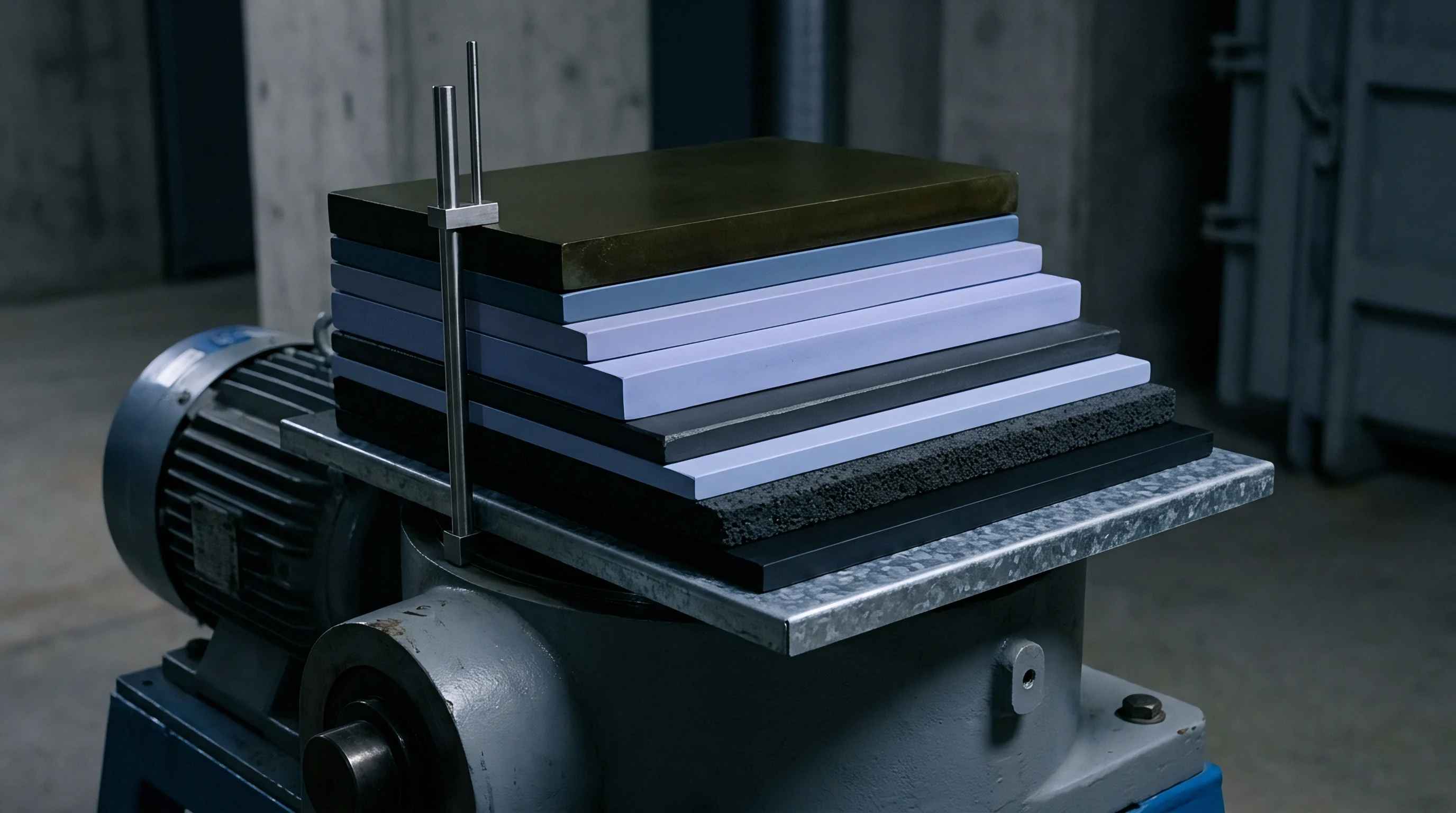
Inter-cell compliance pads absorb volumetric expansion while keeping surface pressure within target limits. Acting like springs in series with the cells, these elastomeric cushions trade displacement for modest pressure rises; without them, a rigid enclosure converts normal breathing into severe stress spikes, while foam thickness directly sets cell pitch.
Because solid elastomers exhibit nonlinear stress curves and are essentially incompressible, solid rubbers bulge laterally under load rather than compressing cleanly. Microcellular polyurethane foams, closed-cell silicone sponges, and aerogel blankets resolve this by providing open or closed void space, collapsing internal cells to maintain stable pressure across substantial compression strokes.
IEC 62660-1 test clauses leave clamping rigidity unspecified, allowing cell vendors to publish cycle figures derived under idealized laboratory presses.

Compression Force Deflection Mechanics
Cellular elastomers progress through three distinct deformation regimes: linear elasticity, a plateau, and densification. In the linear phase, pore struts flex elastically. As load increases, the struts buckle, producing a broad plateau where the pad absorbs substantial stroke with minimal pressure gain.
Once the pores fully collapse, the material hits densification, and the stress-strain curve shoots up vertically.
The nominal 25 percent compression deflection rating of 0.28 MPa for open-cell polyurethane foam relies on ASTM D3574 dry laboratory testing at 23 degrees Celsius; prolonged cycling at 50 degrees Celsius inside an active module induces chemical relaxation that degrades that resistance by 35 percent over 1,000 cycles. Cushion thickness is selected to ensure cell swelling stays strictly within the plateau region, keeping the material clear of densification across the life of the pack.

Material Selection between Foams and Aerogels
Polyurethanes and silicones present distinct trade-offs under thermal aging. Microcellular polyurethane offers excellent initial elasticity at low cost, but suffers from severe compression set after prolonged exposure above 50 degrees Celsius. Silicone sponges tolerate harsher thermal environments, retaining elasticity from minus 40 degrees Celsius to 150 degrees Celsius, though at a significant cost premium.
Aerogel composites serve a dual purpose: they provide mechanical compliance while acting as thermal barriers that halt propagation between cells.
| Material Class | Plateau Modulus (MPa) | Compression Set (50°C, 22h) | Thermal Conductivity (W/m·K) | Densification Limit Strain |
|---|---|---|---|---|
| Microcellular Polyurethane | 0.15 to 0.40 | < 5.0% | 0.07 to 0.11 | 55% to 65% |
| Closed-Cell Silicone Foam | 0.20 to 0.55 | < 2.5% | 0.09 to 0.14 | 50% to 60% |
| Silica Aerogel Blanket | 0.30 to 0.70 | < 8.0% | 0.018 to 0.024 | 40% to 50% |
| Crosslinked Polyolefin Foam | 0.10 to 0.35 | > 12.0% | 0.04 to 0.06 | 45% to 55% |
Specifying elastomeric compression pads requires precise qualification steps:
- Compression force deflection curves characterize the plateau slope across temperatures ranging from minus 20 degrees Celsius to 60 degrees Celsius.
- Compression set resistance measures the unrecovered thickness fraction after sustained 50 percent deflection at maximum operating temperature.
- Cyclic fatigue endurance tracks stress retention across 5,000 continuous displacement cycles at representative pack breathing amplitudes.
- Thermal conductivity degradation verifies that mechanical densification does not compromise required inter-cell insulation ratings.
Adding ISO 12405-4 spring-rate retention clauses to procurement specs requires suppliers to validate compression set under simultaneous thermal and mechanical aging.

Envelope
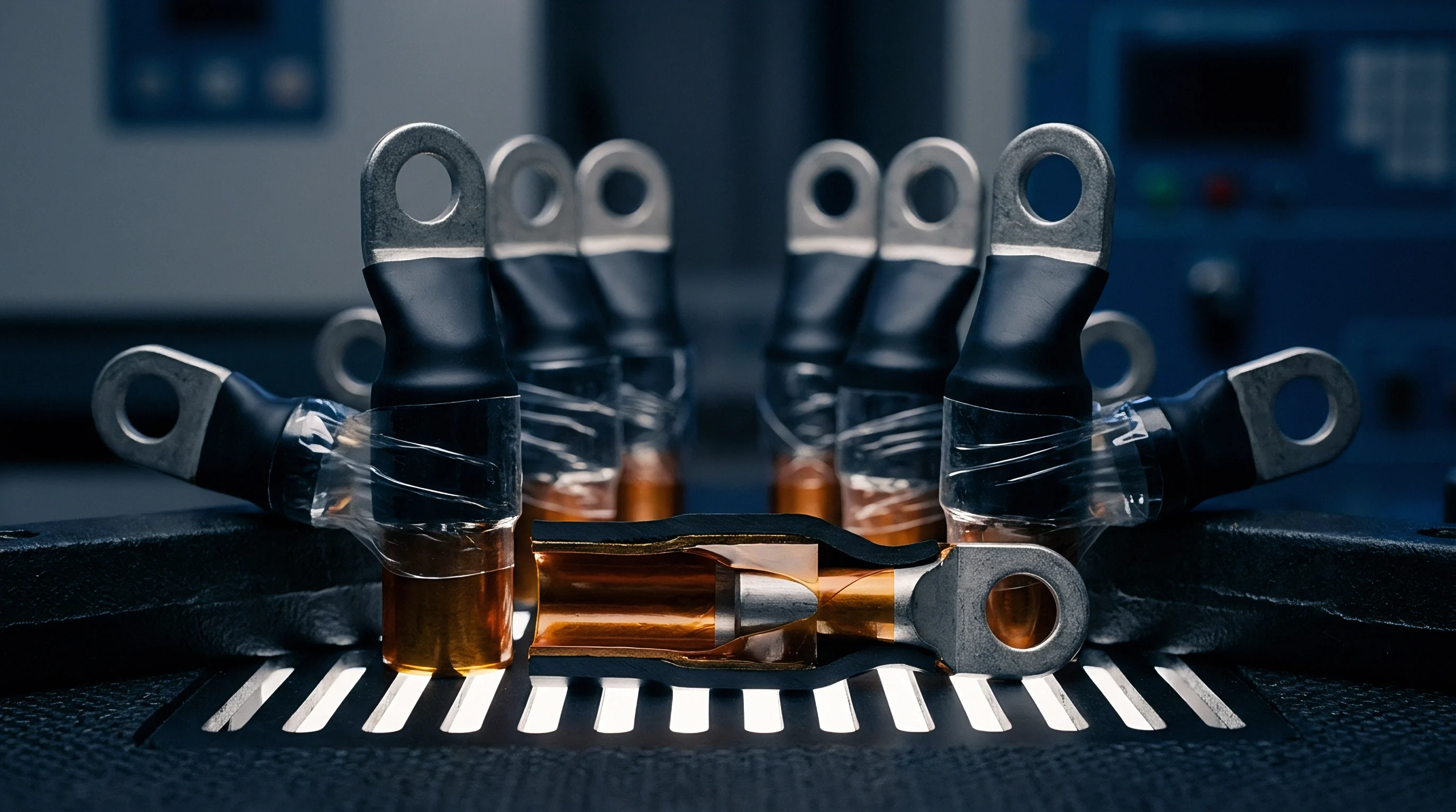
Pack design must allocate volume for both manufacturing variance and ongoing cell expansion. Incoming cells carry individual tolerances in length, width, and thickness that add up across a forty-eight-cell module into substantial dimensional spread. The containment structure has to accommodate those initial manufacturing tolerances alongside years of cyclic and irreversible breathing.
Because structural enclosures cannot push into adjacent vehicle compartments, maintaining fixed external dimensions over warranty life requires balancing cell capacity bins, cushion thickness, and platen stiffness.

Tolerance Stacks in High Cell Counts
Cell thickness tolerances accumulate linearly down an unconstrained module assembly line. On a standard 100-Ah prismatic format with a thickness tolerance of plus or minus 0.40 millimeters, stacking sixty cells yields a worst-case dimensional variance of plus or minus 24.0 millimeters. Fixed-displacement tooling under these conditions leaves short stacks loose while over-compressing tall stacks before any electrical current is applied.
Force-controlled assembly avoids this variability. Servo presses compress the cell stack until load cells register the target preload, regardless of travel distance. The station then measures the resulting stack dimension, inserts matched shims or sets tie-rod pinning points accordingly, and locks the module assembly.

Contract Boundaries on Degradation Metrics
Supply agreements set binding limits on irreversible thickness growth across the warranty term. Cell vendors typically quote cycle performance under rigid zero-deflection platens or constant-force lab fixtures, neither of which reflects the variable stiffness and thermal gradients found in real battery packs.
Designers often assume an 8.0 percent end-of-life swell for high-nickel prismatic cells, yet teardowns reveal actual swelling between 5.2 percent and 11.4 percent depending on charging limits and local temperatures. Faced with that spread, pack integrators design for 12.0 percent expansion while trying to hold cell suppliers contractually to 7.5 percent. Without clear definitions of test boundary stiffness in procurement agreements, integrators carry the warranty risk when modules swell beyond expectations in the field.
Rigid pack boundaries require generous mechanical clearances, whereas flexible spring-loaded packs demand unyielding thermal conduction paths.