Automated Meter Mix Dispensing Dynamics for Thermally Conductive Gap Fillers
Volumetric displacement precision, shear rate thermal control, and wear-resistant fluid metering govern automated thermal gap filler dispensing performance.


Feed
Delivering primary fluid from bulk totes to automated meter-mix units relies on positive-displacement actuation when filler loadings exceed seventy percent by volume. At high viscosities (100,000 mPa·s to 1,500,000 mPa·s), liquid gap fillers encounter steep flow resistance inside inlet manifolds, where piston wear gradually degrades volumetric accuracy. Feeding material from 20-liter pails or 200-liter drums requires hydraulic follower plates applying 0.2 MPa to 0.6 MPa of mechanical down-force to push dense silicone or polyurethane resins into hose lines without causing cavitation at pump suction ports.
Progressive cavity pumps and servo-driven piston metering systems serve distinct roles in continuous automated feed runs. Progressive cavity units produce smooth, pulseless flow along long dispense beads, but heavy ceramic particulate loading wears down rotor-stator seals and increases fluid back-slip above 4.0 MPa. By contrast, dual-piston servo pumps maintain volumetric repeatability within 0.5 percent at supply pressures up to 15.0 MPa.
Because reciprocating pistons create pressure ripples during stroke reversals, line designers use pulse dampeners or synchronized crossover valves to prevent thin spots in the laid bead.
Air entrained inside bulk containers skews volumetric metering because bubbles collapse under discharge pressure, shifting the ratio between Component A and Component B. Vacuum degassing (10 mbar to 50 mbar) before drum loading pulls out these micro-bubbles, while pressurized follower plates keep the resin dense ahead of the primary displacement valves to prevent intake cavitation.
| Pump Architecture | Maximum Discharge Pressure (MPa) | Volumetric Tolerance Range (%) | Particulate Abrasion Resistance | Maintenance Cycle Interval (Cycles) |
|---|---|---|---|---|
| Servo Dual Piston | 15.0 | ±0.5 | Moderate to High | 250,000 |
| Progressive Cavity | 4.0 | ±1.5 | Moderate | 100,000 |
| External Precision Gear | 2.5 | ±3.0 | Low | 25,000 |
| Peristaltic Tube Meter | 0.8 | ±5.0 | High | 50,000 |
Volumetric Displacement under Compressible Void Phases
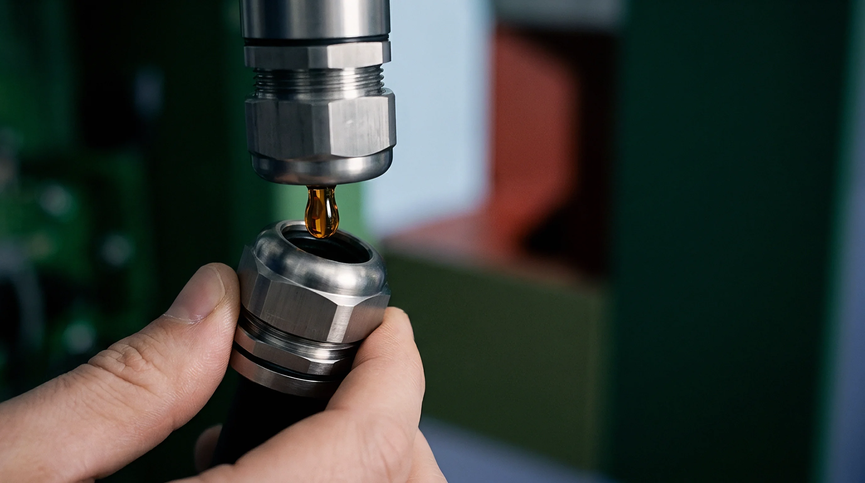
Gas inclusions lower the bulk modulus of the gap filler. When a dual-piston displacement cylinder takes in resin with two percent entrained air by volume, hydraulic pressure must compress that gas phase before the discharge valve opens. The piston spends three to five percent of its stroke simply building opening pressure, creating dead travel that cuts shot volume during high-speed dot dispensing.
Conditioning manifolds keep feed pressure steady as reciprocating bulk pumps transfer resin through smooth-bore, stainless-steel-braided PTFE lines. However, flexible hose expansion under pressure spikes alters system volume and causes lag during robot start-stop cycles. Replacing hoses with rigid stainless steel piping eliminates this compliance, ensuring immediate pressure response at the head control valve.
When volumetric deviation exceeds target thresholds, drift can stem from ambient temperature shifts in the staging bay or pump seal erosion.

Shear
Viscous deformation within conduit channels reshapes the flow profile during high-speed dispensing. Dense thermal gap fillers behave as thixotropic, non-Newtonian fluids modeled by Herschel-Bulkley mechanics. Resin remains rigid until applied shear stress exceeds its static yield stress ~ typically 50 Pa to 300 Pa ~ after which apparent viscosity drops sharply as shear rate increases, allowing heavily loaded alumina slurries to move through narrow lines.
Fluid conduits operating below three inner diameters from nozzle tips maintain lamina stability without inducing phase separation in high-density alumina slurries.
High shear inside narrow nozzle tips generates localized friction within the resin matrix, where viscous dissipation can raise fluid temperature by 5°C to 15°C during fast dispense strokes. This heating lowers matrix viscosity while accelerating cross-linking in two-part polyurethanes or silicones. Left unchecked, nozzle heating shortens pot life and causes premature gelation inside static mixers.
Fluid Network Sizing and Conduit Mechanics
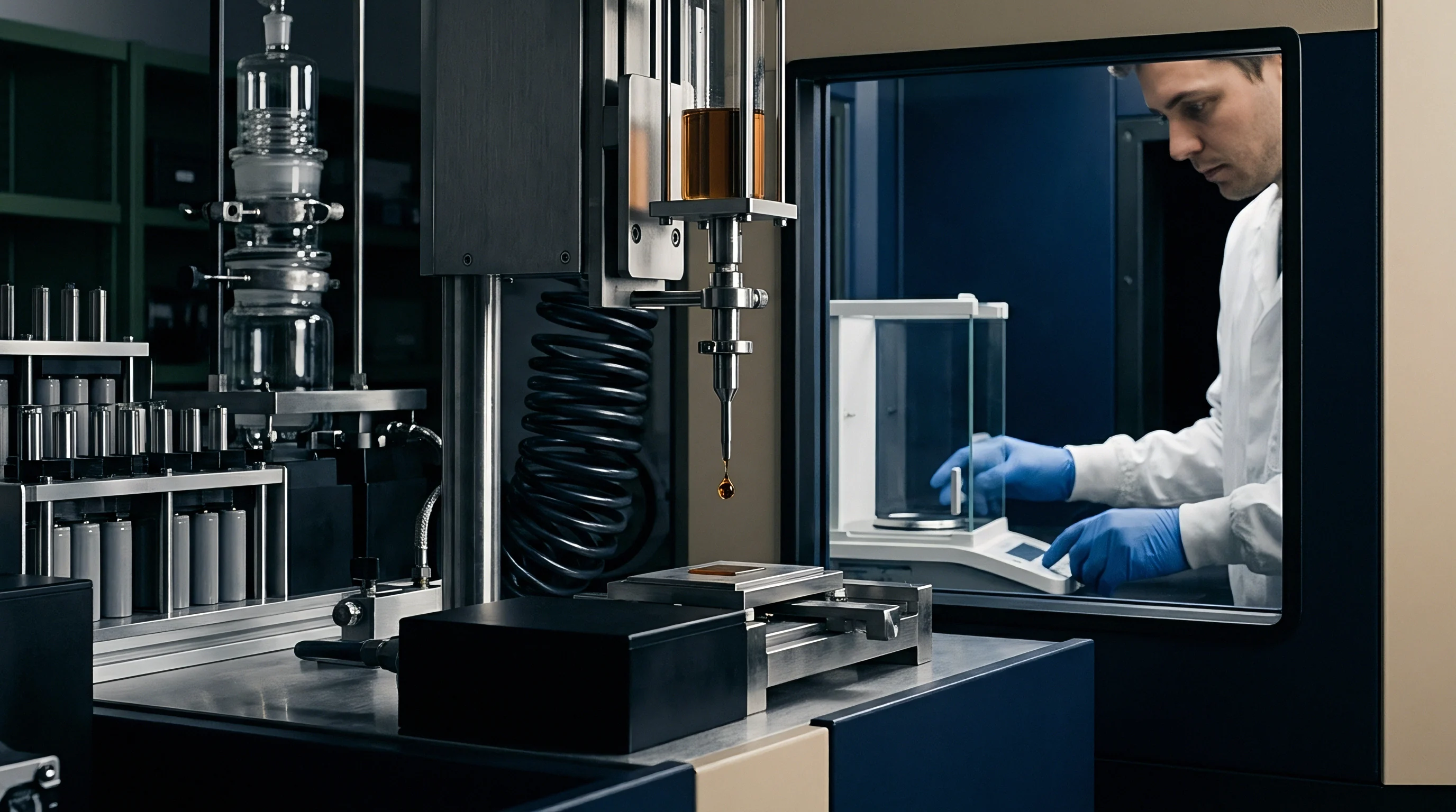
Sizing fluid lines requires balancing hydraulic pressure losses against the cost of purging dead volume during production halts.
- Conduit inner diameter determines both the hydraulic pressure drop and the volume of resin lost during line flushes.
- Bend radius geometry must exceed five pipe diameters to prevent filler particles from migrating across velocity streamlines.
- Thermal jacket profiling holds fluid temperature within one degree Celsius to prevent yield-stress drift.
- Pressure transducer location directly upstream of the mix head gives accurate readings of dynamic flow resistance.
Because flow rates govern shear forces, steep velocity gradients across a conduit can trigger phase separation if local shear rates exceed stability limits. Ceramic particles migrate toward the low-shear center axis, leaving a thin, resin-rich boundary layer against the tube walls. This wall-slip effect shifts velocity profiles away from a parabolic curve toward plug flow, making uniform diameter transitions necessary to prevent particle compaction and plugging.
Maintaining uniform fluid velocity through smooth, conical nozzle transitions prevents phase separation between ceramic filler particles and the polymer matrix.
Mixing
Blending Part A resin with Part B hardener at the dispense head dictates cross-link density and thermal performance. Two-part fillers demand strict stoichiometric control across ratios from 1:1 up to 10:1 by volume. Fluctuations in feed rate leave unreacted resin or excess catalyst in the bead, which lowers mechanical hardness, increases volatile outgassing, and drops thermal conductivity below specification.

When Does Static Mixing Outperform Dynamic Agitation?
Disposable element nozzles eliminate solvent flushes while thoroughly mixing 1:1 two-component resins. These static mixers pass fluid through repeating baffles that split and recombine the streams 16 to 32 times. However, static elements build substantial backpressure tied to fluid viscosity and flow velocity, requiring heavier valve blocks and higher pump drive power to overcome the pressure drop.
Dynamic mix heads use motorized impellers within small chambers to blend wide off-ratio formulations, such as 10:1 mixes, without generating extreme line pressures. High shear inside the chamber requires active cooling jackets to absorb heat, as well as automated solvent flushing or mechanical purging during line pauses to prevent material from curing inside the head.
Moisture ingress accelerates filler settling.
Pressure loss across static mixer geometries follows modified Hagen-Poiseuille relations adjusted for shear-thinning power-law fluids:
Δ P = frac128 · μeff · Q · Lπ · D4
Where μeff represents effective apparent viscosity at local shear rate, Q is total volumetric flow rate, L is mixer length, and D is internal mixer hydraulic diameter. Elevated backpressure increases pump drive torque requirements and stresses valve seals.
ISO 21546 Section 6.2 limits stoichiometric variance between component streams to within two percent of baseline across the full dispense cycle, placing batch rejection risks on the line integrator whenever automated metering strays from target mass ratios.
Wear
Heavy ceramic loading causes rapid mechanical wear across internal wetted surfaces during extended production runs. To achieve thermal conductivities between 1.5 W/m·K and 6.0 W/m·K, gap fillers rely on hard inorganic powders like spherical alumina (Al2O3, Mohs hardness 9), aluminum nitride (AlN, Mohs hardness 8), or boron nitride (BN). Under continuous motion, these sharp particles abrade steel manifolds, valve seats, and metering pistons.
As filler erosion degrades nozzle geometry, abrasive wear also opens up internal machining clearances inside positive displacement pumps. A radial clearance expansion of just 5 micrometers between piston and sleeve permits back-leakage under 10 MPa working pressures, reducing volumetric efficiency by 8 to 15 percent and driving dispensing accuracy outside statistical process control limits.
- Disconnect supply line pressure fittings and relieve residual hydraulic pressure through the manifold bleed valve into a grounded metal receiver.
- Inspect piston sleeve clearances using optical bore gages to measure radial surface recession against engineering thresholds.
- Purge five dead-volumes of unmixed resin through fresh metering valves to flush settled filler particles from internal dead-legs.
- Verify volumetric calibration using gravimetric shot-mass measurements on a calibrated four-decimal balance.
| Component Surface | Substrate Base Material | Surface Coating / Hardening | Volumetric Loss Rate (mm³ per 10k Cycles) | Primary Failure Mode |
|---|---|---|---|---|
| Metering Piston Sleeve | 316 Stainless Steel | None (Raw Machined) | 12.4 | Scoring and Internal Back-Slip |
| Check Valve Ball Seat | Tool Steel D2 | Liquid Nitriding | 3.1 | Seat Pitting and Backflow Loss |
| Dispense Nozzle Tip | Tungsten Carbide | Uncoated Carbide | 0.2 | Orifice Enlargement and Bead Flare |
| Rotary Valve Core | Zirconia Ceramic (ZrO2) | Polished Ceramic Surface | 0.05 | Seal Ring Grooving |
To prevent volumetric drift from component wear, wetted parts require surface hardening against prolonged particle impact. Hardened tungsten carbide, silicon nitride ceramics, and diamond-like carbon (DLC) coatings protect valve seats and piston sleeves from micro-scouring. Uncoated stainless steel fluid paths wear down quickly, producing metal shavings that pollute gap filler batches and risk electrical shorts inside battery modules.
Undetected valve seat erosion allows backflow between high-pressure strokes, altering shot weight and creating thermal voids that can trigger localized cell overheating during fast charging.

Pressure
Hydraulic reaction forces during module placement dictate final bondline thickness between battery cells and cold plates. Squeeze flow kinetics govern material movement as cells press into the freshly laid bead profile. The force required to compress viscous filler rises nonlinearly as the gap narrows, following modified Stefan squeeze flow equations for non-Newtonian fluids.
Uncontrolled compression speeds exceeding two millimeters per second generate hydraulic reaction forces capable of permanent aluminum cold plate deformation.
Excessive force can distort cooling plates and strain cell enclosures. Laying a multi-bead pattern or engineered snake layout lowers resistance compared to a single heavy center bead by shortening fluid travel distance and letting air escape ahead of the advancing wet-out front.
Trapped ambient air pockets impair heat transfer while degrading electrical isolation across the gap filler interface. Air has a thermal conductivity of roughly 0.026 W/m·K, creating localized hot spots when trapped between prismatic cell bases and cold plates. Furthermore, partial discharge breakdown occurs inside micro-voids at voltages well below the dielectric strength of solid resin (10 kV/mm to 15 kV/mm), compromising high-voltage pack safety.
- Incomplete wet-out front propagation leaves air pockets trapped along rough cooling plate surfaces.
- Rapid bead joining traps air channels between parallel dispenses when fluid velocity outpaces air displacement.
- Outgassing volatiles expand during exothermic curing, forming micro-void networks within thick bondlines.
- Non-uniform compression force causes asymmetric gap closure, pushing fluid away from outer cell contact edges.
Mechanical press parameters require close alignment with fluid yield stress and viscosity to avoid warping aluminum cold plates. Servo-electric presses using multi-stage velocity profiles prevent structural pack deformation while forcing gap filler into surface micro-roughness grooves.
Whether inline acoustic emission monitoring can reliably distinguish between micro-void coalescence and structural filler crushing during high-speed pack compression remains unverified across volume production lines.

Ledger
Accounting for automated dispensing infrastructure balances capital expenditure against scrap losses and downtime. Thermal gap fillers represent a major recurring cost in EV pack production, running from $15/kg to $60/kg depending on ceramic loading and thermal rating. Purge losses during shift changes, static mixer swaps, and drum turnover directly inflate unit manufacturing costs.
Evaluating disposable static mixers against dynamic, solvent-flushed mix systems involves weighing resin loss against capital payback schedules. Disposable static mixers consume material at every swap and generate solid chemical waste. Dynamic systems recover resin using solvent flushes, but introduce solvent disposal costs and VOC compliance overhead.
A five percent material purge reduction saves more capital over three production years than the total initial investment in high-precision metering heads.
A plant producing 50,000 battery packs annually consumes roughly 60,000 kg of 3.5 W/m·K gap filler ($45/kg). Using disposable static mixers changed at every shift pause (three shifts per day) generates 1.8 kg of wasted resin per line daily. Across 300 operating days, material loss reaches 540 kg ~ equal to $24,300 in direct waste per dispensing station.
Dynamic heads cut resin purge mass by 80 percent, saving $19,440 per line annually against an initial capital cost of $35,000 per head assembly.
| Cost & Performance Metric | Disposable Static Nozzle Architecture | Dynamic Solvent-Flushed System | Financial Breakeven Threshold |
|---|---|---|---|
| Initial Capital Expense (NRE) | $12,000 per metering station | $48,000 per metering station | 36 Months Payback Window |
| Consumables Cost per Shift | $10.50 (3 Nozzles @ $3.50) | $2.40 (Solvent + Waste Processing) | >2 Shifts per Day Production Rate |
| Purge Material Loss per Pause | 120 grams to 350 grams | 20 grams to 45 grams | Material Price >$30/kg |
| Line Downtime for Changeover | 2 Minutes (Manual Swapping) | 30 Seconds (Automated Flush Cycle) | Takt Time <120 Seconds per Module |
Because dispensing dynamics dictate final pack quality, line yield, and unit cost structures, hardware selection must align with fluid mechanics and operational constraints. Specifying components without matching flow dynamics, particle tribology, and mechanical reaction forces leads to line stoppages and warranty exposure at the module interface seam.