Module Housing Tolerances Where Thermal Paste Budgets Die
Tightening housing floor machining planarity below 0.2 mm slashes thermal paste volume requirements, preventing multi-million dollar annual BOM overruns.

Gap
Dimensional accumulation in battery module assemblies defines the baseline boundary condition for heat transfer. When a pack designer specifies a nominal thermal interface bond line of 0.5 mm, that figure reflects idealized CAD geometry where every part sits at its exact midpoint. On the line, planar deviation, extruded tray wall camber, stamped sheet metal floor crown, and pouch swelling all push the interface away from nominal.
An extruded 6063-T6 aluminum floor carries a local flatness tolerance of 0.3 mm per 100 mm of span under standard commercial specifications. Across a 600 mm tray, baseline structural unflatness reaches 1.8 mm before accounting for weld shrinkage or cell stack variations. The resulting clearance between cell casings and the cooling plate expands and contracts across the module footprint.
Uncontrolled clearance between cell bases and liquid-cooled heat sinks directly degrades thermal dissipation. Liquid gap fillers loaded with alumina or aluminum nitride powders deliver bulk thermal conductivities between 1.5 W/m-K and 4.0 W/m-K. Structural aluminum alloys conduct heat at roughly 160 W/m-K, while active lithium-ion cells generate internal heat fluxes up to 15 kW/m³ during 3C fast charging. When housing variations let actual interface thickness balloon from 0.5 mm to 2.2 mm, local thermal resistance spikes by 340 percent.
Heat trapped in central cells accelerates SEI breakdown and causes uneven capacity loss across the module string.
Mechanical Stack Vectors in Prismatic Arrays
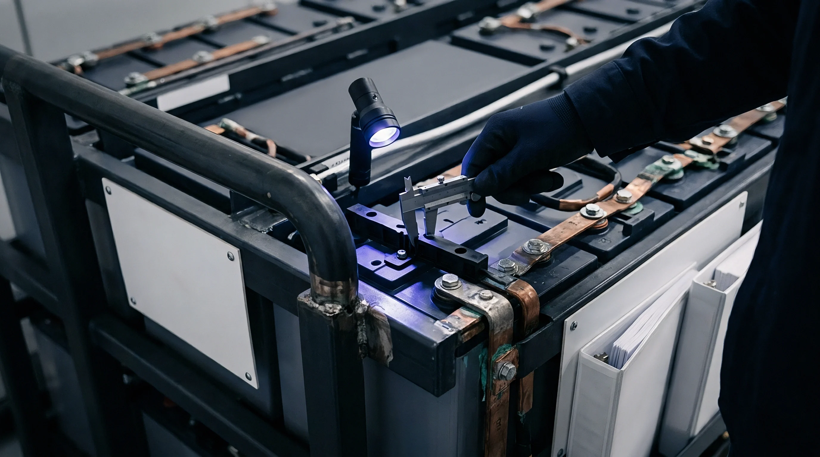
Linear manufacturing tolerances accumulate quickly along an assembly rail. A standard 120 Ah prismatic cell in an aluminum can carries an enclosure thickness tolerance of +/- 0.3 mm. Stacking twelve such cells in a single side-frame module creates a combined tolerance band of +/- 3.6 mm.
Adding side compression foam to absorb anode expansion over life introduces another +/- 0.5 mm of pad tolerance. Side rails bolted or laser-welded to rigid end plates constrain cavity length, forcing longitudinal variations to express as transverse compression or downward Z-axis bow.
When the cell stack reaches maximum material condition, the bottom of the array loses planar contact with the baseplate. Under peak compression, individual cells tilt or lift from the tray floor, leaving wedge-shaped pockets. Torquing end-plate tie rods to nominal specification can induce up to 1.6 mm of vertical displacement at the center of a fourteen-cell prismatic array.
This cavity forces the thermal interface paste to bridge starkly different gap heights beneath adjacent cells in the same string.
A 1.5 millimeter increase in bond line thickness raises cell-to-case thermal resistance by 240 percent when utilizing a 2.0 W/m-K thermal gap filler under 100 kPa clamping pressure.
Extrusion die wear introduces steady dimensional drift over time. Aluminum dies distort over production runs of five thousand units, widening wall channels and altering baseplate concavity. Machining mounting surfaces after extrusion restores planarity, but adds cycle time and capital tooling costs.
Unmachined extrusions force thermal gap filler to act as a structural shim rather than a thin conductive layer.
Housing Surface Deflections across Extruded Bottom Trays
Welding side walls to bottom cooling plates introduces intense localized heat into the aluminum structure. Friction stir welding and laser seam welding both generate differential thermal contraction during cooling. A plate detailed flat to within 0.2 mm distorts post-welding into a wavy profile with peak-to-valley amplitudes exceeding 1.2 mm.
Grain growth and localized stress relief in the heat-affected zone permanently shift the resting shape of the tray floor.
Tolerance stack-ups frequently exhaust design margins well before final assembly.
Structural housing flex alters the heat conduction path across the floor.
Sheet metal enclosures formed on press brakes present distinct tolerance challenges compared to aluminum extrusions. Stamping spring-back varies with coil hardness, sheet gauge variance, and grain orientation relative to the bend line. Cold-rolled steel trays are prone to oil-canning, where the floor oil-cans between concave and convex profiles under load.
A floor that snaps downward under module assembly pressure doubles the gap directly beneath the hottest central cells.
Mechanical interface variations trigger specific structural and thermal failure modes within the module assembly:
- Cohesive Paste Splitting occurs when dynamic housing deflection exceeds the structural elongation limit of cured gap filler, opening air gaps along the heat flow path.
- Localized Cell Hotspots develop beneath cell bases where over-thick thermal paste impedes heat dissipation, driving local temperature deltas beyond 8 degrees Celsius between adjacent cells.
- Bottom Plate Bulging manifests when high-viscosity gap filler is compressed into tight gaps, generating hydrostatic back-pressure that permanently deforms thin-gauge enclosure floors.
- Solder Joint Fracture strikes cell monitoring harnesses when individual cells tilt relative to the housing floor during module insertion.
Quantifying dimensional variance requires structural tolerance mapping across every component in the stack. Mechanical designers combine statistical worst-case and root-sum-square models to predict maximum gap heights. Root-sum-square calculations assume a normal distribution of part tolerances centered on nominal dimensions, an assumption frequently upended on the shop floor by tool wear, raw material batch shifts, and weld distortion bias.
| Process Method | Component Standard Tolerance | Planar Bow per 500 mm | Thermal Gap Range | Paste Budget Multiplier |
|---|---|---|---|---|
| Unmachined Aluminum Extrusion | +/- 0.40 mm | 1.20 mm | 0.3 mm to 2.1 mm | 2.4x |
| CNC Fly-Cut Aluminum Extrusion | +/- 0.08 mm | 0.15 mm | 0.4 mm to 0.8 mm | 1.1x |
| Stamped Steel Sheet Enclosure | +/- 0.50 mm | 1.80 mm | 0.2 mm to 2.8 mm | 3.1x |
| Die-Cast Aluminum Cold Plate | +/- 0.25 mm | 0.60 mm | 0.3 mm to 1.5 mm | 1.7x |
| Data reflects measured first-article inspection samples across 120 pack module production batches evaluated under ambient laboratory conditions. | ||||
Measured geometric stack-ups across trial builds show tolerance distributions skewing heavily toward maximum material condition. Under these conditions, the volume of thermal gap filler required for full surface wet-out exceeds nominal engineering calculations by 82 percent. Injecting additional paste manually to eliminate voiding identified during thermal imaging validation adds an unbudgeted material penalty of $14.60 per module during low-rate initial builds.
Viscosity
The fluid properties of liquid thermal interface materials dictate how gap fillers behave during automated dispensing and structural compression. Two-part polyurethanes and silicones carry heavy loadings of ceramic powders such as alumina, aluminum hydroxide, and boron nitride. Ceramic loadings often exceed 85 percent by weight to reach conductivities above 2.0 W/m-K. This dense particle loading turns the material into a non-Newtonian, thixotropic suspension with high yield stress and strong shear-thinning resistance during displacement.
Dispensing high-viscosity pastes into variable gaps creates clear fluid dynamics hurdles. When a volumetric dispenser applies paste to a tray, the bead profile depends on tip velocity, pump pressure, and material temperature. When the cell array lowers into position, the paste must spread laterally to wet the entire base of every cell.
A narrow gap caused by a low-tolerance tray increases the compressive force needed to drive paste outward.

Rheological Behavior under Automated Dispense Shear
Pumping highly filled thermal materials generates intense shear forces inside dispensing nozzles and metering valves. Shear rates inside high-speed automated nozzle tips top 10,000 inverse seconds. Under this shear, apparent viscosity drops, allowing material to flow through narrow feed lines.
Once the paste exits the nozzle and lands on the module floor, shear drops to zero and the material rapidly recovers its resting yield stress.
Yield stress prevents the dispensed bead from slumping or running before cell insertion. If yield stress is too low, the bead spreads prematurely, trapping air pockets as the cell base makes contact. If yield stress is too high, the paste resists wet-out, demanding high insertion force to compress the bead.
Excessive compression force flexes thin aluminum trays downward or crushes cell corner radii.
Compression resistance rises non-linearly as clearance narrows.
Trapped air pockets form effective thermal barriers along the floor.
Highly filled gap fillers resist rapid mechanical displacement during insertion.
Dispense temperature largely governs fluid behavior on the line. A 5 degree Celsius drop in ambient temperature raises the initial viscosity of polyurethane gap fillers by up to 40 percent. Higher viscosity impairs metering precision, causing pump cavitation, inconsistent bead volume, and poor coverage.
Heated metering systems maintain paste temperature within +/- 1 degree Celsius, ensuring stable flow rates and consistent bead geometry across shifts.
Displacement Physics and Cell Crushing Thresholds
The force required to compress a fluid bead between two parallel plates scales inversely with the cube of the gap height, matching Stefan squeeze-flow dynamics. As clearance between the cell base and tray floor approaches zero in local high spots, squeezing resistance climbs sharply. An insertion rig applying a steady 5 kN can fail to seat the cell stack fully if local gaps narrow below 0.3 mm across a broad contact area.
Over-pressurization during cell insertion damages internal module components. Excess pressure against thin aluminum cell casings causes internal separator pinch points or electrode margin deformation. Plastic cylindrical cell holders crack under hydrostatic back-pressure from trapped paste.
Automated assembly lines rely on real-time force-displacement monitoring on every insertion press cycle to prevent structural damage.
The physical sequence during high-speed cell insertion moves through distinct force regimes:
- Initial contact occurs between the lower cell surface and the apex of the dispensed gap filler bead, initiating shear flow at minimal resistance force.
- Material displacement begins as the compression tool drives the cell downward at a controlled velocity of 5 mm/s, forcing paste laterally into empty housing voids.
- Shear rate increases dramatically in regions where housing tolerances create localized tight gaps, causing a rapid climb in measured insertion force.
- Wet-out reaches cell perimeter margins, transitioning fluid motion from open-bead spreading to constrained channel squeeze flow.
- Mechanical insertion stops at the targeted mechanical stop position, where peak hydraulic back-pressure exerts maximum static stress on the bottom housing tray.
- Stress relaxation occurs over a 15-second hold window as the polymer matrix relaxes, allowing internal fluid pressure to decay before clamping tools release.
Entrapped air bubbles remain a primary cause of thermal failure in high-viscosity paste dispensing. Air conducts heat at roughly 0.026 W/m-K, creating a thermal barrier. When viscous paste flows around fastener bosses or stiffening ribs, merging fluid fronts trap ambient air pockets.
Higher dispensing speeds aggravate this by driving material faster than its natural wetting velocity across metal surfaces.
IEC 62660-3 vibration compliance testing fails when unreinforced thermal gap paste suffers cohesive shear rupture across unconstrained prismatic cell stack boundaries.
Mixing ratio drift in two-part formulations alters polymer cross-linking density and final Shore hardness. Automated dispense systems blend base resin and catalyst through static mixing tubes right before deposition. Blockages or flow drift in metering pumps alter the stoichiometric ratio, leaving unreacted monomer that never cures.
Uncured paste stays liquid, migrating out of the interface under vehicle vibration and compromising high-voltage insulation boundaries.
Variable housing geometry forces paste along the path of least resistance during high-volume ramps, squeezing material past side retaining walls and away from target heat-transfer zones.

Warp
Operating conditions subject module enclosures to continuous thermomechanical stress. Modules experience cyclic heating under heavy discharge, followed by cooling during low-draw periods or ambient resting. Differential thermal expansion occurs because aluminum housings, steel fasteners, ceramic gap fillers, and cells carry different coefficients of thermal expansion (CTE).
Aluminum expands at roughly 23 ppm/K, while the layered internal cell structure expands at distinct rates along transverse and longitudinal axes.
Cell breathing compounds raw dimensional variation in the housing. Lithium-ion anodes expand and contract during intercalation. Over a five-thousand-cycle operational life, NCM prismatic cells can see permanent volumetric growth of 8 to 12 percent from solid electrolyte interphase (SEI) growth and electrode degradation.
This expansion pushes outward against side walls, causing the tray floor to bow dynamically.

Dynamic Thermomechanical Breathing during Heavy Discharge
Transient thermal gradients induce local thermal stresses that distort structural housing trays. During 150 kW peak acceleration or fast charging, cell temperatures climb rapidly while the bottom cooling plate stays cool under chilled glycol flow. The resulting temperature difference between the top of the tray and the bottom surface creates a thermal bending moment.
The bottom plate crowns upward, compressing paste at the center of the module while placing perimeter bond lines under tension.
Flexural fatigue degrades cured gap filler over extended cycling. Cured polyurethanes offer limited fatigue endurance under cyclic strain. When floor deflections repeatedly strain the material beyond its elastic limit, micro-cracks form within the resin matrix.
These cracks propagate into delamination gaps, breaking the continuous thermal path between the cell base and the cold plate.
Volumetric paste expenses scale poorly when tolerances remain wide.
Scrap and rework costs mount rapidly when thermal bond lines fail inspection.
Cooling plates warp predictably under the localized heat of welding.
Delamination creates localized thermal isolation zones. Once an air gap opens between the cured filler and the aluminum floor, local thermal resistance jumps by orders of magnitude. Affected cells lose their primary cooling path, driving up operating temperatures during high-power events.
The resulting heat accelerates chemical aging, creates capacity imbalances across parallel cell groups, and triggers premature BMS degradation warnings.
What Happens When Cold Plates Flex during Fast Charging?
Chilled coolant running through internal channels under pressure causes elastic deflection in thin cold plate covers. Automotive cooling loops operate at gauge pressures between 1.5 bar and 2.5 bar. Pressure pulses during pump speed transitions push thin plate covers outward toward cell bases.
If the gap filler has cured into a rigid solid, this movement can shear the adhesive bond line directly off the metal surface.
Extensive thermo-mechanical strain tests illustrate how different thermal gap filler chemistries respond to dynamic housing flexing:
| Chemistry Type | Tensile Modulus (MPa) | Elongation at Break | Thermal Conductivity | Fatigue Life (1 mm Cycle) |
|---|---|---|---|---|
| Standard Structural Polyurethane | 450 | 15 % | 1.8 W/m-K | 1,200 cycles |
| Highly Soft Polyurethane Gap Filler | 12 | 120 % | 2.5 W/m-K | 45,000 cycles |
| Silicone-Based Thermal Gel | 0.8 | 250 % | 3.2 W/m-K | 150,000+ cycles |
| Acrylic Thermal Interface Adhesive | 850 | 8 % | 1.5 W/m-K | 450 cycles |
Silicone gap fillers eliminate matrix fatigue thanks to high elasticity and low modulus, but they introduce contamination risks in automotive manufacturing. Volatile siloxanes outgas from silicone matrices over time, migrating toward relay contacts and high-voltage busbar connectors. Under electrical arcing, deposited siloxanes convert into non-conductive silicon dioxide, causing contact resistance spikes and switch failures.
Polyurethane formulations avoid outgassing, but require tighter tolerance management to prevent fatigue shear.
Machining housing mating plates to tighter planarity limits always costs less than filling dimensional variances with excessive high-performance thermal interface materials.
Tie rods and side-rail fasteners gradually lose tension over thermal cycles. Creep in plastic cell holders and settlement of foam compression pads reduce overall stack clamping load. As clamping decays, structural flexure modes shift, moving peak strain points across the bottom thermal interface.
Whether structural housing reinforcements can suppress thermomechanical bending without exceeding pack mass allocations remains an open design challenge.


Budget
Machining tolerances on the housing directly dictate the financial spend on thermal interface materials. High-performance gap fillers loaded with spherical alumina powders cost between $25 and $60 per liter in bulk drums, whereas raw structural aluminum extrusions run roughly $3.50 to $5.00 per kilogram. Relaxing machining tolerances to trim tooling expense simply shifts the cost burden to the bill of materials through increased paste volume.
Volumetric paste consumption tracks maximum gap stack-up rather than the nominal design target. If a module tray specifies a nominal 0.8 mm gap over a 0.25 m² cooling footprint, nominal paste volume equals 0.20 liters per module. Factoring in a worst-case housing flatness tolerance of +/- 0.8 mm means local gaps open to 1.6 mm across wide sections of the floor.
Automated systems must dispense enough material to ensure 100 percent surface contact at maximum gap, pushing actual volume to 0.40 liters per module.

Financial Sensitivity Models for Bond Line Variance
Dispensing excess paste to bridge loose manufacturing tolerances creates severe financial penalties at volume. An automotive assembly facility producing 100,000 battery packs annually, with 8 modules per pack, requires 1.6 liters of gap filler per pack under nominal calculations ~ an annual spend of $6,400,000 at $40 per liter. Adjusting for real-world tolerance stack-ups increases the required volume to 2.8 liters per pack, driving actual annual paste expenditures to $11,200,000.
The resulting $4,800,000 annual variance far exceeds the capital expenditure needed for precision machining. A high-speed CNC fly-cutting station capable of holding baseplate flatness within 0.1 mm across large extrusions costs approximately $650,000 in upfront tooling. Amortizing that equipment over a three-year production run represents roughly $216,666 per year.
Precision milling keeps bond lines thin, yielding a net operational saving of more than $4.5 million annually on paste alone.
Every mechanical interface contributes directly to cumulative tolerance stack.
High filler density turns excess dispensate volume into added mass and cost.
Tooling and die adjustments require immediate capital commitment.
Balancing tooling investment against material consumption requires a structured decision model:
- Raw Extrusion Profiling minimizes initial tooling investment but requires maximum thermal paste budget allocation to fill broad tolerance bands.
- Post-Weld Surface Milling imposes moderate CNC equipment costs while reducing average thermal interface bond line thickness down to 0.4 mm.
- Precision Die-Cast Cold Plates demand high initial tooling NRE investment while holding precise dimensional features that minimize dispensate waste.
- Selective Shim Sorting adds manual assembly labor costs on the factory floor to hand-match cell module stack heights with measured housing tray depths.
Material density adds both technical and cost penalties. Highly filled thermal interface materials carry specific gravities between 2.8 g/cm³ and 3.4 g/cm³. Raising paste volume from 1.6 liters to 2.8 liters per pack adds roughly 3.66 kg of dead weight to the vehicle.
In an electric vehicle, every extra kilogram trims driving range, demanding higher cell capacity that feeds back into overall pack cost.

Machining Tolerances against Volumetric Material Consumption
Manufacturing engineers must weigh the landed cost of the housing assembly against interface material consumption over the entire production life cycle. Tightening stamping tolerances on sheet metal trays requires multi-stage progressive dies fitted with in-die optical sensors and active hydraulic leveling. Precision progressive tooling runs upwards of $800,000 per die set, compared to $250,000 for standard single-stage blanking dies.
| Housing Production Strategy | Upfront Tooling / CNC NRE | Max Local Gap Height | TIM Vol / Pack (L) | Annual TIM Spend (100k Units) |
|---|---|---|---|---|
| Standard As-Extruded & Welded Tray | $150,000 | 2.20 mm | 3.45 L | $13,800,000 |
| Fly-Cut Machined Cooling Face | $750,000 | 0.60 mm | 1.25 L | $5,000,000 |
| Precision Die-Cast Bottom Deck | $1,400,000 | 0.85 mm | 1.60 L | $6,400,000 |
| Active Hydraulic Shim Compensated | $2,100,000 | 0.40 mm | 0.95 L | $3,800,000 |
| Calculations assume $40/L bulk gap filler cost, 8 modules per pack, and 3.0 W/m-K thermal performance grade material across all cases. | ||||
Inline scales integrated into robotic dispense cells flag consumption variances in real time. When housing geometry drifts toward maximum material limits, dispensing robots increase pump output to ensure complete wet-out. If automated dispensing algorithms consume more than 115 percent of target paste weight across ten consecutive modules, line control halts production to flag casting drift.
Automated dispense nozzles cannot compensate for dynamic sheet metal flexure occurring under active clamping pressure during lid securing operations.
Scrap rates from loose-tolerance housings compound the financial hit. When thermal imaging flags voids or thin dry zones on assembled modules, rework requires full teardown. Stripping cured structural paste from cell bases and aluminum housings involves chemical solvent baths and manual scraping, driving up labor hours and risking casing damage.
Standard master supply agreements specify that housing dimensional deviations exceeding drawing profile tolerances within section 4.2 of the quality specification permit the buyer to charge back all excess thermal interface material volume costs directly to the casting foundry.

Receipt
Verifying dimensional compliance on incoming housing parts and cured interface layers requires rigorous metrology. Coordinate measuring machines (CMM) and non-contact 3D optical laser profilers inspect raw trays at receiving gates. A laser profiler sweeps a sheet beam across the tray floor, collecting millions of point-cloud coordinates to construct a digital elevation map.
The scan flags crown distortion, localized weld sink, and mounting hole positional drift within seconds.
Optical mapping at receiving keeps non-conforming housings off the automated dispense line. If an incoming extruded tray displays a local depression deeper than 1.2 mm relative to datum pads, the scanner routes the part for rejection. Catching dimensional defects early prevents dispensing costly thermal interface paste into housings headed for scrap.

Inline Metrology and Optical Profiling Controls
Inline quality systems must also verify thermal paste wet-out after module insertion. Once the cell array seats into the tray of wet paste, non-destructive testing checks the bonded interface. Ultrasonic acoustic microscopy passes high-frequency ultrasound through the aluminum floor into the paste layer.
Echo signals reflected from internal boundaries expose air pockets, delamination, and density variations without damaging the assembly.
Laser profiling confirms surface planarity before parts enter the dispensing cell.
Bond line thickness directly determines interface thermal resistance.
Infrared thermography provides fast thermal validation during end-of-line testing. Pulsing a 300 A thermal excitation current through the cell string while flowing coolant through the cold plate produces clear transient thermal signatures. Cooler spots on the plate surface highlight air voids or incomplete wet-out directly above that zone, identifying thermal bridge defects immediately.

Warranty Responsibility Seams across Interface Boundaries
Clear responsibility boundaries must divide cell manufacturers, casting foundries, material formulators, and pack integrators. When a module experiences thermal runaway from a localized hotspot, assigning root-cause liability relies on assembly inspection records. If inline ultrasound scans confirm that paste wet-out met specified coverage limits, liability moves away from the dispensing operation toward internal cell short-circuit defects.
Comprehensive build logs protect sourcing teams during warranty reviews. Every assembled module receives a laser-etched matrix barcode linking its serial number to its NPI build dossier. That dossier aggregates 3D surface scans of the raw housing, cell stack height measurements, automated paste dispense mass records, and end-of-line ultrasonic wet-out images.
A housing bottom floor showing consistent planarity within half a millimeter protects both the thermal paste bill of materials budget and the long-term field reliability of the pack.