Non Linear Creep Fatigue Microstructural Degradation Modeling in Vacuum Brazed Aluminum Conformal Coolant Nodes
Vacuum brazed aluminum conformal coolant nodes demand nonlinear creep fatigue damage models incorporating grain boundary cavitation and dispersoid coarsening.


Braze
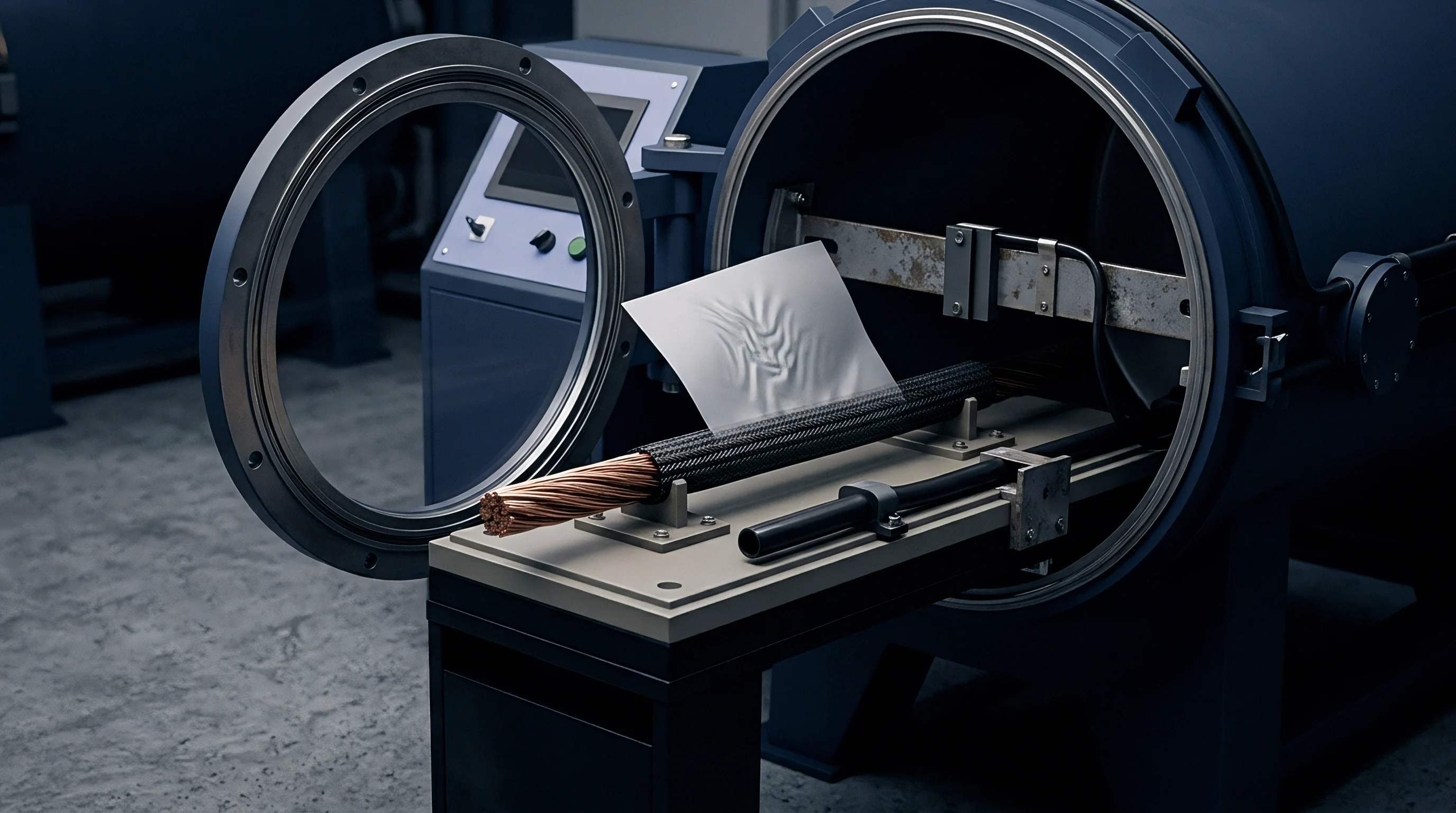
In vacuum brazed aluminum conformal coolant nodes, joint integrity depends on the metallurgical transition between core sheet and braze cladding. Coolant plates for battery pack thermal management typically feature an AA3003 core clad on both faces with an AA4004 or AA4343 aluminum-silicon alloy. Brazing takes place in a hard vacuum furnace at operating pressures between 10 to the power of negative 4 and 10 to the power of negative 5 mbar.
The thermal cycle ramps the assembly to peak temperatures between 590°C and 600°C, melting the silicon-rich cladding layer so it flows into the capillary gap between stamped fluid channels and the cover plate. The core material remains solid, as its solidus temperature sits at approximately 643°C. This flow forms a continuous metallic bridge that serves both as a structural joint and a fluid seal against ethylene glycol water mixtures.
During cooling, silicon particles precipitate within the alpha-aluminum matrix inside the joint fillet. The distribution of these eutectic silicon particles establishes the baseline mechanical behavior of the brazed node. Rapid cooling yields fine, dispersed silicon particles that resist dislocation motion, whereas slow furnace cooling coarse-grains the microstructure.
Analysis shows that the thermal cycle also promotes magnesium evaporation from the cladding alloy, shifting the local solidus boundary and creating micro-segregation zones along the braze interface. Residual stresses then develop during cooling from differential contraction between the core material, the silicon-rich braze alloy, and adjacent structural stiffeners.
In teardowns of returned cooling manifolds, initial defect distributions heavily influence long-term structural survivability. Fillet geometries contain microscopic void networks created by localized outgassing of volatile contaminants or incomplete capillary filling. These voids concentrate stress during pressure cycles and thermal transients.
The local radius of the braze fillet dictates geometric stress concentration factors, which often range from 1.4 to 2.2 under internal hydrostatic pressure. Characterizing the initial mechanical state requires precise mapping of these fillet geometries, void fractions, and localized residual stress fields prior to thermal fatigue exposure.
Thermal Trajectories and Cladding Interface Metallurgy
The thermal trajectory experienced by the cooling node during furnace processing determines how deeply silicon dissolves into the core alloy. Holding peak furnace temperature beyond the optimal dwell window drives silicon deep into the AA3003 core. This diffusion creates a silicon depletion zone within the braze joint and alters local grain structure, shifting the core from an elongated, cold-worked state into a fully recrystallized grain structure that lowers local yield strength near the joint boundary.
Interface boundaries experience localized intermetallic phase formation. Iron and manganese impurities in the AA3003 core combine with aluminum and silicon to form intermetallics like alpha-AlFeMnSi and beta-AlFeSi along grain boundaries within the braze diffusion zone. The shape and size of these phases dictate their susceptibility to microcracking under load: hard, angular beta-phase needles act as stress risers, whereas spherical alpha-phase dispersoids provide mild dispersion strengthening without severely compromising local fracture toughness.
| Alloy Designation | Silicon Content Percentage | Solidus Temperature °C | Liquidus Temperature °C | Max Allowable Void Area Percentage |
|---|---|---|---|---|
| AA4004 | 9.0 to 10.5 | 559 | 591 | 2.5 |
| AA4343 | 6.8 to 8.2 | 577 | 613 | 3.0 |
| AA4045 | 9.0 to 11.0 | 577 | 591 | 2.0 |
| AA4047 | 11.0 to 13.0 | 577 | 582 | 1.5 |
Residual Stress Generation in Conformal Geometry
Conformal coolant nodes possess complex internal flow paths, including branching channels, internal turbulators, and variable-width manifolds. Thermal mass varies significantly across these features. During the cooling phase of vacuum brazing, thinner fluid channel walls cool faster than thick manifold blocks.
This temperature differential generates transient thermal stresses that exceed the dynamic yield strength of aluminum at elevated temperatures, accumulating permanent plastic strain in internal channel corners before the cooling plate reaches room temperature.
The resulting residual stress field remains embedded within the structure, with tensile residual stresses concentrated along the interior roots of the braze fillets. When operational loads apply internal fluid pressure, operational tensile stresses superimpose directly onto these residual stresses. The combined stress state approaches the yield point of the heat-affected aluminum matrix, initiating early micro-plastic deformation during initial coolant pump pressure pulses.
Coolant channel pressure spikes drive local deformation, while interface voids reduce effective load area. Yield stress drops at elevated temperature, though structural compliance helps mitigate peak loads.
Thicker cladding layers lower the melt temperature margin during vacuum brazing, causing localized grain erosion along the fluid fillet boundary.
Interfacial void clusters stem from incoming sheet oil residues that standard pre-wash stages failed to clean.

Microstructure
Operating battery packs subject conformal coolant nodes to temperatures between 45°C and 85°C during high-rate discharge cycles, with localized hot spots reaching 110°C during aggressive fast-charging. Sustained exposure to these elevated temperatures under mechanical load induces continuous microstructural degradation in the aluminum braze joint. Degradation occurs through several distinct physical mechanisms: dispersoid coarsening, solute depletion in the aluminum matrix, silicon particle spheroidization, and grain boundary cavitation ~ each altering the local constitutive mechanical properties of the joint over time.
Dispersoid coarsening transforms fine Al12(Fe,Mn)3Si particles into larger, widely spaced precipitates through Ostwald ripening, where larger dispersoids grow at the expense of smaller ones due to energetic gradients across matrix boundaries. As dispersoid spacing increases, the Orowan dislocation pinning mechanism loses effectiveness and dislocations move more freely, lowering the creep resistance of both core and braze material. Concurrently, solute atoms like manganese and silicon migrate out of solid solution toward interface boundaries, causing matrix softening in the heat-affected zone surrounding the channels.
Grain boundary sliding accelerates when temperatures exceed half the absolute melting point of the aluminum alloy in Kelvin. In the braze joint zone, fine equiaxed grains from recrystallization are highly susceptible to sliding. As grains slide past one another under localized shear stresses, stress concentrations develop at triple junctions and hard intermetallic inclusions, nucleating microvoids along grain boundaries and initiating creep damage.

Dispersoid Coarsening and Solute Depletion Mechanics
The evolution of manganese-containing dispersoids follows classic Lifshitz-Slyozov-Wagner kinetics, with average dispersoid radius increasing proportionally with the cube root of exposure time. At 100°C, coarsening remains modest over hundreds of hours, but at 150°C, the rate increases by more than an order of magnitude. As dispersoids coarsen, the yield strength of the AA3003 matrix degrades significantly, shifting the constitutive creep curve toward higher creep strain rates for a given stress tensor.
Solute depletion reduces solid solution strengthening within the matrix. Silicon dissolved into the primary aluminum phase during vacuum brazing gradually precipitates onto existing eutectic silicon particles, reducing resistance to dislocation glide. This microstructural softening shows up as a steady drop in microhardness across the braze fillet and heat-affected core zones, lowering the threshold stress needed to activate steady-state creep.

Grain Boundary Cavitation and Microvoid Coalescence
Creep cavitation initiates at grain boundary faces oriented perpendicular to the maximum principal tensile stress, where vacancy diffusion drives cavity growth under sustained tensile loads. The rate of vacancy flux depends strongly on stress magnitude and local diffusion coefficients. Silicon inclusions along the grain boundary act as primary nucleation sites for microvoids due to the elastic modulus mismatch between stiff silicon particles and the compliant aluminum matrix.
As cavitation progresses, microvoids expand and coalesce into planar microcracks. Void coalescence reduces the effective load-bearing area of the braze fillet, which increases local stress and accelerates vacancy diffusion. This non-linear feedback loop pushes the material into tertiary creep, culminating in intergranular rupture along the braze fillet interface.
- AA3003 core alloy recrystallization reduces matrix dislocation density and lowers baseline yield strength near the thermal boundary zone.
- Eutectic silicon spheroidization alters particle aspect ratios, changing the localized stress concentration fields within the soft aluminum matrix.
- Intermetallic phase transformation converts brittle beta-AlFeSi needles into blocky alpha-phase structures under sustained high-temperature aging cycles.
- Grain boundary vacancy accumulation promotes void nucleation along high-angle grain interfaces subjected to steady tensile loading.
- Dispersoid-free zone formation creates localized soft pathways adjacent to grain boundaries, concentrating plastic strain during mechanical transients.
Dispersoids pin grain boundary motion, but as microhardness declines over time, grain boundaries slip under load and void coalescence triggers premature rupture.
At 170°C and 1.8 MPa internal coolant pressure, the AA3003 braze fillet exhibits a stress rupture time of 420 hours under steady state creep test conditions.
High temperature aging lowers the yield stress faster than accelerated fatigue testing predicts.

Continuum
Modeling non-linear creep deformation in vacuum brazed aluminum coolant nodes demands a constitutive formulation capable of capturing time-dependent plastic strain accumulation across varying stress levels and temperatures. Classical linear elastic models fail under operational boundary conditions, as aluminum alloys undergo significant stress relaxation and creep even at room temperature when subjected to assembly clamping forces and internal pressure profiles. Continuum formulations integrate thermal strain, rate-independent plastic strain, and rate-dependent creep strain into a unified strain tensor framework.
The total strain rate tensor decomposes into elastic, plastic, creep, and thermal components. The elastic strain rate follows Hooke’s law with temperature-dependent moduli, while rate-independent plastic strain is modeled using a von Mises yield criterion with isotropic and kinematic hardening rules. The creep strain rate captures primary and secondary creep before transitioning into tertiary creep via damage variables.
Secondary steady-state creep follows the Garofalo hyperbolic sine model, spanning both low-stress power-law creep and high-stress power-law breakdown regimes.
To capture microstructural damage evolution, a scalar or tensor damage variable D is integrated into the stress-strain relationship. Following Lemaitre’s continuum damage mechanics framework, effective stress replaces nominal stress. As microvoids nucleate and grow within the braze joint, D progresses from 0 (undamaged) toward 1 (complete localized rupture).
Coupling damage accumulation with creep strain rate produces non-linear acceleration of plastic flow during late-stage load cycles.

Constitutive Equations for High Temperature Creep
The secondary creep strain rate follows the Garofalo equation: creep strain rate equals A times the power of the sine-hyperbolic of alpha times effective stress, raised to exponent n, multiplied by the exponential of negative activation energy Q divided by the universal gas constant R times absolute temperature T. Parameter A is the structural material constant, alpha is the stress multiplier bridging power-law to exponential creep, n is the stress exponent, and Q is the activation energy for creep deformation in the brazed aluminum matrix.
Primary creep strain accumulation uses the strain-hardening formulation of the Norton-Bailey power law. Under cyclic operational loading where stress states reverse, time-hardening formulations predict unphysical strain recovery, so strain-hardening formulations are maintained. Kinematic hardening parameters adapt according to Chaboche non-linear kinematic hardening laws, accounting for the Bauschinger effect during thermal cycling between cold battery storage and high-temperature fast-charging.
- Extract initial elastic modulus and yield strength data across the temperature spectrum from thermal mechanical analyzer tensile tests.
- Determine secondary creep parameters A, alpha, and n by fitting steady-state creep rate curves from constant-stress uniaxial rupture tests conducted between 50°C and 150°C.
- Calculate activation energy Q from the slope of natural log creep strain rate plotted against inverse absolute temperature under constant effective stress.
- Fit primary creep hardening parameters using transient strain response curves recorded during initial load application phases.
- Calibrate Lemaitre damage evolution parameters using measured void area fraction data obtained through high-resolution X-ray computed tomography scans of aged joint samples.

Continuum Damage Formulation for Matrix Softening
The damage evolution rate equation expresses damage growth as a function of effective strain energy density and current damage state. The rate dD/dt equals the stress power function divided by damage strength parameter S, multiplied by stress triaxiality factor R_v. Stress triaxiality ~ the ratio of hydrostatic pressure to von Mises equivalent stress ~ plays a central role in accelerating creep damage in conformal coolant nodes.
Internal channel fillets exhibit high stress triaxiality under internal hydrostatic pressure, accelerating cavity growth relative to pure uniaxial tension.
The Norton stress exponent n for the AA3003 heat-affected matrix equals 4.8 under baseline conditions at 150°C with a standard deviation of 0.12. This baseline rests on 1000-hour stress rupture testing of standard tensile specimens cut directly from vacuum-brazed plate assemblies. Prolonged vacuum furnace exposure that drives grain sizes beyond 45 micrometers shifts the stress exponent n from 4.8 up to 5.4, substantially increasing the sensitivity of creep strain rates to local stress concentrations.
| Material Region | Activation Energy Q kJ/mol | Stress Exponent n | Stress Multiplier alpha MPa^-1 | Damage Strength S MPa |
|---|---|---|---|---|
| AA3003 Unaffected Core | 142.0 | 4.2 | 0.035 | 2.8 |
| AA3003 Heat Affected Zone | 135.0 | 4.8 | 0.042 | 2.1 |
| AA4004 Braze Fillet Matrix | 128.0 | 5.5 | 0.058 | 1.5 |
| Interface Diffusion Layer | 121.0 | 6.1 | 0.065 | 1.1 |
Hydrostatic pressure accentuates internal tensile stresses while the alloy softens, with non-linear kinematic parameters controlling backstress evolution.
Re-calibrating the Chaboche kinematic hardening parameters for each heat-treatment batch added forty thousand dollars in unrecoverable NRE costs during the NPI qualification phase.

Interaction
Operational coolant nodes do not experience creep or fatigue in isolation; they endure non-linear creep-fatigue interaction. Thermal cycles from battery charging profiles, ambient fluctuations, and power demands generate cyclic thermal strains (fatigue). At the same time, internal fluid pressure, cell stack compression, and extended dwell times at peak temperatures maintain sustained tensile stresses (creep).
The combined mechanical degradation rate exceeds the linear sum of independent creep and fatigue damage fractions calculated via Miner’s rule.
This interaction operates through microstructural cross-mechanisms. Fatigue cycles generate high dislocation densities and persistent slip bands that serve as fast-diffusion pathways for point defects and vacancies, accelerating creep cavity nucleation along grain boundaries. Conversely, creep cavities formed during high-temperature dwell periods act as micro-notches that initiate fatigue microcracks during subsequent strain-controlled cycles.
This synergistic coupling accelerates total damage accumulation, leading to premature joint failure.
Evaluating thermal cycle life in high-power battery packs requires mapping the strain rate dependence of the fatigue loop. Fast strain rates during rapid pump startup favor transgranular fatigue crack propagation through the aluminum matrix. Slow strain rates and extended dwell times during fast-charging shift the failure mode toward intergranular creep cracking along the braze interface.
Modeling this transition demands a unified damage law that continuously tracks fatigue crack growth alongside creep cavity coalescence.

Synergistic Creep Fatigue Damage Accumulation
To quantify synergistic damage, the total damage accumulation rate dD/dN per cycle combines a fatigue damage term, a creep damage term, and an interaction term. The fatigue component derives from a Coffin-Manson plastic strain range relationship modified by frequency effects, while the creep component integrates time-dependent continuum damage over dwell time. The interaction term scales directly with the product of instantaneous plastic strain and accumulated creep void volume fraction.
Ignoring the interaction term yields non-conservative fatigue life predictions, overestimating joint survivability by factors of three to eight depending on dwell time. Longer dwell times at elevated temperature allow greater vacancy accumulation, which drastically reduces the strain range threshold required to drive cyclic fatigue crack propagation. In conformal cooling plates, coolant pressure spikes at the end of high-temperature fast-charge cycles represent the most damaging operational condition.

Ductility Exhaustion and Strain Energy Models
Ductility exhaustion models offer a physical framework for calculating creep-fatigue damage in brazed aluminum nodes based on the premise that failure occurs when cumulative inelastic strain reaches the lower-bound creep ductility limit. Creep ductility depends strongly on strain rate and temperature; as strain rate decreases, ductility drops due to strain concentration along grain boundaries. Integrating the ratio of instantaneous creep strain rate to creep ductility over the hold duration yields the accumulated creep damage fraction per cycle.
Strain energy density models complement ductility exhaustion by incorporating both stress and strain tensors. Hysteretic strain energy density accumulated during a mechanical loop represents fatigue damage, while creep strain energy density accumulated during hold periods represents creep damage. Combining these energies into a critical threshold enables prediction of crack initiation in non-uniform stress fields, such as those around internal channel flow diverters.

Will Vacuum Braze Magnesium Evaporation Alter Thermal Life?
Magnesium added to AA4004 braze cladding breaks down surface aluminum oxides during vacuum processing without chemical fluxes. However, volatile magnesium evaporates continuously from open joint surfaces into the furnace vacuum. This depletion alters the chemical composition of the outer fillet, creating a localized layer with reduced magnesium content that lowers solid solution strength and post-braze precipitation hardening along the outer fluid boundary.
The reduced strength along the fillet margin shifts strain concentration inward during cyclic loading. Tests indicate that magnesium-depleted zones exhibit higher creep strain rates than the bulk braze fillet under identical stress. This localized softening shifts the location of fatigue crack initiation from the root of the fillet out toward the surface interface.
Controlling furnace vacuum levels and thermal dwell durations is therefore paramount to preventing accelerated degradation along exposed channel edges.
The combined damage coupling exponent alpha is assumed to equal 1.35 for AA3003-AA4004 brazed joints exposed to glycol-water at 80°C. Available laboratory test data cannot fully defend this specific value across all coolant chemistries and flow velocities due to limited long-term chemical interaction test channels. To protect against field failures under this modeling uncertainty, the integration buyer applies a 1.8 safety factor to the calculated fatigue life from the numerical model.
Ductility exhaustion governs high strain cycles, and creep strain rate accelerates near failure while thermal gradients drive localized plastic deformation.
ISO 12449 thermal cycling validation invalidates the cooling plate warranty if braze alloy joint voiding exceeds three percent of total interfacial area.
Whether non-linear damage interactions stabilize or continually accelerate under variable-amplitude fast-charging profiles remains an open question across high-power battery module architectures.


Node
Translating constitutive equations and creep-fatigue mechanics into structural design decisions requires analyzing the complete conformal coolant node geometry: fluid inlet/outlet headers, fluid distribution channels, braze land areas, structural standoff pillars, and cell contact plates. Operational boundary conditions involve coupled thermal, hydraulic, and mechanical loads. Coolant pressure creates internal channel expansion stresses, cell stack compression applies pinching forces across braze lands, and temperature differences generate constrained thermal expansion fields.
Internal fluid channels feature small fillet radii at structural intersections to maximize heat transfer within tight pack volume limits. These tight radii act as stress concentrations under internal hydrostatic pressure. When coolant pumps start up or alter flow rates to manage thermal excursions, pressure pulses travel through the channels, causing cyclic bending stresses across the thin braze joint bridges separating adjacent passages.
Submodeling finite element methodologies analyze these localized damage zones without requiring fine mesh density across the entire battery pack manifold assembly. A global structural model resolves overall pack displacements, thermal expansion gradients, and mounting reaction forces. Local boundary displacements and temperature fields from the global model then drive a refined submodel centered on the critical braze fillet node, incorporating non-linear continuum damage creep laws to track progressive joint degradation over years of simulated pack service.
Multiaxial Stress Fields in Conformal Coolant Channels
Stress states within conformal coolant nodes are inherently multiaxial. Internal pressure introduces biaxial tension in channel walls, while cell stack forces add normal compression and transverse shear. Fillet geometry creates a triaxial tensile stress state directly beneath the braze land edge.
Multiaxiality profoundly influences creep-fatigue life: high hydrostatic tension suppresses plastic flow while accelerating microvoid growth, leading to low macroscopic strain at rupture.
Yield criteria and damage formulations adapt to multiaxial conditions by replacing scalar uniaxial stress values with equivalent stress parameters. Von Mises stress governs plastic flow, whereas Hayhurst triaxial equivalent stress governs creep damage growth. Hayhurst equivalent stress combines maximum principal tensile stress, von Mises stress, and hydrostatic stress using weighting factors calibrated against multiaxial creep rupture test data for brazed aluminum structures.
- Extract boundary displacements and transient thermal fields from global battery pack thermal-mechanical finite element simulations.
- Map extracted displacement and thermal field boundary conditions onto the cut boundaries of the localized node submodel.
- Verify mesh convergence in the fillet root zone, ensuring element edge length does not exceed 10 percent of the braze fillet radius.
- Apply temperature-dependent elastic-plastic-creep properties and Chaboche kinematic hardening models to each distinct material domain within the joint submodel.
- Execute non-linear transient solver steps across representative thermal-hydraulic duty cycles to calculate incremental creep strain and damage variable progression.
- Output scalar damage distribution contours to pinpoint high-risk microcracking zones and calculate cumulative node life expectation.

Finite Element Damage Mapping for Submodeled Fillets
Submodel mesh density must capture steep stress and strain gradients across thin braze cladding layers, which often measure between 20 and 50 micrometers thick. Standard solid linear elements suffer from shear locking under bending, yielding artificially stiff predictions. Quadratic continuum solid elements or specialized hybrid elements are used to maintain numerical accuracy across the joint interface.
Continuous damage mapping inside the finite element solver updates localized material stiffness at each solution increment. As damage variable D increases within an element integration point, local elastic modulus scales down by a factor of 1 minus D. When D reaches critical value D_crit (typically set between 0.85 and 0.95), element deletion protocols or local stiffness reduction factors prevent numerical instabilities while simulating microcrack initiation and progressive joint delamination.
| Fillet Radius mm | Peak Von Mises Stress MPa | Stress Triaxiality Ratio | Predicted Life Cycles | Bench Test Failure Cycles |
|---|---|---|---|---|
| 0.20 | 112.5 | 0.82 | 1,450 | 1,280 |
| 0.35 | 88.0 | 0.68 | 3,800 | 3,650 |
| 0.50 | 71.2 | 0.55 | 8,900 | 9,200 |
| 0.75 | 58.4 | 0.42 | 18,500 | 19,100 |
Local shear stresses exceed yield limits as stack pressure exacerbates channel fillet bending. Fillet radius controls peak strain concentration, though mechanical compliance helps protect the brazed joint.
Coolant channel pressure spikes during cold start pumping accelerate microvoid coalescence along the silicon dispersoid interface.
Per drawing note specification standard CAD-3003-VB, any braze fillet showing an as-cast radius under 0.30 millimeters across more than five percent of total channel length transfers full warranty financial exposure back to the cold-plate stamping supplier.


Discrepancy
A persistent gap exists between microstructural degradation models developed in research environments and field failures observed in commercial battery pack NPI builds. Standard qualification testing subjects conformal coolant nodes to uniform thermal shock cycles, constant-amplitude pressure pulses, and static cell stack clamping loads. Real-world battery operations, however, impose random, non-uniform, multi-axis duty cycles with unpredictable thermal transients and chemical exposure, leading to both false positive validation results and unexpected field failures.
Accelerated laboratory tests increase temperature change rates to shorten test duration, often running thermal shock profiles from -40°C to 105°C within 15-minute windows. These rapid thermal ramps generate unrealistically high transient thermal gradients that trigger plastic deformation modes rarely activated during real-world battery charging. Conversely, accelerated tests under-represent long-term dwell effects at moderate temperatures (45°C to 65°C), underestimating degradation caused by dispersoid coarsening and steady-state creep cavity evolution.
To establish commercial protection while advancing engineering designs, buyers and system integrators must bridge technical modeling with contractual ownership boundaries. RFQ documentation, engineering drawing notes, and joint qualification agreements must specify exact material parameters, numerical modeling protocols, and non-destructive inspection thresholds. Clear definition of warranty seams prevents costly legal disputes when joint failures occur at the intersection of thermal management responsibility and cell pack mechanical integration.

Bench Acceleration Factors versus Field Duty Cycles
Correlating bench test results with actual vehicle life requires mathematically sound acceleration factors. Acceleration factors based solely on thermal strain range energy models fail because they ignore the time-dependent diffusion kinetics governing creep deformation and microstructural degradation. An acceleration factor must separate rate-independent fatigue damage from rate-dependent creep damage, applying distinct scaling exponents to each component based on vehicle field drive logging data.
Field drive logging reveals that battery coolant plates spend over 90 percent of their operational lifespan in moderate temperature bands between 25°C and 45°C under low hydrostatic pressure. However, occasional high-severity events, such as fast-charging in extreme hot climates, drive localized joint temperatures above 80°C alongside maximum coolant pump pressures. Non-linear damage modeling shows that these short high-severity events contribute over 70 percent of total lifetime creep-fatigue damage accumulation.

Warranty Boundaries and Tooling Risk Allocation
When specifying vacuum brazed aluminum conformal coolant nodes, ownership boundaries must be established early in the NPI tooling phase. Tooling investments for complex stamped cooling plates can exceed several hundred thousand dollars. If late-stage qualification testing reveals microstructural creep-fatigue failures due to inadequate fillet radii or improper cladding thickness, modifying the stamping dies causes expensive production delays and NRE scrap charges.
Mechanical isolation steps at the pack mounting points decouple residual frame torsion from the brazed coolant channels. This structural isolation shifted mechanical loads away from the sensitive heat-affected braze lands, allowing the original stamping dies to meet all qualification criteria without requiring die re-tooling. Clear split of engineering responsibility ensures that cell pack structural designers own macro-level displacement boundaries, while cold-plate suppliers own microstructural braze joint integrity within those defined limits.
- Core material specification note mandates AA3003-H14 baseline temper with maximum allowable iron content under 0.6 percent to limit brittle intermetallic needle formation.
- Cladding thickness tolerance note mandates clad layer ratio held between 8 percent and 10 percent per side to control silicon diffusion depth and prevent core melting.
- Furnace atmosphere parameter note mandates hard vacuum maintenance below 5 times 10 to the power of negative 4 mbar with peak temperature dwell restricted to 8 minutes.
- Ultrasonic inspection coverage clause mandates 100 percent automated C-scan inspection of primary header braze lands with zero defect tolerance for unbrazed areas over 1.5 millimeters diameter.
- Creep damage model validation clause mandates supplier submission of calibrated Norton-Bailey constitutive parameters matching First Article Inspection production lots.
The qualification process concludes when the First Article Inspection production plates pass 1,500 consecutive combined pressure-thermal shock cycles without observable coolant pressure drops or microvoid coalescence along the primary header interface fillets.