Quantifying Micro Contact Area and Constriction Resistance in Solid Interfaces
Real contact area in solid state battery interfaces scales with stack pressure and yield strength, defining constriction resistance and cell life.


Asperities
Topographical variations across solid electrolyte plates and metal anodes create discrete physical contact points rather than continuous planar adhesion. Surface roughness limits total contact. When two solid surfaces are pressed together inside a solid-state battery, microscopic peaks make primary contact, leaving microscopic valleys unengaged.
The real micro contact area represents a small fraction of the apparent geometric contact area under low stack pressures. Mechanical contact mechanics govern how these discrete points deform, expand, and establish ionic and electronic transport paths across the solid-solid boundary.

Surface Topography and Elastic Deformation Limits
Surface micro-geometry governs the initial contact phase before plastic yielding takes place. Profilometry measurements of solid inorganic electrolytes, such as sulfide-based ceramics or garnet-type oxides, show root-mean-square roughness values ranging from 0.1 micrometers to over 1.5 micrometers, depending on surface polishing and sifting specifications. Micro-contact models treat these roughness profile peaks as spherical asperities with a mean tip radius and gaussian height distribution.
Under low external stack pressures, contact spots deform elastically according to Hertzian mechanics. The elastic contact area scales non-linearly with applied normal load. For an elastic contact network, the ratio of real contact area to geometric surface area depends directly on the ratio of nominal applied pressure to the composite elastic modulus of the two contacting materials, modified by surface slope statistics.
Yield strength governs initial contact area. When the local stress on an individual peak exceeds the yield strength of the softer material, elastic equations no longer predict interfacial behavior.
Mechanical contact pressure transforms localized asperities into continuous ionic pathways when applied load exceeds surface yield strength.

Plastic Yielding at Solid Electrolyte Interfaces
Applied loads exceeding the localized yield point force plastic flow in the softer interfacial layer, which is typically the lithium metal anode or a soft alloy intermediate. In plastic contact regimes, the local contact pressure equals the micro-hardness of the softer material. The micro contact area ratio simplifies to the nominal applied stack pressure divided by the micro-hardness of the yielding component.
Take a solid-state cell interface featuring a sulfide electrolyte plate paired with a pure lithium metal anode at 25 degrees Celsius. Assume the lithium anode exhibits a micro-hardness of 10 MPa under slow strain rates, and the polished sulfide ceramic exhibits a root-mean-square roughness of 0.45 micrometers. Applying a nominal stack pressure of 2 MPa forces plastic deformation at the peak contact spots.
The resulting real micro contact area ratio reaches exactly 20 percent of the total geometric boundary area. Dropping the nominal stack pressure to 0.5 MPa reduces the plastic contact area ratio to 5 percent, leaving 95 percent of the geometric interface occupied by open micro-voids.
- Micro-void nucleation occurs where localized surface depressions fail to collapse under nominal stack pressure, trapping interface gaps that block ion transport.
- Localized current crowding concentrates charge fluxes through isolated contact spots, escalating micro-scale current density during cell charge cycles.
- Interfacial delamination propagates along non-deformed surface valleys when volumetric changes during cycling generate localized tensile stress fields.
- Dendrite propagation channels form inside low-pressure contact valleys where non-uniform electric fields trigger preferential metal deposition.
Plating rates depend on local current density. When the micro contact area is restricted to a small fraction of the boundary, effective current density at individual contact spots amplifies by an order of magnitude relative to the nominal operational C-rate. This current concentration drives electro-chemo-mechanical instabilities that accelerate cell degradation.
Surface roughness parameters determine the lower pressure threshold required to achieve uniform interfacial contact across solid state cell layers.

Constriction
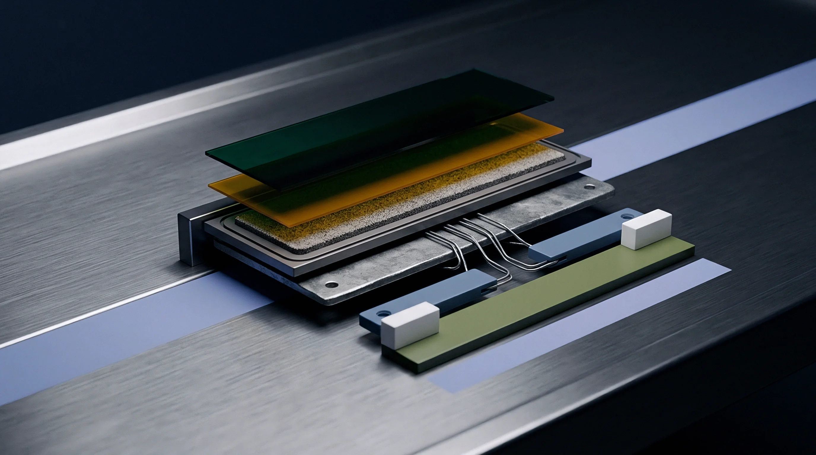
Current streamlines condense as charge carriers flow through discrete micro-contact spots scattered across an otherwise non-conductive interface gap. This spatial contraction introduces constriction resistance, an additional electrical and ionic impedance component caused strictly by geometry rather than material bulk resistivity. Spreading resistance creates local overpotentials.
In solid-state batteries, constriction resistance adds directly to charge transfer impedance, dominating total cell internal resistance when micro contact area ratios fall below critical thresholds.
Spreading Resistance in Dual Electronic and Ionic Transport
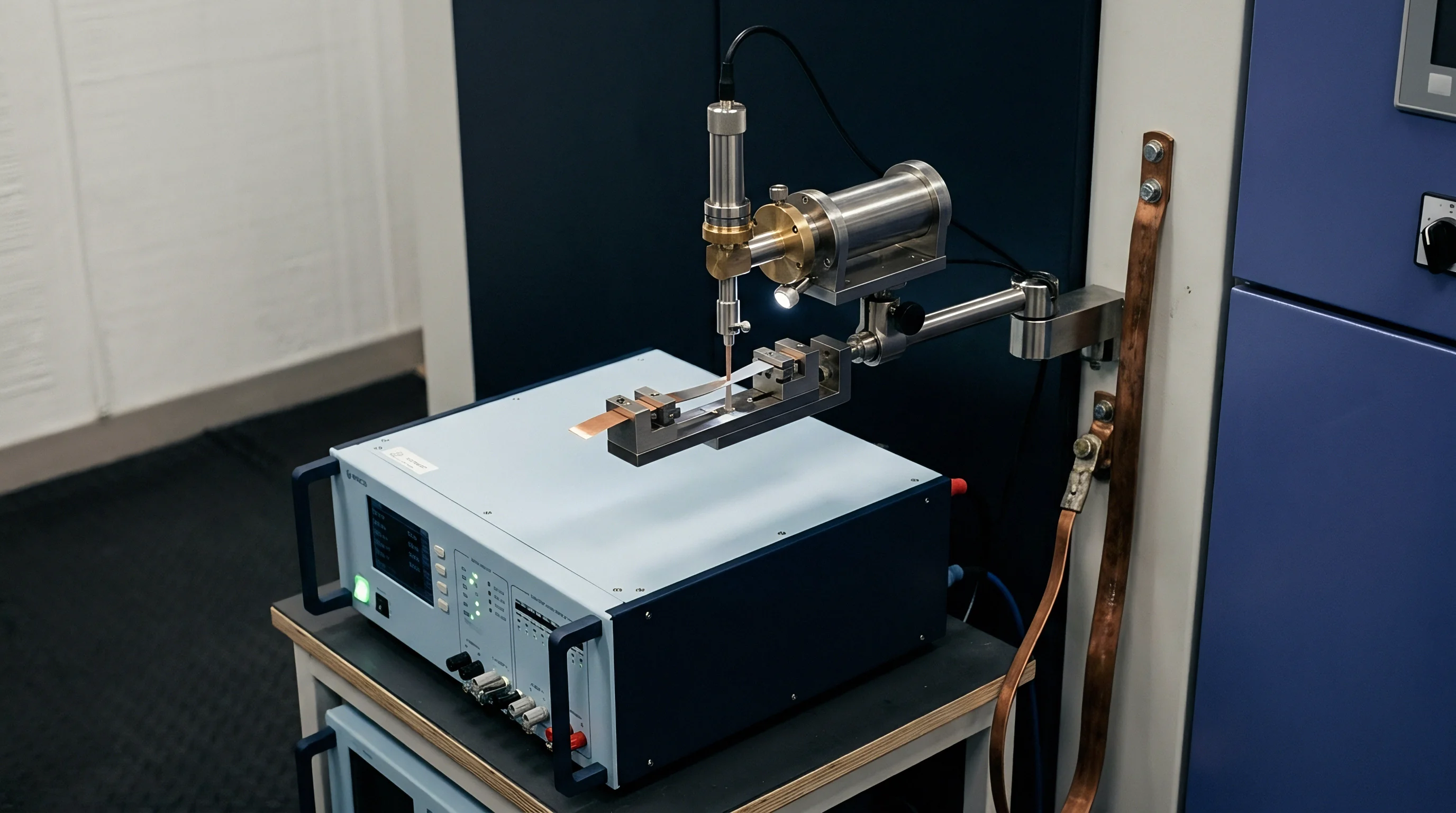
Electrical and ionic conduction across solid-state boundaries obeys classical Holm constriction theory, adjusted for ionic transport mechanisms in solid electrolytes. The constriction resistance of a single circular micro-contact spot depends inversely on the radius of the contact spot and the bulk ionic or electronic conductivity of the adjacent media. For an array of N micro-contacts with average radius a distributed uniformly across an interface, current lines interact when contact spots sit close together.
Constriction resistance formulas account for both independent spreading at small contact fractions and mutual interference at high contact fractions. When micro contact area fraction is small, individual spot constriction resistance scales as the inverse of the contact spot radius. As stack pressure forces contact spot enlargement, adjacent current tubes overlap, modifying total spreading impedance toward zero as real contact area approaches 100 percent of geometric area.
At a real contact area fraction of 12 percent under 5 MPa load, sulfide solid interfaces exhibit a constriction resistance of 18.5 ohm square centimeters at ambient temperature.

Interfacial Impedance Scaling across Partial Contact Areas
Electrochemical impedance spectroscopy isolates the high-frequency response associated with constriction resistance from bulk electrolyte resistance and charge transfer kinetics. Partial physical contact alters the high-frequency Nyquist plot arc, shifting the ohmic intercept and widening interfacial impedance semicircles. Micro contact area restrictions force lithium ions through narrow conduction channels, generating localized overpotentials during high-rate discharge.
| Electrolyte Class | Bulk Ionic Conductivity (mS/cm) | Applied Stack Pressure (MPa) | Real Contact Area Fraction (%) | Mean Contact Spot Radius (µm) | Calculated Constriction Resistance (Ω·cm²) |
|---|---|---|---|---|---|
| Sulfide (Li6PS5Cl) | 2.5 | 1.0 | 8.0 | 0.35 | 38.2 |
| Sulfide (Li6PS5Cl) | 2.5 | 5.0 | 22.0 | 0.82 | 11.4 |
| Oxide (LLZO) | 0.8 | 2.0 | 4.5 | 0.18 | 142.0 |
| Oxide (LLZO) | 0.8 | 10.0 | 14.0 | 0.45 | 32.8 |
| Halide (Li3InCl6) | 1.2 | 2.0 | 11.0 | 0.50 | 24.6 |
| Polymer-Ceramic Composite | 0.3 | 0.5 | 35.0 | 1.20 | 18.1 |
Oxide electrolytes exhibit high elastic moduli and high micro-hardness, resisting plastic deformation under moderate loads. Achieving low constriction resistance in oxide-based solid-state cells demands elevated stack pressures or ductile interlayers to expand micro contact radius. Sulfide electrolytes yield more readily under mechanical load, forming larger contact spot radii at reduced operational pressures, which systematically suppresses ionic constriction impedance across the cell stack.
Underestimating spreading resistance at micro-contacts leads to thermal hot spots, localized overpotentials, and premature cell capacity degradation.


Probe
Diagnostic instrumentation quantifies interfacial contact mechanics without destroying the sealed pouch housing or altering internal stack pressure. Measuring real micro contact area inside a functioning cell demands non-destructive characterization tools capable of differentiating physical contact variations from electrochemical kinetic shifts. Advanced acoustic reflectometry, high-resolution impedance spectroscopy, and operando tactile mapping sensors supply quantitative metrics required for stack pressure validation.
Acoustic Reflection Profiling of Mechanical Contact
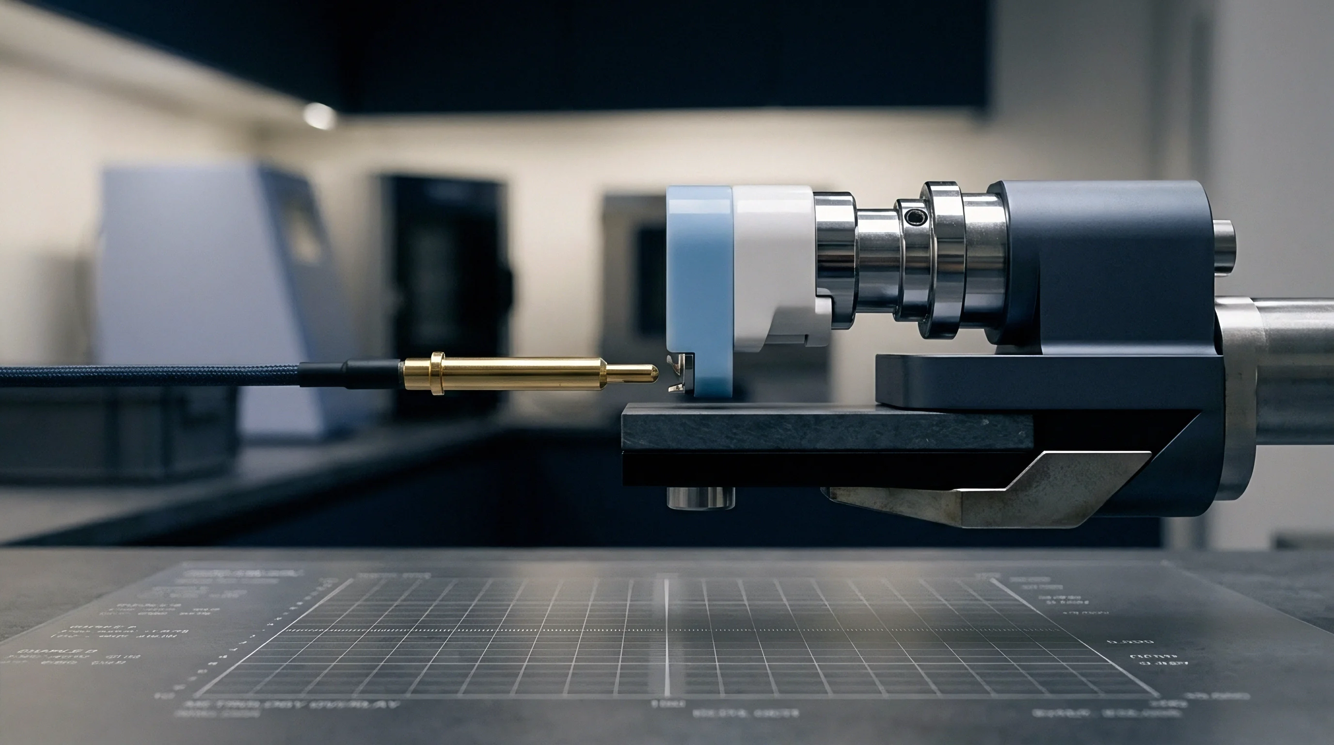
High-frequency transducer pulses pass through external cell packaging and reflect off internal solid-solid boundaries. Acoustic pulses reflect off interfacial gaps. The acoustic reflection coefficient depends directly on the interfacial contact stiffness, which scales linearly with real contact area and applied stack pressure.
Where micro-voids exist, air or vacuum gaps present a massive acoustic impedance mismatch, reflecting ultrasonic signal energy back to the receiver.
Interfacial contact stiffness links transducer reflection amplitude to micro contact area fraction. Operating transducers at frequencies between 10 MHz and 50 MHz delivers spatial resolution sufficient to resolve localized contact non-uniformities across pouch cell surfaces. Calibration against reference polished blocks converts acoustic reflection attenuation maps into absolute real contact area percentage distributions across the active area.
Contact stiffness determines acoustic signal decay. Combining acoustic reflectometry with mechanical load frames enables real-time tracking of contact spot growth during initial cell formation and subsequent pressure modulation steps.
- Calibrate ultrasonic transducer center frequency at 10 MHz against a polished reference block.
- Clamp the solid-state cell in a load frame with in-line piezoelectric load cell verification.
- Record normal acoustic reflection amplitude across a grid of sixty-four raster points.
- Perform multi-frequency EIS sweep from 1 MHz down to 10 mHz under identical temperature equilibrium.
- Apply distribution of relaxation times transformation to isolate high-frequency contact impedance from charge transfer resistance.
In accordance with IEC 62660-3 mechanical testing protocols, uncalibrated pressure distribution across active cell surfaces invalidates cycle life baseline measurements.

Impedance Relaxation Resolution of Micro Interfacial Resistance
Deconvolution of impedance spectra into relaxation times separates ohmic, constriction, and charge-transfer phenomena. The distribution of relaxation times technique resolves overlapping electrochemical processes by transforming frequency-domain impedance data into time-constant domain spectrum peaks. Constriction resistance manifests as a distinct high-frequency peak occurring at characteristic timescales shorter than interphase charge transfer processes.
| Diagnostic Method | Spatial Resolution | Non-Destructive Status | Operando Capability | Primary Output Metric |
|---|---|---|---|---|
| Ultrasonic Reflectometry | 0.5 mm | Non-destructive | Full operando | Interfacial contact stiffness and real area % |
| EIS DRT Analysis | Global stack average | Non-destructive | Full operando | Constriction resistance (Ω·cm²) |
| Piezoresistive Film Matrix | 1.0 mm | Destructive during assembly | Assembly load only | Spatial pressure distribution (MPa) |
| X-ray Computed Tomography | 1.2 µm | Non-destructive | Ex-situ / slow operando | 3D micro-void spatial volume map |
Pressure film records spatial load distribution. Inserting tactile piezoresistive sensor sheets between cell packaging and mechanical endplates maps spatial pressure gradients, identifying edge-loading anomalies caused by rigid housing deflection.
Cell manufacturers routinely attribute initial capacity variance to electrolyte wetting phenomena rather than non-uniform stack pressure distribution across the micro-contact landscape.


Press
Mechanical clamping hardware maintains structural containment while compensating for irreversible volume changes occurring during long-term electrochemical cycling. Solid-state cell chemistries, particularly those using pure lithium metal anodes, undergo continuous volumetric expansion and contraction during plating and stripping phases. Module endplates absorb cyclic swelling force.
Without compliance mechanisms built into the module housing, swelling increases internal stack pressure beyond structural safety limits, or stripping shrinks the anode thickness until micro contact area collapses entirely.

Does Operating Stack Pressure Induce Creep in Solid Electrolyte Interfaces?
Lithium metal under sustained mechanical load deforms over extended timeframes through steady-state mechanical creep. At room temperature, lithium operates at a high homologous temperature, making its yield and creep thresholds highly sensitive to applied pressure and strain rate. Applying continuous stack pressures above 5 MPa induces bulk plastic flow of lithium metal into porous separator structures or around housing boundaries, leading to soft short-circuits or mechanical seal failures.
Sulfide solid electrolytes also exhibit mechanical creep under elevated stack pressures over multi-thousand-hour operational lifetimes. Creep relaxation gradually diminishes internal clamping forces in fixed-volume module enclosures. As internal pressure decays over time, real contact area drops, driving up constriction resistance and triggering accelerated capacity fade during high-rate cycling.
Volumetric swelling during full lithiation transfers mechanical load directly to module tie-rods and housing endplates.

Spring Pack Mechanics and Housing Enclosure Compliance
Designing module endplates demands precise accounting of dynamic force displacement curves. Fixed displacement clamping systems fail because lithium plating increases stack thickness, raising internal force exponentially. Spring-loaded module enclosures utilize Belleville disc spring stacks, wave springs, or engineered elastomeric pads to absorb volume changes while bounding pressure drift within acceptable mechanical limits.
| Clamping Mechanism Type | Thickness Expansion Compensation (mm) | Pressure Drift Band (MPa) | Mass Penalty (% of Pack) | Volumetric Overhead (%) |
|---|---|---|---|---|
| Belleville Spring Stack | 2.5 | ± 0.4 | 6.2 | 8.5 |
| Wave Spring Matrix | 1.8 | ± 0.6 | 4.1 | 5.2 |
| Silicone Elastomer Foam | 1.0 | ± 1.2 | 1.8 | 3.1 |
| Active Pneumatic Bladder | 5.0 | ± 0.05 | 12.5 | 14.0 |
- Initial load margin establishes the minimum factory compression required to maintain baseline contact area at full cell discharge state.
- Thermal expansion compensation prevents thermal excursion events from driving housing structural stresses past material elastic limits.
- Enclosure mass penalty trades structural frame stiffness against system-level gravimetric energy density targets.
- Module deflection limits bound structural bending across endplates to maintain uniform pressure across outer cell edges.
Format selection fixes mechanical tooling costs. Pouch formats demand continuous planar clamping frames to hold stack pressure across large active surface areas. Prismatic rigid cans utilize internal spring structures or pressurized internal gas volumes, shifting the structural load burden from external module frames to cell-level enclosure walls.
Whether self-adjusting shape memory alloy fasteners can maintain constant interfacial load across ten thousand thermal cycles remains unproven in high-volume pack deployments.


Seam
Commercial agreements assign technical responsibilities between cell manufacturers, module packagers, and system integrators at specific physical boundaries. Format choices dictate where mechanical load systems reside. Choosing pouch solid-state cells places the entire stack pressure delivery system inside the module integrator scope, requiring dedicated tooling, endplates, and spring assemblies.
Selecting rigid prismatic formats places stack pressure management inside the cell manufacturer boundary, increasing cell unit price while reducing module assembly complexity.

Format Selection Impact on Pack Mechanical Ownership
Pouch formats demand external mechanical clamping. The module house designs, buys, and warranties the clamping frame, endplates, and springs needed to maintain 5 MPa operational pressure across cell lifetimes. Initial load tests verify spring rates.
Failure of the external clamping fixture to hold required pressure directly causes interfacial contact loss, raising constriction resistance and voiding cell manufacturer cycle-life warranties.
Prismatic formats integrate internal compression mechanisms within the welded aluminum can. The cell vendor assumes full design and warranty liability for micro-contact retention over life, absorbing tooling non-recurring engineering costs inside cell unit pricing. Custom cylindrical solid-state formats utilize central axial tie-rods, distributing stack pressure radially and axially within individual cell shells, though with gravimetric energy density trade-offs.

Tooling Amortization and Warranty Seams for Clamped Cell Modules
Non-recurring engineering expenses for precision spring clamping frames and high-stiffness endplates scale steeply with production volume. Tooling amortizations for cast or stamped aluminum module endplates require upfront commitments before cell mechanical swell profiles are fully characterized across multi-year field cycles.
- Pressure mapping certificates confirm that incoming cell batches meet surface planarity specifications prior to module integration.
- Creep rate tolerances define acceptable stack pressure decay thresholds over calendar aging periods under contractual storage conditions.
- End-of-life deflection boundaries establish maximum allowable module expansion parameters before mechanical warranty claims activate.
- Warranty seam definitions explicitly assign capacity loss caused by pressure drift to either module mechanical hardware or cell electrochemical degradation.
Warranty terms depend on pressure logs. System integration RFQs mandate integrated strain gauge or load cell telemetry inside module housing assemblies to continuous log pressure history throughout pack operation.
Standard supply agreement clause 14.2 shifts warranty liability to the pack integrator if external stack pressure drifts outside the specified 3.5 to 5.0 MPa window during operation.


Dossier
Quality assurance records capture incoming cell verification parameters, mechanical pre-load calibration logs, and compliance documentation required for series production. Validating micro contact area stability across thousands of manufactured units demands standardized testing protocols executed at receiving inspection and factory acceptance stages.

Incoming Quality Metrics for Contact Uniformity
Factory acceptance protocols evaluate batch uniformity through non-destructive acoustic screening and precision thickness mapping. Incoming pouch cells undergo automated laser line profilometry to measure surface thickness variance across active areas. Cells exhibiting thickness non-uniformities greater than 15 micrometers are rejected, as surface height variations generate localized pressure points and uncontacted valleys when compressed between rigid module plates.
Acoustic reflectivity screening at receiving dock incoming inspection identifies internal delamination voids before cells enter module assembly lines. Automated ultrasonic gantries map acoustic attenuation across 100 percent of cell active surfaces within sixty-second cycle times, generating a digital contact uniformity index for every serial number.

Longitudinal Compliance Audits for Pressurized Pack Deliveries
Batch traceability files log the initial baseline stack pressure, spring displacement measurements, and ambient temperature recorded during module mechanical sign-off. Compliance audits require random sampling of assembled modules subjected to thermal shock cycling according to UN 38.3 transport safety requirements and IEC 62660-3 reliability standards. Post-test acoustic mapping verifies that thermal expansion cycles have not degraded internal contact area ratios below quality thresholds.
Complete documentation of micro-contact mechanics ensures that pack-level performance meets rigorous energy density and cycle stability targets throughout the commercial product lifecycle.