Sodium Ion Hard Carbon Anode Specification and Synthesis
Hard carbon anode selection balances d002 spacing above 0.37 nm, BET area under 3 m2/g, and calender density below 1.05 g/cm3 to secure 88% initial efficiency.


Grain
Sodium ions have an ionic radius of 1.02 angstroms, roughly fifty-five percent larger than lithium ions. Graphite rejects sodiation under ambient thermodynamic conditions because the formation energy of binary sodium-graphite intercalation compounds remains positive, peaking around stage-one NaC64 rather than forming stable stage-one NaC6. Hard carbon overcomes this transport limitation through turbostratic graphite domains interspersed with randomized micropores, yielding a standard reversible specific capacity between 280 mAh/g and 350 mAh/g under typical 0.1C galvanostatic conditions.
Hard carbon storage operates across a distinct two-segment voltage profile. The sloping region between 1.20 V and 0.10 V versus Na/Na+ comes from sodium inserting between expanded graphene sheets with interlayer spacing greater than 0.37 nanometers. Below 0.10 V down to 0.01 V, the flat plateau region corresponds to sodium filling closed structural voids.
Cell designers balance slope and plateau capacities according to expected pack duty cycles. High-rate urban mobility applications favor materials with sixty percent or more slope capacity because intercalation kinetics outpace pore desolvation. Stationary systems prioritize extended low-voltage plateau capacity to maximize full-cell working voltage when paired with Prussian blue analogues or sodium transition-metal layered oxides.
Pores smaller than 0.5 nanometers prevent solvent co-intercalation while preserving sodium cluster aggregation during the low-voltage plateau.
Defect density controls initial coulombic efficiency. Open micropores, residual surface oxygen complexes, and broken sp2 edge bonds consume sodium during the first formation cycle to build the solid electrolyte interphase. Surface area measured by Brunauer-Emmett-Teller nitrogen adsorption must stay within tight production windows.
Uncoated hard carbons with specific surface areas above 8.0 m2/g routinely yield initial coulombic efficiencies below eighty percent. Production-grade materials maintain surface areas between 1.5 m2/g and 4.0 m2/g, pushing initial coulombic efficiency above eighty-seven percent in commercial coin and pouch evaluations.
| Parameter | Analytical Method | Entry Grade Target | Premium Commercial Target | Rejection Threshold |
|---|---|---|---|---|
| Interlayer Spacing (d002) | X-Ray Diffraction (Cu K-alpha) | 0.365 to 0.375 nm | 0.378 to 0.390 nm | < 0.360 nm |
| Specific Surface Area | BET Nitrogen Adsorption (77 K) | 4.0 to 6.5 m2/g | 1.2 to 3.0 m2/g | > 8.0 m2/g |
| Median Particle Size (D50) | Laser Diffraction (ISO 13320) | 6.5 to 10.5 µm | 4.5 to 8.0 µm | > 14.0 µm |
| Initial Coulombic Efficiency | 0.1C to 0.005 V vs Na/Na+ | 82.0 to 86.0 % | 88.0 to 92.5 % | < 80.0 % |
| Reversible Capacity | 0.1C Galvanostatic (25 °C) | 270 to 295 mAh/g | 310 to 355 mAh/g | < 260 mAh/g |
| Tap Density | Tapped Volume (ASTM B527) | 0.85 to 0.95 g/cm3 | 0.98 to 1.15 g/cm3 | < 0.80 g/cm3 |
Microstructural morphology introduces specific vulnerabilities during cell manufacturing.
- Excessive internal closed porosity reduces particle skeletal density below 1.50 g/cm3, dropping volumetric energy density below viable pack thresholds.
- Residual heteroatom surface content accelerates parasitic side reactions with fluoroethylene carbonate additives, exhausting electrolyte over extended cycling.
- Agglomerated secondary grains fracture under calender roll pressure, exposing raw carbon planes that restart solid electrolyte interphase formation.
Ignoring tap density and skeletal density leads to cell sizing errors, forcing engineers to enlarge module dimensions and absorb warranty exposure from volumetric density shortfalls.

Kiln
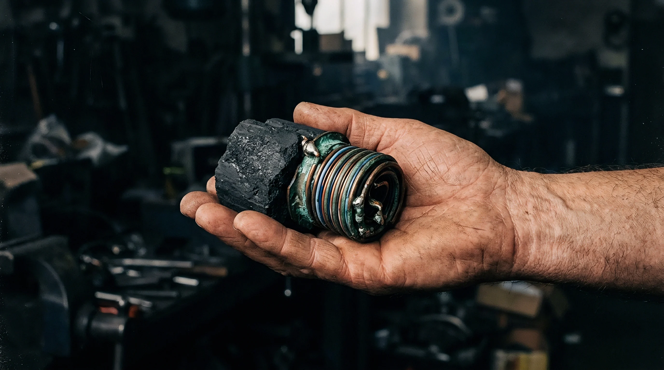
Hard carbon synthesis depends on preventing graphitization at high temperatures through precursor selection and controlled crosslinking. Unlike pitch or petroleum coke precursors that soften and order into graphite above 2000 °C, non-graphitizing feedstocks feature crosslinked polymer networks with oxygen, nitrogen, or sulfur bridges that lock disordered aromatic domains in place. Precursors generally come from three industrial streams: biomass carbohydrates, synthetic polymers, and fossil-derived pitches modified by chemical oxidation.
Biomass precursors such as sucrose, coconut shells, and lignin need intensive chemical deashing to remove inorganic oxides. Alkali metals and silica in raw biomass trigger catalytic graphitization, shrink d002 interlayer spacing, and create macropores that impair electrochemical performance. Acid leaching brings ash levels below three hundred parts per million.
Synthetic polymers like polyacrylonitrile and phenolic resins give consistent carbon matrices with zero ash contamination, though synthesis costs run four to six times higher than agricultural streams.
Thermal carbonization uses two continuous furnace steps: low-temperature stabilization followed by high-temperature carbonization. Stabilization takes place between 250 °C and 450 °C in air or lean oxygen. This stage drives oxidative crosslinking, creating oxygen bridges that prevent particle fusion and bubbling.
High-temperature carbonization follows between 1100 °C and 1400 °C under inert nitrogen or argon.

How Carbonization Temperature Governs Interlayer Spacing?
High-temperature setpoints determine the ratio of graphitic sheets to closed internal pores. Processing at 1000 °C leaves uncarbonized hydrocarbon fragments and abundant surface functional groups, driving up specific surface area and depressing initial coulombic efficiency. Raising the kiln temperature to 1300 °C removes heteroatoms, merges aromatic clusters, closes surface pores, and shrinks the d002 lattice toward 0.372 nanometers.
Heating beyond 1500 °C induces structural ordering, collapsing closed pore volume and reducing sodium storage capacity.
| Kiln Zone | Temperature Range | Atmosphere | Residence Time | Dominant Structural Mechanism | Carbon Yield |
|---|---|---|---|---|---|
| Hydrothermal Carbonization | 180 to 240 °C | Autogenous Water Vapor | 4.0 to 12.0 h | Dehydration, aromatization into carbonaceous microspheres | 55 to 70 % |
| Oxidative Stabilization | 250 to 400 °C | Compressed Dry Air | 1.5 to 3.0 h | Thermosetting via ether and carbonyl crosslink formation | 85 to 92 % |
| Intermediate Pyrolysis | 600 to 900 °C | Purified Nitrogen (>99.999%) | 2.0 to 4.0 h | Volatile organic compound stripping, tar expulsion | 40 to 50 % |
| Final Calcination | 1150 to 1350 °C | Inert Argon or Nitrogen | 1.0 to 3.0 h | Aromatic domain enlargement, micropore closure | 82 to 88 % |
| Chemical Vapor Deposition | 700 to 900 °C | Methane / Inert Carrier | 0.5 to 1.5 h | Pyrolytic carbon deposition sealing remaining open pores | 96 to 99 % |
To close open micropores that degrade coulombic efficiency, commercial processors apply chemical vapor deposition to calcined hard carbon. Injecting volatile hydrocarbons like methane, toluene, or ethanol into a rotary kiln at 800 °C deposits a thin pyrolytic carbon skin over the particles. This seal blocks nitrogen adsorption at 77 K while permitting sodium ion transport during charge transfer.
Kiln operators verify synthesis parameters against engineering checklists before releasing material lots.
- Residual oxygen index below 1.2 weight percent confirmed via inert gas fusion elemental analysis.
- Furnace oxygen leakage rate below ten parts per million inside the calcination zone to prevent surface etching.
- Exhaust scrubber tar concentration monitored continuously to confirm complete devolatilization of heavy aromatics.
- Rotary tube rotation speed calibrated within three percent of target to ensure uniform thermal exposure across the bed depth.
Balancing feedstock purity against kiln residence time prevents uncarbonized core defects without driving energy costs beyond viable thresholds.
Slurry
Hard carbon powders show distinct rheological behavior during aqueous mixing because of their irregular morphology and low density. Unlike spherical synthetic graphite, hard carbons made from milled biomass or resin precursors have high aspect ratios and sharp edges. These geometric traits change shear-thinning behavior in dual-planetary mixers, requiring careful adjustment of water-soluble binders to maintain stable suspensions without exceeding viscosity limits.
Carboxymethyl cellulose paired with styrene-butadiene rubber forms the standard aqueous binder system. Carboxymethyl cellulose controls viscosity and dispersion stability, while styrene-butadiene rubber provides elasticity and adhesion to the aluminum current collector foil. Sodium batteries use aluminum foil at the anode rather than copper because sodium does not alloy with aluminum at low potentials, saving on bill-of-materials costs.
Foils range from 10 to 15 micrometers thick, demanding strong coating adhesion to withstand web tension during roll-to-roll processing.
Aqueous polyacrylic acid binders neutralize localized swelling stresses better than elastomeric rubber emulsions during sodium insertion.
Polyacrylic acid is increasingly replacing styrene-butadiene systems in high-plateau electrodes. Carboxylic acid side groups along the polyacrylic chain interact with surface hydroxyl and carboxyl sites on the carbon particles, forming mechanical anchors that prevent delamination during expansion. Hard carbon expands by eight to twelve percent during sodiation ~ a volume change similar to graphite during lithiation, but one that creates higher shear stress at the foil interface because sodium aggregates within localized plateau voids.
Slurry preparation relies on strict operational sequencing to keep particles dispersed.
- Dry mixing hard carbon powder and conductive additive under high shear for thirty minutes.
- Dissolving carboxymethyl cellulose in deionized water at three percent solids until clear.
- Adding the conductive dry mix to the binder solution under vacuum below negative ninety-five kilopascals.
- High-speed dispersion with saw-tooth impellers at four thousand revolutions per minute for ninety minutes.
- Blending in styrene-butadiene rubber emulsion under low shear to preserve polymer chains.
- Degassing the slurry and filtering through a fifty-micrometer mesh to catch unbonded agglomerates.
Coating lines apply the degassed slurry to treated aluminum foil at mass loadings between 3.5 and 7.0 mg/cm2, giving areal capacities of 1.0 to 2.2 mAh/cm2. Drying occurs in multi-zone convection ovens where air speed and temperature profiles are staged to prevent binder migration. If the surface dries too fast, evaporating water draws dissolved carboxymethyl cellulose upward, stripping binder from the foil interface.
Calendering hard carbon electrodes requires care. Synthetic graphite can be compacted to 1.70 g/cm3 without severe grain damage, but hard carbon particles are hard and brittle, with internal void structures that collapse under high pressure. Compacting beyond 1.15 g/cm3 fractures primary particles, ruptures chemical-vapor-deposited coatings, exposes internal micropores to electrolyte, and ruins cycling stability.
Production lines keep calender densities between 0.90 and 1.05 g/cm3.
Batch-to-batch slurry viscosity variations usually stem from seasonal moisture swings in incoming raw carbon precursors.


Drift
Capacity fade in sodium-ion hard carbon anodes depends on cut-off voltages, electrolyte breakdown, and interface growth. Sodium plating is the primary failure mode during fast charging and low-temperature operation. Because the plateau sodiation potential lies between 0.08 V and 0.005 V versus Na/Na+, minor overpotential shifts from cell impedance or cold temperatures drop the potential below zero volts, triggering metallic sodium deposition on the carbon surface.
Where Does Irreversible Capacity Loss Concentrate?
Irreversible sodium loss occurs mainly in the solid electrolyte interphase and deep, closed pores. On early cycles, electrolyte solvents decompose into an inorganic-organic surface film. Standard NaPF6 in carbonate solvents creates an interphase containing sodium fluoride, sodium carbonate, and alkyl carbonates.
Sodium fluoride provides mechanical strength and low electronic conductivity, while organic alkyl carbonates supply flexibility to handle volume changes during cycling.
| Solvent Blend | Salt System | Key Additive | First Cycle Efficiency | Cycle Retention (1000 Cycles) | Dominant Decomposition Product |
|---|---|---|---|---|---|
| Ethylene Carbonate / Propylene Carbonate (1:1) | 1.0M NaPF6 | None | 76.5 % | 58.0 % | Alkyl dicarbonate polymers, Na2CO3 |
| Propylene Carbonate | 1.0M NaPF6 | 2.0 wt% Fluoroethylene Carbonate | 84.2 % | 83.5 % | Amorphous sodium fluoride, polyfluorinated esters |
| Ethylene Carbonate / Diethyl Carbonate (1:1) | 1.0M NaClO4 | None | 79.0 % | 64.0 % | Sodium chlorate fragments, organic ethers |
| Diglyme (Diethylene Glycol Dimethyl Ether) | 1.0M NaFSI | None | 89.5 % | 91.0 % | Inorganic NaF, Na2SO3, Na2O thin film |
| Propylene Carbonate / Ethyl Methyl Carbonate | 1.0M NaPF6 | 1.0 wt% Sodium Difluorophosphate | 86.8 % | 87.2 % | Fluorinated phosphates, dense NaF layer |
Fluoroethylene carbonate is a critical additive in carbonate formulations. Its decomposition forms a uniform sodium fluoride layer that stops solvent co-intercalation. Additive consumption speeds up at elevated temperatures; above 45 °C, acidic species dissolve the fluoride film, driving continuous interphase growth, rising cell impedance, and depletion of active sodium from the cathode.
Ether electrolytes, such as diglyme and tetraglyme blends, offer exceptional interface stability on hard carbon. Sodium ions coordinate with ether molecules into solvent-separated pairs that desolvate rapidly at the surface, forming thin, conductive inorganic interphases. These systems maintain good low-temperature performance, holding eighty percent capacity at negative twenty degrees Celsius.
Carbonates, however, remain cheaper and offer better oxidative stability above 4.0 V against layered oxide cathodes.
A thick, disorganized passivation layer drives cell internal impedance upward long before cathode structural collapse occurs.
Sodium pore-filling during the low-voltage plateau generates internal stress. Trapped sodium clusters inside closed voids press against the surrounding graphene walls. Over repeated cycles, this causes microstructural fatigue, leading to pore collapse, lost plateau capacity, and trapped sodium that cannot be extracted on desodiation.
Whether non-destructive acoustic time-of-flight testing can distinguish internal pore collapse from interphase growth during field aging remains uncertain on pilot testing lines.
Lot
Procuring battery-grade hard carbon requires thorough technical verification to guard against unfunctionalized feedstocks and variable lot quality. Raw biomass sources, including agricultural husks and industrial byproducts, show regional variations in mineral content, moisture uptake, and polymer crosslinking. Sourcing teams rely on multi-tier quality frameworks to ensure incoming lots match lab benchmarks.
Raw material costs strongly influence cell pricing. Hard carbon powders trade between six and twelve US dollars per kilogram at scale, accounting for eight to fifteen percent of total cell manufacturing costs. Prices are expected to drop toward four dollars per kilogram as synthetic carbohydrate and pitch supply lines expand to multi-gigawatt-hour capacities.
Synthesis costs remain tied to high-temperature kiln operation, where electricity accounts for forty percent of processing expense.
Incoming inspections verify material quality before carbon is transferred to production silos. Quality teams sample shipping containers according to international standards, checking that moisture stays below five hundred parts per million by Karl Fischer titration, verifying zero magnetic iron content with inline separators, and confirming particle size limits through laser scattering.
Trace metals pose direct short-circuit risks. Iron, copper, and chromium particles in carbon lots dissolve at anode operating potentials and migrate across the separator, forming metallic dendrites on the cathode. Sourcing specifications set strict impurity limits, capping total magnetic contamination below twenty parts per billion.
Supply contracts use IEC 61960-3 test protocols for capacity retention, requiring incoming carbon lots to achieve at least eighty-five percent initial coulombic efficiency in benchmark coin cells before warehouse release.