Laboratory Qualification Protocols for Low Temperature Battery Pack Thermal Design
Sub-zero thermal qualification requires precise soak verification, active heating uniformity controls, and three-electrode plating boundary detection.


Soak
Sub-zero exposure shifts the chemical equilibrium inside commercial lithium-ion cells well before any load is drawn. At -20°C, the dynamic viscosity of common organic liquid electrolytes jumps high enough to drop bulk ionic conductivity by up to two orders of magnitude against 25°C baselines. Lithium ions face steep activation energy barriers when shedding their solvation shells at the electrode-electrolyte interface.
As a result, charge-transfer resistance across the solid electrolyte interphase surges, making interfacial transfer ~ rather than solid-state diffusion through the active material ~ the rate-limiting kinetic step.
Standard laboratory thermal tests that ignore core-to-surface thermodynamic equilibrium generate misleading operational data. Outer pouches and aluminum cans track chamber air changes far more quickly than dense jellyrolls or electrode stacks can follow. Running a test before the internal core stabilizes introduces thermal gradients across the cell, distorting the measured voltage response and obscuring genuine charge-transfer impedance.

Electrolyte Viscosity and Desolvation Energy Barriers
Electrolyte formulation sets the cold-temperature boundary for cell operation. Conventional carbonate mixtures of ethylene carbonate, dimethyl carbonate, and ethyl methyl carbonate stiffen or begin partial phase separation as temperatures drop below -10°C. Ethylene carbonate freezes near 36°C, so formulators rely on tailored co-solvent balances and fluorinated low-viscosity additives to prevent phase separation under freezing conditions. As bulk viscosity rises, the solvation sheath clings to each lithium ion; stripping that shell so the ion can enter a graphite or silicon-composite anode demands significant overpotential, which appears as a sharp initial voltage drop during discharge pulses.
- Position the instrumented battery module within the environmental test chamber on an thermally isolated composite rack to eliminate conductive sink effects.
- Connect surface and core thermocouple sensors across central and peripheral cells to monitor internal thermal convergence.
- Lower chamber temperature to the targeted minimum qualification point at a controlled rate not exceeding 1°C per minute.
- Maintain the target sub-zero temperature environment for a minimum soak window of six hours after casing thermocouples reach thermal equilibrium.
- Perform electrochemical impedance spectroscopy across a frequency band of 10 kHz to 10 mHz to extract bulk resistance and charge-transfer parameters before initiating load cycles.
Thermodynamic Equilibration Timelines in Sub-Zero Media
Thermal transport through multi-layer cell builds is strongly anisotropic. Heat travels up to twenty times faster along copper and aluminum current collector foils than across porous separator layers and coated active materials. For prismatic cells above 100 Ah, complete thermal stabilization takes sustained soaking.
Surface thermography alone is unreliable here, because core temperatures lag skin readings by hours depending on enclosure mass, potting density, and internal structural foam.
At -20°C ambient exposure, a 150 Ah prismatic LFP cell exhibits a 78 percent increase in charge-transfer impedance prior to thermal stabilization, requiring eight hours of continuous soak time to reach electrochemical equilibrium.
Measuring open-circuit cell voltage the moment a chamber reaches its setpoint yields inflated resistance values that misstate steady-state behavior. Reliable thermal qualification requires monitoring real impedance over time until drift settles below 0.5 percent between consecutive three-hour readings. Electrical characterization must wait until that baseline is fully established.


Plating
Anodic lithium plating is the primary catastrophic failure mode when charging cells in sub-zero environments. Under current, cold graphite anode potentials easily dip below 0 V relative to Li/Li+. Thermodynamically, solvated lithium ions then reduce directly into metallic deposits across the graphite surfaces instead of intercalating into the lattice.
The resulting metallic dendrites consume active lithium inventory, break down liquid electrolyte through parasitic side reactions, and can pierce separators.
Pinpointing when metallic plating begins under test conditions demands dedicated diagnostic methods, as two-electrode terminal measurements cannot separate anode surface potential from total cell polarization.
Anode Overpotential and Lithium Deposition Dynamics
Cell polarization during low-temperature charging breaks down into ohmic resistance, charge transfer overpotential, and mass transport resistance. Below 0°C, desolvation resistance sharply drives up the charge-transfer overpotential at the graphite anode. If current delivery outpaces intercalation kinetics, excess electrons collect at the graphite interface, dragging local potential below the threshold for metallic reduction.
Once plating begins, the deposits redistribute local current density, producing hot spots and accelerating degradation across subsequent cycles.
| Chemistry Type | Test Temperature (°C) | Max Safe C-Rate | Anode Potential vs Li/Li+ (mV) | Plating Onset Window (SoC %) |
|---|---|---|---|---|
| LiFePO4 / Graphite | -10 | 0.15 C | +12 mV | 72 – 100 % |
| LiFePO4 / Graphite | -20 | 0.03 C | +4 mV | 45 – 100 % |
| NMC 811 / Graphite-Silicon | -10 | 0.20 C | +18 mV | 68 – 100 % |
| NMC 811 / Graphite-Silicon | -20 | 0.05 C | +2 mV | 38 – 100 % |
| NMC 811 / Graphite-Silicon | -30 | 0.01 C | -5 mV (Plating) | 12 – 100 % |

Three-Electrode Diagnostic Arrays for Sub-Zero Profiling
Establishing safe operating windows for sub-zero charging requires three-electrode test cells. Embedding a reference electrode ~ typically metallic lithium or lithium titanate ~ allows direct, independent tracking of working anode and cathode potentials. Test channels record exactly when anode potentials drop beneath zero volts under varied C-rates and thermal conditions.
Non-destructive techniques like post-charge differential voltage analysis (dV/dQ) and open-circuit voltage relaxation curves then reveal the chemical re-intercalation of stripped lithium while the cell rests.
Battery management systems often rely on lookup tables indexed to ambient temperature to prevent plating, but localized thermal gradients and current crowding can trigger regional plating well before pack-level sensors signal a violation.

Heater
Battery packs deployed in sub-zero environments rely on active heating systems to bring cells into acceptable operational windows before high-rate charging or heavy discharge begins. Integrators turn to etched-foil polyimide heaters, PTC ceramic elements, or liquid glycol plates depending on thermal targets. That selection dictates warm-up speeds, parasitic mass, intra-cell thermal stress, and overall pack complexity.
Poorly routed heating elements create steep thermal gradients across cell bodies, causing uneven internal resistance, localized aging, and premature cell retirement.
Convective and Conductive Warm-Up Circuit Design
Conductive polyimide film heaters applied directly to cell faces transfer thermal energy efficiently. Even so, uneven clamp pressure or voids in thermal interface materials create localized air gaps, producing heater hot spots and burning out elements prematurely. Water-glycol fluid circuits distribute heat more evenly across larger modules, but add pumps, valves, and leak risks that complicate system validation.

Localized Thermal Gradients across Large-Format Prismatic Cells
Injecting high heat flux into frozen cells induces severe internal mechanical stress. As exterior layers warm and expand while the core stays contracted, significant compressive forces develop across internal electrode wraps. Gradients wider than 5°C across a single prismatic unit also distort current distribution during discharge, since current routes preferentially through warmer regions with lower internal resistance.
| Heating Topology | Warm-Up Rate (°C/min) | Max Intra-Cell Delta (°C) | System Efficiency (%) | Mass Penalty (kg/kWh) |
|---|---|---|---|---|
| Polyimide Resistance Film | 1.2 – 2.5 | 6.8 | 88 % | 0.15 |
| AC Internal High-Frequency | 3.0 – 6.0 | 1.5 | 94 % | 0.02 |
| Liquid Glycol Loop | 0.5 – 1.5 | 2.1 | 72 % | 0.85 |
| PTC Ceramic Plates | 1.0 – 2.0 | 4.2 | 82 % | 0.35 |
High-frequency alternating current heating excites internal cell impedance directly, generating volumetric warmth without relying on external thermal conduction. Excitation frequencies between 1 kHz and 5 kHz warm the core uniformly without driving lithium plating. Qualification routines must confirm that prolonged alternating-current conditioning does not break down electrode binder matrices or promote copper dissolution over repetitive sub-zero cycles.
- Thermal Interface Material Stability requires verification of thermal conductivity and mechanical elasticity after 500 thermal freeze-thaw cycles between -40°C and +60°C.
- Heater Element Insulation Resistance must maintain dielectric breakdown resistance above 2500 V DC when subjected to high humidity condensing conditions at sub-zero limits.
- Localized Temperature Uniformity demands that maximum thermal variance across cell surfaces remains below 3.0°C during full-power preheating operations.
- Control Circuit Redundancy relies on dual independent hardware cutoffs to prevent catastrophic thermal runaway events in the event of primary thermistor failure.
Thermal gradient control limits peak temperature variance across individual cell surfaces to less than three degrees Celsius during active preheating from sub-zero conditions.
Failing to balance thermal input across cold pack structures leads to localized cell over-discharge, accelerated regional capacity loss, and premature termination of system warranty coverage.


Qualification
Environmental chamber qualification validates whether pack thermal designs survive operational stress in the field. Standard test profiles subject assemblies to thermal cycling, deep sub-zero soaks, dynamic load schedules, and humidity shifts. Chambers require precise air speed and temperature control, since excessive convective air movement alters boundary-layer cooling and corrupts thermal data.
Environmental qualification programs require strict condensation control strategies during thermal transition phases to ensure safety electrical isolation remains uncompromised.
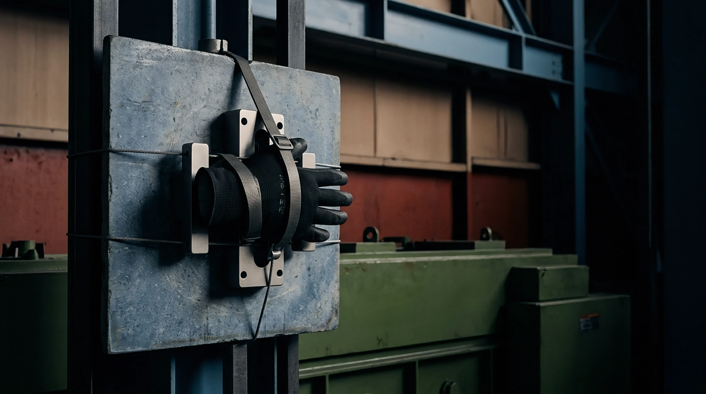
How Do Environmental Chambers Distill Dynamic Cell Heating?
Chamber testing under dynamic electrical loads resolves the balance between internal electrochemical heat generation and external cooling. Under heavy cold discharge, internal I-squared-R losses produce substantial core heat, which drops internal resistance and lifts terminal voltage as discharge proceeds. Chamber control systems must differentiate between heat generated internally by cell kinetics and thermal energy moved by forced airflow to yield repeatable thermal data.

Chamber Ramp Control and Thermal Shock Prevention
Uncontrolled thermal ramps stress pack enclosures, elastomeric seals, and internal busbars. Testing protocols hold ramp rates to 1°C to 2°C per minute to reflect field exposure in automotive and stationary storage applications. Thermal shock testing ~ transferring modules rapidly between extreme cold and warm chambers ~ serves as a destructive screen to expose busbar solder cracks, interface delamination, and enclosure gasket failures.
| Test Protocol | Temperature Range (°C) | Ramp Rate (°C/min) | Electrical Load Profile | Primary Failure Target |
|---|---|---|---|---|
| Thermal Shock (IEC 62660-2) | -40 to +65 | > 30 (Transfer) | Zero Load (Rest) | Seal Fatigue, Mechanical Rupture |
| Low-Temp Capacity Verification | -20 Constant | N/A (Soaked) | 0.2 C Full Discharge | Available Energy Mapping |
| Cold Charge Acceptability | -10 to 0 | 0.5 | Stepwise BMS Profile | Lithium Plating Onset |
| Frosting Condensation Cycle | -20 to +25 | 2.0 | Standby with High Humidity | Short Circuit, Insulation Loss |
Managing chamber humidity prevents condensation on bare busbars and terminals during warm-up steps. Moving cold packs from sub-zero soaks into ambient conditions causes rapid moisture condensation across conductors and electronics. Protocols call for dry nitrogen or dry air purges (dew point below -40°C) to prevent surface tracking currents or internal sensor wire shorts.
- Chamber Air Flow Velocity Calibration verifies that forced air circulation speed does not exceed 1.5 meters per second at the battery module surface to minimize artificial convective heat loss.
- Data Acquisition Channel Synchronization locks thermal sensor readings to electrical load channel data within a 10-millisecond time window for accurate enthalpy calculations.
- Safety Containment Venting Protocols establish automated inert gas purge procedures triggered immediately upon detection of volatile organic compound gasses or abnormal pressure spikes.
- Isolation Resistance Monitoring Requirements continuously record high-voltage bus bar insulation impedance to chassis ground throughout thermal transition steps.
Standard IEC 62660-2 Section 6.2 mandates continuous insulation resistance tracking above 100 ohms per volt across all thermal transition phases to verify moisture seal integrity.
Contracts governing thermal engineering validation require strict compliance with UN 38.3 T2 thermal test profiles, establishing clear legal fault allocations if structural casing failures occur during sub-zero transport verification.
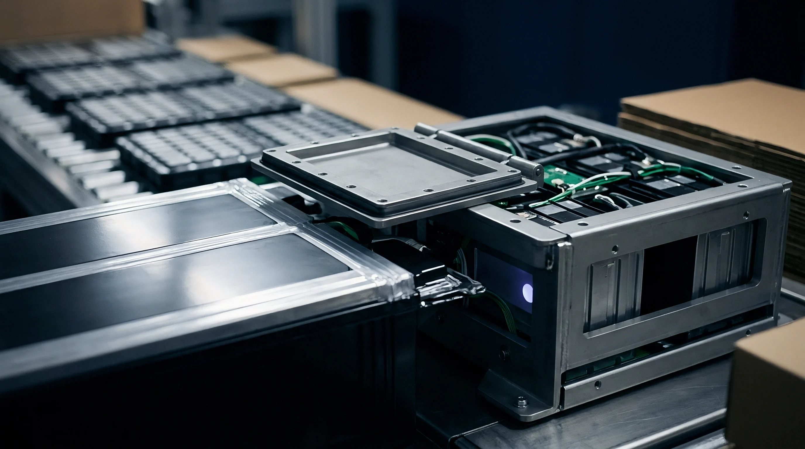

Degradation
Repeated sub-zero cycling accelerates microstructural damage throughout a cell. Irreversible capacity loss accumulates through active lithium consumption during plating, particle fracture from thermal contraction mismatches, and mechanical breakdown of the solid electrolyte interphase. Electrochemical diagnostics must distinguish between temporary capacity dips caused by kinetic sluggishness and permanent cell degradation.
Quantifying permanent capacity degradation requires returning cells to standardized baseline temperatures before recording post-exposure health metrics.

Capacity Fade Mechanisms under Low-Temperature Charge Cycling
Charging below specified temperature limits causes severe, permanent damage. Metallic lithium deposits react with carbonate solvents to produce secondary SEI layers, permanently trapping active lithium and liquid solvent. The outcome is rapid capacity fade accompanied by impedance growth.
Cathode active particles simultaneously undergo mechanical distress, as sharp lithium concentration gradients create intergranular cracks that isolate active material from the conductive matrix.

Solid Electrolyte Interphase Microstructural Evolution
The protective SEI film on graphite particles fractures and rebuilds repeatedly during low-temperature cycling. Volume shifts in the graphite combined with lithium dendrite formation rupture the passivating layer. Electrolyte reaches freshly exposed active surfaces, reacting to form new passivation products that thicken the SEI, drive up cell impedance, and consume electrolyte inventory over time.
- Active Lithium Loss via Plating Side Reactions permanently reduces available discharge capacity through the formation of dead lithium compounds and thick passivating films.
- Cathode Particle Microcracking isolates active electrode material from conductive carbon networks, increasing localized internal resistance and accelerating capacity fade.
- Electrolyte Solvent Depletion increases bulk electrolyte viscosity, raising cold internal impedance and lowering total power capability across cell operational life.
- Separator Pore Clogging caused by decomposed electrolyte species reduces effective ionic porosity, restricting lithium transport during high-rate discharge pulses.
Post-test teardown analysis reveals that continuous sub-zero charge cycling increases solid electrolyte interphase layer thickness by over 200 percent compared to baseline aging at ambient room temperature.
Validation protocols must isolate binder mechanical breakdown from active lithium loss to build reliable multi-year life models.

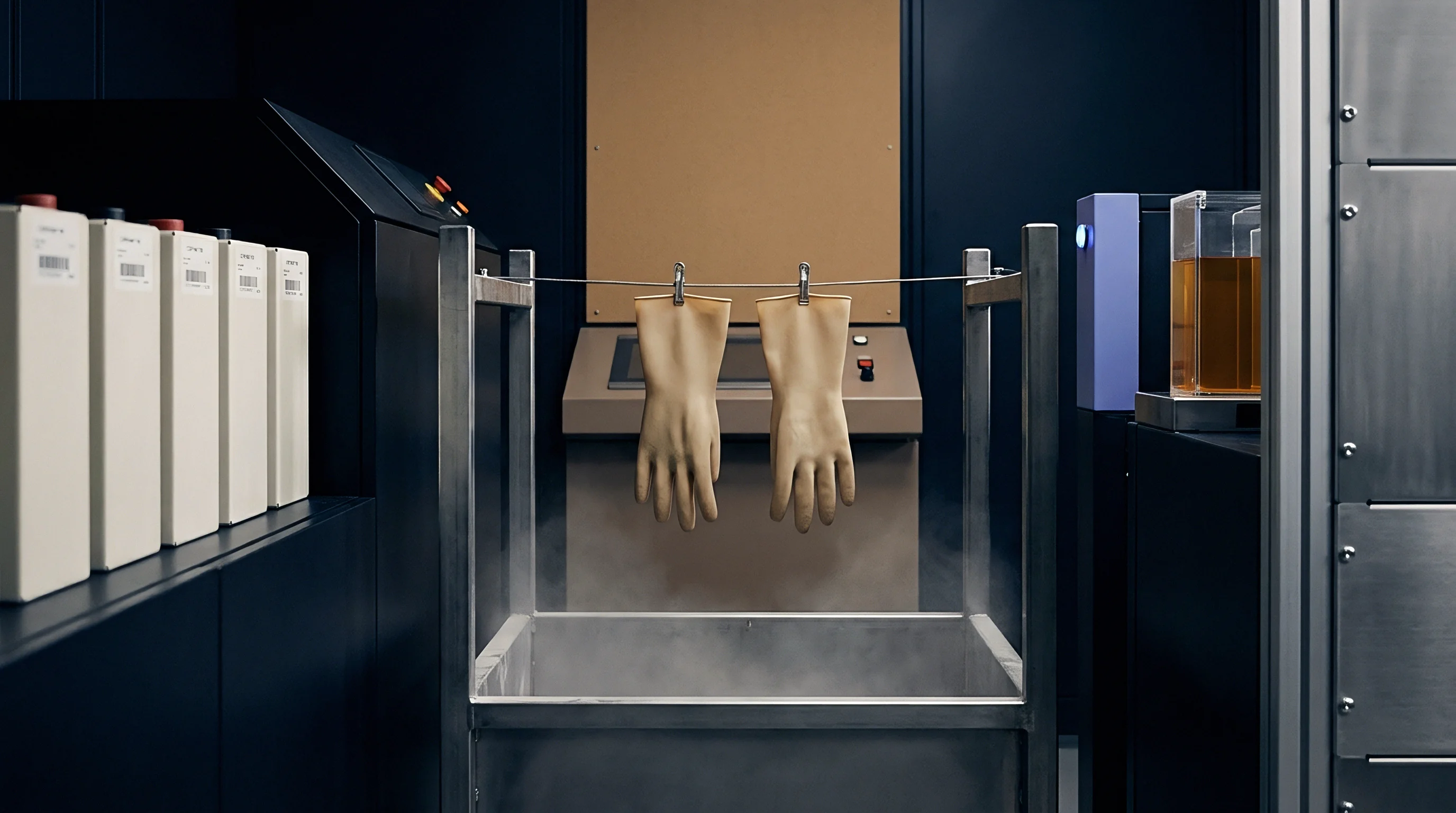
Liability
Commercial contracts linking cell manufacturers, pack integrators, and OEMs depend on rigorously defined thermal operating envelopes. When sub-zero field failures arise, assigning responsibility relies on internal BMS data logs. Supply agreements set explicit temperature limits below which high-rate charging or heavy loads are prohibited without active pre-heating.
Incorporating tamper-proof environmental tracking hardware into battery pack architectures ensures clear allocation of financial risk when low-temperature degradation occurs.

BMS Firmware Lockout Boundaries and Field Telemetry Logs
Modern battery management software applies staged thermal cutoffs to protect packs from low-temperature damage. Core temperatures below 0°C trigger firmware limits on charge acceptance based on mapped safety thresholds. Below -20°C, firmware blocks charging entirely, allowing only pre-heating circuits to draw power.
Validation testing must verify these lockout functions remain enforced across software resets, sensor noise, and restart routines.
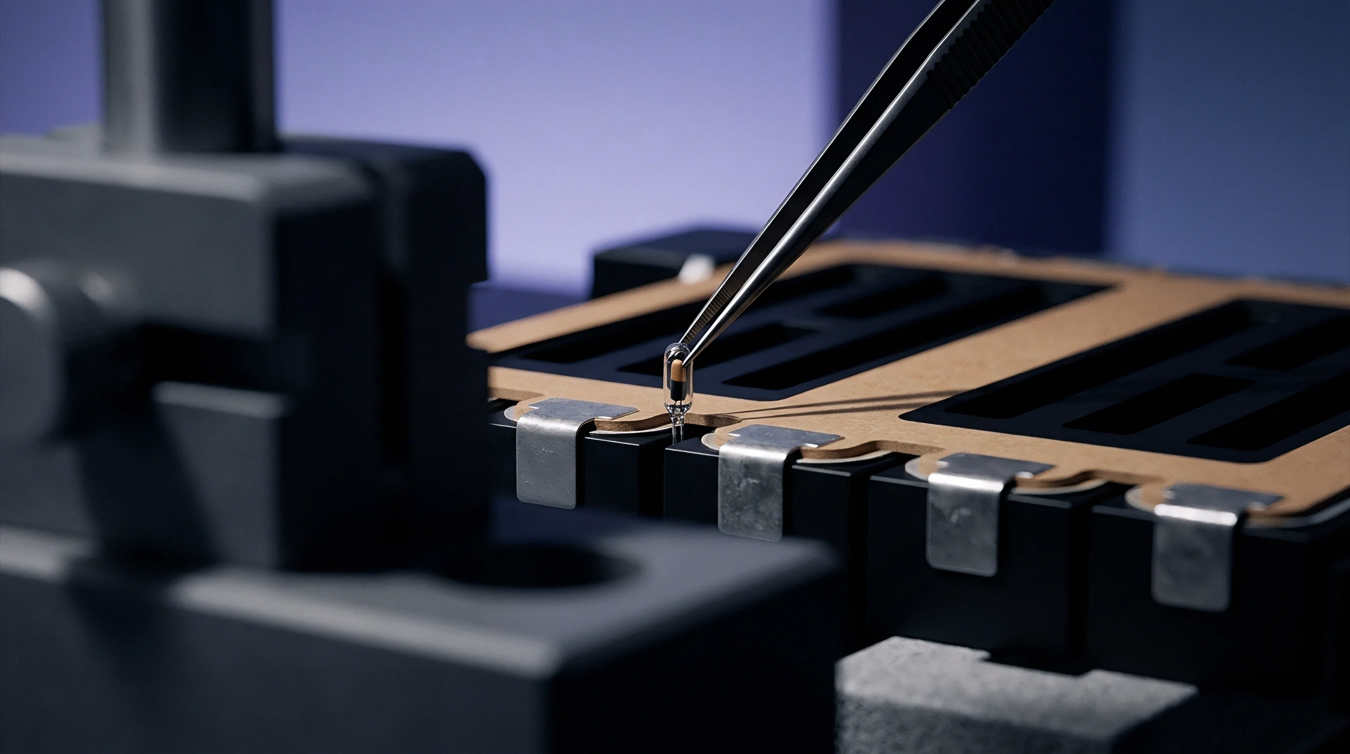
Commercial Warranty Allocation and Delivered Energy Economics
Enforcing warranty terms requires complete thermal and operational history logging. Non-volatile BMS memory tracks time spent at sub-zero temperatures alongside any current passed below allowable thermal limits. In warranty audits, service teams extract these telemetry logs to verify whether packs operated within contract boundaries.
Landed energy accounting must incorporate the power drawn by thermal management circuits in sub-zero environments. In cold climates, pre-heating cycles can consume up to 25 percent of total pack energy before vehicles move or stationary systems begin discharging. Modeling this thermal parasitic draw ensures operational cycle costs reflect field conditions and warranty reserves match actual exposure.