Tooling Investment Boundaries in Custom Prismatic Pack Development
Hard tooling for custom prismatic packs breaks even above 5,000 units, balancing extrusion die NRE against dynamic cell swelling and laser welding tolerances.

Die
Custom prismatic battery enclosures demand capital commitments across extrusion presses, stamping lines, and injection molds. Deciding when to transition from soft prototyping methods to hard tooling defines the financial baseline of a battery integration program. Upfront non-recurring engineering charges for custom pack tooling range from twenty thousand dollars for basic sheet-metal prototypes to over four hundred thousand dollars for high-speed, multi-cavity production tooling lines.

Capital Allocation across Tooling Phases
Early prototype builds rely on soft manufacturing pathways, including three-axis laser cutting, CNC machined end-plates, and manually formed busbars. Soft tooling provides short turnaround times for initial mechanical fit checks and low-volume pilot samples. Per-unit manufacturing costs remain prohibitively high during soft tooling phases because machining cycles take tens of minutes per module pan.
Structural tolerance bands on soft-tooled components reflect loose machining standards, introducing assembly stack-up variations that obscure early cell interface testing.
Tool steel wears progressively over extended production runs, changing part dimensions over time.
Transitioning to progressive stamping tools and custom aluminum extrusion profile dies drops unit enclosure costs sharply once production scales past one thousand packs annually. Hard tooling establishes fixed structural dimensions, high repeatability, and short cycle times required for automated assembly lines.
- Prototype soft tooling Soft tooling utilizes laser-cut aluminum sheet and CNC machined structural frames, avoiding major upfront capital expenditure during early verification steps.
- Progressive stamping dies Multi-stage carbide stamping tools produce nickel-plated copper busbars with consistent co-planarity, eliminating manual bending variance across high-volume production.
- Profile extrusion press tooling Custom steel extrusion dies shape side rails and bottom pans from 6005A-T6 aluminum alloy, establishing rigid perimeter walls for structural cell containment.
- Injection mold tooling Multi-cavity hardened steel molds form glass-filled PBT cell carrier trays, holding dimensional tolerances for inter-cell dielectric insulation.

Extrusion and Stamping Thresholds
Production volume dictates the physical transition from machined prototype components to dedicated high-speed forming tooling. Custom aluminum extrusion profile dies require press forces exceeding two thousand five hundred tonnes to force billet material through hardened tool steel apertures. Initial die trials for structural pack extrusions require multiple sizing correction iterations to eliminate section distortion, thermal contraction warping, and internal web wall thickness variation.
Aluminum extrusion dies for prismatic pack enclosures maintain a structural wall tolerance of plus or minus 0.15 millimetres under continuous pressing forces exceeding 2500 tonnes.
Progressive stamping dies for interconnect busbars process nickel-plated C1100 copper strips at high stroke speeds. Multi-station stamping dies execute blanking, piercing, bending, and coining within a continuous coil feeder setup. Tooling designers account for material springback and work hardening in half-hard copper grades to hold terminal hole locations within tight spatial limits.
Hard tooling investments scale rapidly as part geometries and multi-cavity requirements become more complex.
Committing to hard forming tools before freezing cell dimensions leads to catastrophic scrap charges, expensive mold modifications, and schedule slippages exceeding six months.

Tolerance
Prismatic lithium-ion cells change shape over operational lifetimes, expanding during daily charge cycles and swelling permanently as SEI layers thicken. Housing tooling must incorporate volumetric allowance for both reversible cyclic breathing and irreversible capacity-degradation expansion without compromising structural integrity or thermal path contact.

Mechanical Stack up and Expansion Allowances
Cell breathing during charge-discharge cycling creates dynamic dimensional shifts that housing designs absorb through calibrated compression elements. Commercial prismatic cells utilizing lithium iron phosphate or nickel manganese cobalt chemistries expand between 0.8 percent and 1.5 percent in thickness during initial formation cycles. Over three thousand operational cycles, cumulative solid electrolyte interphase growth drives irreversible cell thickness expansion up to 5.0 percent at eighty percent remaining capacity state of health.
Elastomeric pads take up this volumetric growth by compressing under load over the pack’s operational lifespan.
Inter-cell compression sheets made of microcellular polyurethane or silicone foam provide continuous mechanical restraint across cell face surfaces. Maintaining a minimum baseline preload pressure of 0.2 MPa prevents internal electrode delamination and suppresses localized lithium plating during high-rate charging. Tooling for rigid side frames must compensate for peak end-of-life pressure, which can reach 1.2 MPa when fully aged cells expand inside fixed pack volumes.
- Determine maximum end-of-life volumetric expansion of the selected prismatic cell from manufacturer life-cycle test data under 1C charge rates.
- Calculate total stack growth across all series-connected cell pockets by multiplying single-cell expansion by cell count per module.
- Select an elastomeric compression pad thickness that yields an initial mounting pressure between 0.2 MPa and 0.3 MPa at room temperature.
- Verify that compression pad deflection at maximum swelling keeps peak structural pressure below 1.2 MPa to prevent internal short circuits.
- Dimension the extruded side frame perimeter to contain the full compressed stack thickness under maximum operating temperatures.
Clamping pressure drifts across continuous temperature and charge cycling.
Accumulated dimensional variations across multiple stacked components can erode nominal clearance margins.

Enclosure Manufacturing Process Boundaries
Structural housing selection influences dimensional repeatability, heat extraction efficiency, and overall non-recurring engineering expenses. Extruded aluminum side rails combined with stamped bottom plates offer flexible length scaling for custom pack layouts without requiring complete mold redesigns. High-pressure die casting provides complete structural integration, forming thermal fluid channels, mounting lugs, and crash protection zones in a single tool pass, but demands high initial capital investment.
| Process Method | Initial Tooling NRE ($) | Dimensional Tolerance (mm) | Minimum Wall Thickness (mm) | Cycle Time per Shell (s) | Volume Break-Even (Units) |
|---|---|---|---|---|---|
| CNC Billet Machining | 5,000 | +/- 0.05 | 1.5 | 3,600 | 1 to 250 |
| Extruded Profile Assembly | 45,000 | +/- 0.15 | 2.0 | 180 | 251 to 5,000 |
| Aluminum High-Pressure Die Casting | 180,000 | +/- 0.25 | 2.5 | 45 | 5,001 to 50,000 |
| Stamped Sheet Metal Structure | 120,000 | +/- 0.30 | 1.2 | 25 | > 50,000 |
ISO 12405-4 compliance demands structural retention of prismatic cells at 50g shock loads, driving die-cast enclosure draft angles below 1.5 degrees.
A flexible side-plate extrusion design isolates cell swelling forces within replaceable tie-rods, whereas rigid die-cast cavity walls transfer internal expansion stresses directly into structural mounting points.

Contract
Commercial agreements in battery pack engineering establish who retains asset titles, who absorbs refurbishment expenses, and who signs compliance documents. Disagreements over tooling ownership arise when projects face early cancellation or volume shifts before initial non-recurring engineering outlays amortize fully across unit shipments.

Tooling Title and Intellectual Property Boundaries
Non-recurring engineering payments transfer physical ownership of forming dies to the purchasing entity when agreements contain explicit asset transfer provisions. Clear contract terms differentiate between proprietary manufacturing process IP held by the pack builder and product-specific tooling assets paid for by the customer. When buyers fund dedicated extrusion dies or injection mold inserts, contract language specifies serial number tagging, physical location tracking, and maintenance logs maintained by the contract manufacturer.
Contract provisions govern asset control and operational responsibilities across the full tooling lifecycle.
Full tooling buyouts grant the buyer absolute authority to relocate extrusion tools or injection molds to alternative manufacturing facilities if quality metrics fail. Partial tooling amortization models lower upfront capital exposure by embedding tool charges inside per-unit pack invoices, but leave tool ownership with the contract manufacturer until agreed minimum order quantities clear.
Soft tooling absorbs early design changes, while hard tooling punishes dimensional drift with full mold scrap costs.

How Do Tooling Commitments Shift across Production Tiers?
Tier-one cell integrators standardise terms that reassign tool refurbishment expenses once production volumes surpass five hundred thousand units. SPI Class 101 injection molds feature hardened tool steel cavities rated for one million molding cycles, whereas SPI Class 104 prototype tools use untreated aluminum frames that degrade after twenty-five thousand shots. Contract clauses specify tool wear thresholds, dimensional inspection cadences, and scrap allocation terms when tool degradation drives finished parts outside drawing tolerances.
Initial sample parts frequently uncover dimensional discrepancies during early qualification runs.
Incorporating an explicit asset bailment clause under UN 38.3 qualification transfer provisions forces the contract manufacturer to maintain and insure extrusion tooling at their expense until serial production terminates.

Fixture
Precision assembly of custom prismatic battery packs relies on specialized clamping systems, laser alignment rigs, and automated testing stations. Fixturing capital represents a substantial portion of overall factory bring-up expense, ensuring cell terminals line up perfectly with interconnecting busbars before joining operations begin.
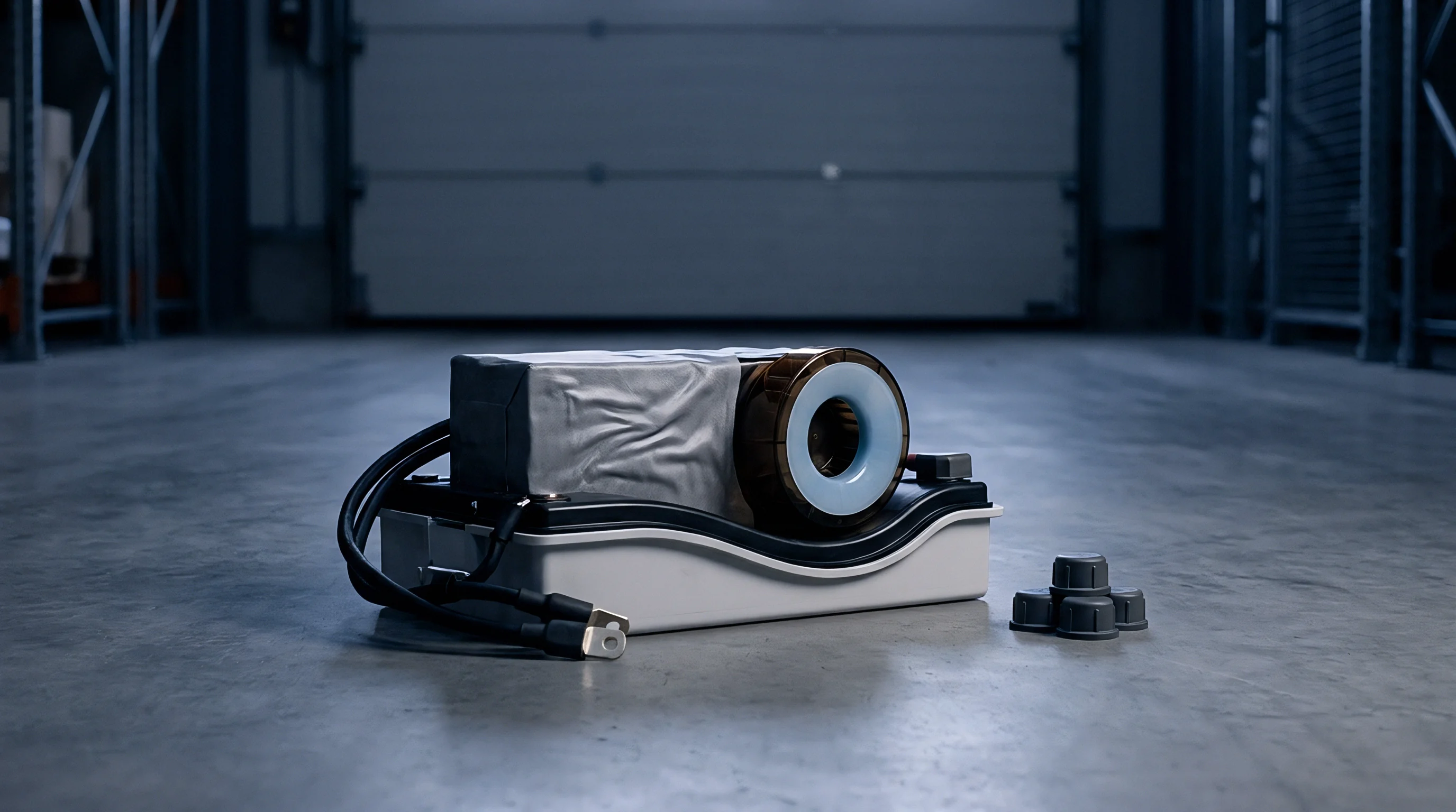
Laser Welding Precision and Fixturing Controls
Automated optical inspection units verify busbar alignment prior to high-power fiber laser joining operations on prismatic terminal surfaces. Joining copper-clad aluminum terminals requires precise mechanical clamping forces to close joint air gaps below 0.03 millimetres. Excessive clearance causes laser burn-through, internal spatter, and high contact resistance joints that exceed fifteen micro-ohms per connection point.
Uncontrolled gaps between joining surfaces ruin weld integrity and electrical conductivity.
Poor joint fit-up sharply increases scrap rates during high-speed automated welding runs.
Clamping fixtures incorporate high-rigidity pneumatic cylinders and ceramic touch points that isolate laser beam reflections while holding cell stacks under uniform physical restraint. Optical coherence tomography systems track keyhole depth dynamically during fiber laser pulses, halting beam emission if melt pool depth drifts beyond 0.8 millimetres into the cell cap assembly.
- Terminal co-planarity alignment Mechanical clamping plates force cell terminals into a uniform horizontal plane, keeping vertical stack variance under 0.05 millimetres.
- Pneumatic compression force controls Calibrated load cells continuously monitor side-wall pressure during pack binding, ensuring exact preload across cell stacks.
- Optical vision positioning sensors High-resolution vision systems guide laser welding optics to cell terminal centroids, preventing beam misplacement and insulation burn.
- Helium mass spectrometer chambers Sealed vacuum enclosure interfaces verify pack IP67 ingress protection and detects micro-cavity coolant loop leaks down to 10-6 mbar liters per second.

End of Line Test Interface Equipment
Electrical qualification equipment applies high-voltage isolation stresses and high-current discharge pulses to validate internal interconnect integrity. Fixturing interfaces must establish low-resistance contact with main power terminals without deforming nickel plating layers or damaging threaded terminal posts. Custom pogo-pin beds make contact with battery management system voltage sensing nodes, checking wiring harness continuity and cell balance circuit accuracy in a single automated step.
Repeated contact cycles accelerate physical wear on delicate test pins and contact interfaces.
Interconnect busbar stamping dies exhibit accelerated tool wear when processing nickel-plated copper alloys above half-hard temper.
Laser beam alignment failures stem from either incoming cell terminal height variation or clamping plate wear on the automated line.


Amortization
Financial modeling translates non-recurring capital outlays into unit-level cost impacts across defined production volume thresholds. Evaluating the total cost structure of custom prismatic pack tooling requires balancing upfront NRE outlays against unit assembly labor, scrap losses, and scheduled tool refurbishment cycles over the production lifecycle.

Unit Economics and Non Recurring Engineering Amortization
Spreading tool manufacturing costs across small production batches elevates individual pack costs beyond competitive market benchmarks. A worked evaluation demonstrates how tooling strategy governs final pack unit pricing. Consider a custom 100 kWh industrial battery pack enclosure built across four distinct volume scenarios.
Modifying enclosure designs alters internal heat transfer paths across different tooling configurations.
In Scenario A, a short pilot run of 500 units utilizes soft laser-cut components and CNC machined internal frames. Total NRE tooling capital remains low at $35,000, creating an amortized tooling cost of $70.00 per unit. High manual labor and lengthy CNC cycle times elevate component piece price to $2,400.00, yielding a total structural enclosure cost of $2,470.00 per pack.
In Scenario B, production reaches 2,500 units using semi-hard extrusion profiles and single-cavity injection molds. Upfront NRE increases to $120,000, which results in $48.00 per unit tooling amortization. Faster cycle times bring structural piece cost down to $950.00, reducing total structural pack cost to $998.00 per unit.
In Scenario C, production scales to 10,000 units backed by full hard production tooling, including progressive stamping dies and automated welding jigs. Upfront NRE capital totals $280,000, amortizing down to $28.00 per pack. High automation slashes piece part costs to $420.00, establishing a total structural enclosure cost of $448.00 per unit.
In Scenario D, high-volume production reaches 50,000 units using multi-cavity hardened steel tools and multi-axis robotics lines. Tooling NRE capital expands to $550,000, yielding a minimal amortized tool cost of $11.00 per unit. Enclosure component piece price drops to $260.00, delivering a total structural cost of $271.00 per unit.
Production yield drops quickly when dimensional variation forces components out of specification.

Landed Cost Sensitivity Analysis
Refurbishment cycles, scrap percentages, and import tariff classifications shift overall pack procurement costs during multi-year production runs. Tooling maintenance allowances typically run between five percent and eight percent of initial NRE per year, accounting for progressive die sharpening, ejector pin replacement, and laser welding optics cleaning.
| Production Volume Tier | Total Upfront Tooling NRE ($) | Tooling Amortization per Unit ($) | Structural Component Cost ($) | Yield Scrap Allocation ($) | Total Structural Unit Cost ($) |
|---|---|---|---|---|---|
| 500 Units (Pilot Soft Tooling) | 35,000 | 70.00 | 2,400.00 | 120.00 | 2,590.00 |
| 2,500 Units (Semi-Hard Tooling) | 120,000 | 48.00 | 950.00 | 28.50 | 1,026.50 |
| 10,000 Units (Hard Production Tooling) | 280,000 | 28.00 | 420.00 | 8.40 | 456.40 |
| 50,000 Units (Automated Hard Tooling) | 550,000 | 11.00 | 260.00 | 2.60 | 273.60 |
| Methodology Note | Figures reflect 6005A-T6 aluminum extrusion housing, C1100 copper busbars, and injection-molded PBT trays under 2024 industrial supply benchmarks. | ||||
Long-term production contracts require periodic re-evaluation of die wear metrics, ensuring that tooling maintenance costs stay aligned with projected pack assembly margins throughout the vehicle lifecycle.