Procurement Strategies for Custom Industrial Lithium Ion Battery Modules
Procuring custom industrial battery modules requires locking cell format trade-offs, welding verification, and compliance files before amortizing tooling.

Envelope
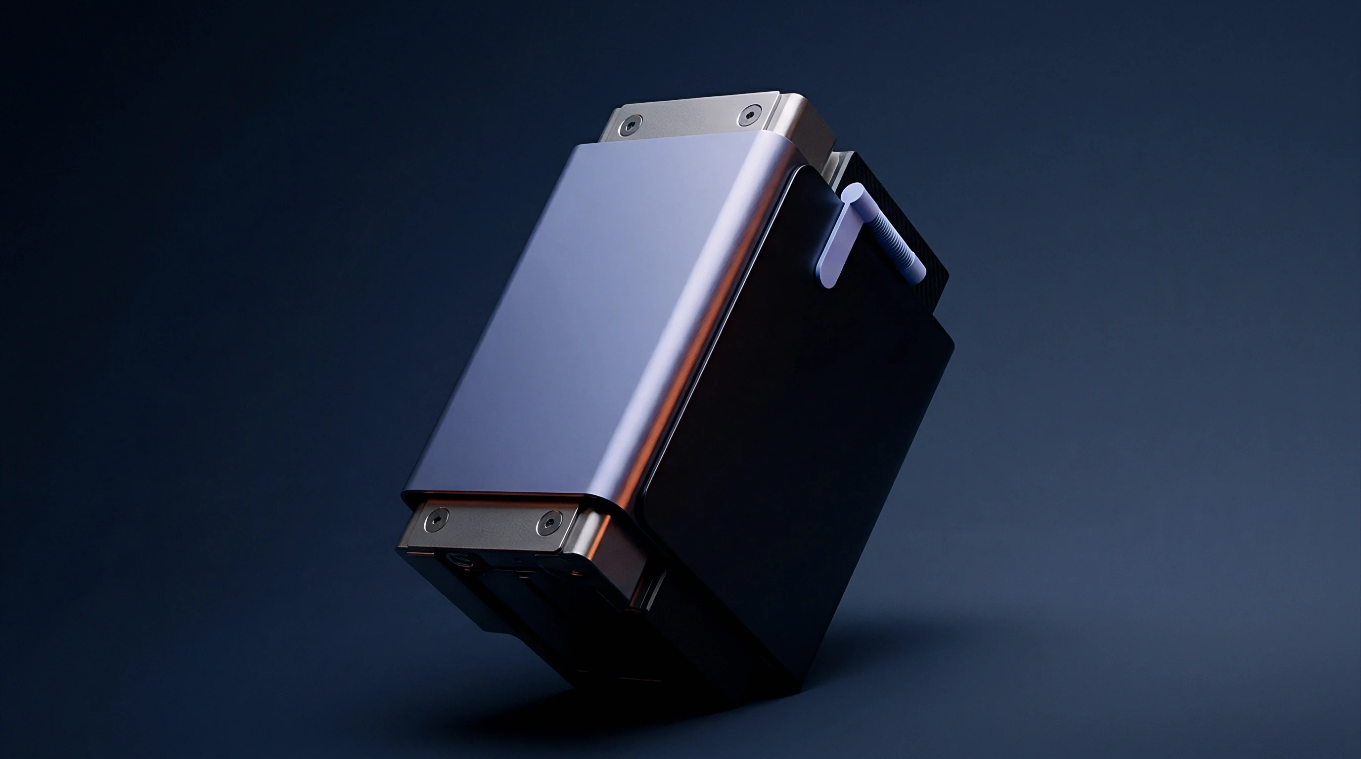
Form factor selection sets the thermal behaviour, enclosure housing, and mechanical restraint strategy for industrial power storage. Engineering teams weigh cylindrical, prismatic, and pouch architectures against shock limits, volumetric efficiency targets, and operating temperature profiles. Cylindrical 21700 or 4680 cells offer predictable physical containment using steel cans, internal pressure relief vents, and fixed cell spacing.
Because cylindrical layouts top out near sixty-eight percent volumetric efficiency inside rectangular enclosures, the remaining void spaces function either as dead air pockets or fluid channels. Equipment running under continuous 3G root-mean-square vibration from 10 Hz to 500 Hz depends on rigid axial compression and interstitial holders to keep tab welds from shearing.
Prismatic lithium iron phosphate (LFP) cells trade single-cell mass for structural efficiency. Stacking rectangular metal casings gets rid of empty interstitial spaces, raising module packing efficiency above eighty-two percent. Using large-format 50 Ah to 300 Ah prismatic units reduces total interconnects in the assembly, cutting potential contact failure points.
Electrochemical swell creates mechanical forces during cycling: LFP cell electrodes expand up to five percent by volume over two thousand deep discharge cycles, building steady pressure against module sidewalls. Structural end plates need an initial cold spring pressure between 0.3 MPa and 0.8 MPa to keep electrodes from delaminating while resisting peak end-of-life swell forces exceeding 3.0 MPa.
| Form Factor | Volumetric Efficiency | Required Stack Pressure | Thermal Transfer Path | Tooling Amortization Scope |
|---|---|---|---|---|
| Cylindrical (21700 / 4680) | 62% to 68% | None (Self-Contained) | Radial through outer steel wall | Low module tooling; high holder plastic injection tooling |
| Prismatic (LFP / NMC) | 78% to 85% | 0.3 MPa initial to 3.0 MPa end-of-life | Planar through bottom and large side faces | Moderate stamping tooling for structural end plates |
| Pouch (Laminated Foil) | 83% to 89% | 0.1 MPa to 0.5 MPa constant planar force | Planar through broad cooling plates | High compression frame and pouch pocket tray tooling |
Pouch cells deliver high gravimetric energy density by swapping hard metal cans for aluminum-laminated polymer film. Sealed foil perimeter seams remain vulnerable to electrolyte leaks if pinched during frame clamping. Applying uniform planar compression across the active cell area prevents localized lithium plating during high-rate charging in cold conditions.
Cooling pouch modules requires inserting metallic cold plates between cells, adding thermal interface layers that widen overall stack height tolerances. Manufacturing variations of plus or minus 0.15 mm per pouch cell accumulate across a twenty-cell series stack, creating a three-millimeter variance in final module length that compression springs must absorb.
Thermal limits drive cell chemistry choices in industrial operating environments. Nickel manganese cobalt oxide (NMC) formulations reach higher volumetric energy density, near 650 Wh/L at the cell level, but can enter thermal runaway at around 210 degrees Celsius. Lithium iron phosphate has a higher thermal runaway threshold above 270 degrees Celsius and releases far less energy during failure modes.
Heat rejection during continuous 2C discharge rates requires conduction paths capable of evacuating up to 15 watts per cell.
Achieving over eighty percent volumetric packing efficiency with large-format prismatic cells requires end plates designed to hold back three megapascals of end-of-life swell force.
Using the wrong cell format in high-vibration off-highway machinery leads to micro-fretting across terminal contact surfaces, breaking weld bonds and causing total open-circuit failures in the field.
Clamp
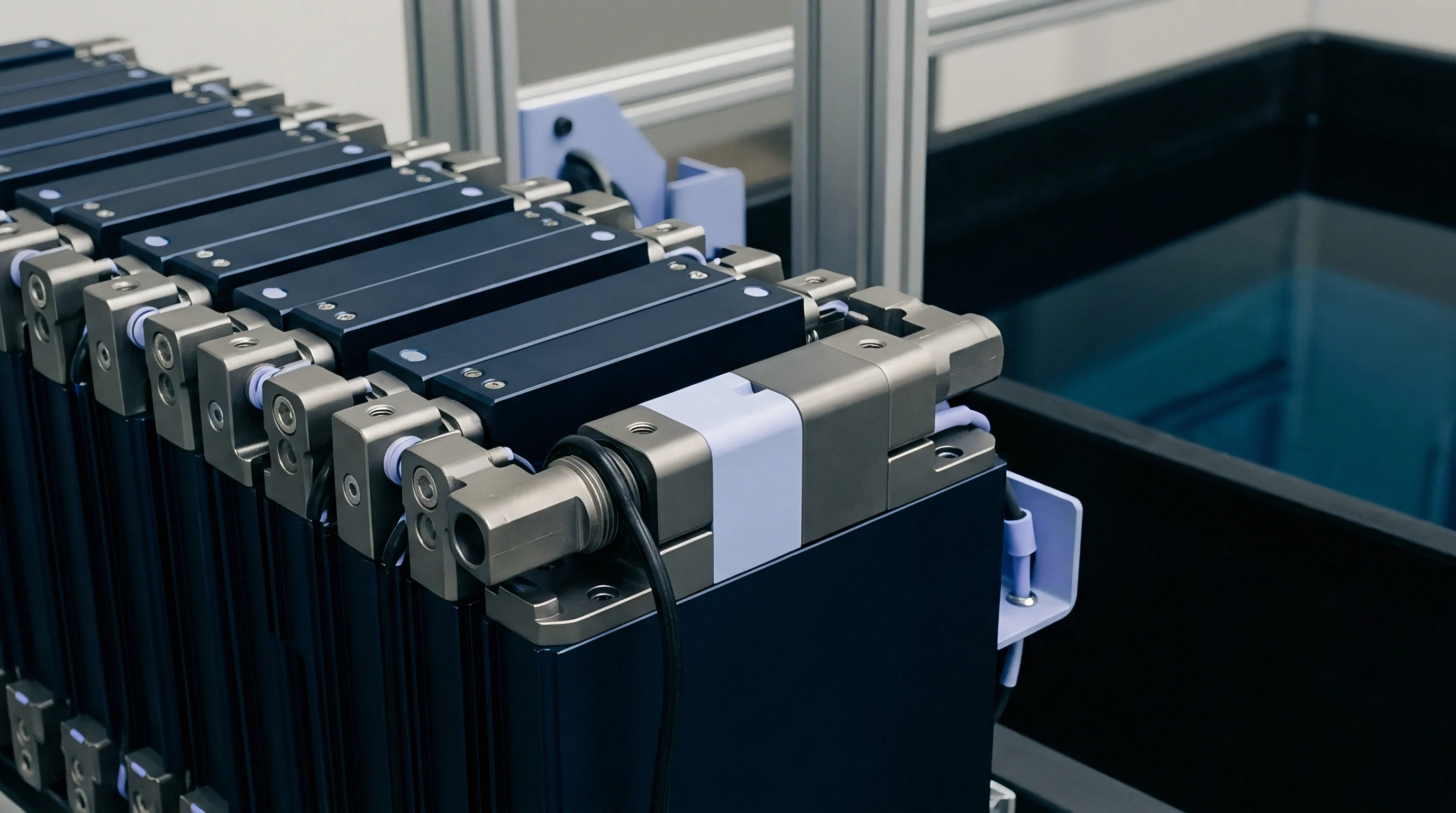
Interconnect layout and structural framing establish the physical durability of a finished pack. Joining cells into parallel and series configurations requires deciding between laser welding, ultrasonic wedge bonding, or bolted copper busbars. Continuous laser welding with 1070 nm fiber lasers achieves penetration depths between 0.8 mm and 1.5 mm in aluminum grade 1050 or nickel-plated copper current collectors.
Electrical contact resistance across a qualified laser weld stays below 15 micro-ohms. Fixtures must maintain spatial tolerances within plus or minus 0.05 mm to avoid blow-through holes that ruin cell seals or damage collector tabs.
Busbar sizing trades off electrical conductivity against thermal mass and mechanical flexibility. Solid copper busbars carry current densities up to 5 A per square millimeter without exceeding a 30 degrees Celsius temperature rise above ambient. Rigid electrical interconnects transfer mechanical stress directly into cell terminals during thermal expansion or frame deflection.
Laminated copper busbars made of thin interleaved copper foils absorb three-axis mechanical displacement, shielding internal cell terminal seals from shear forces. High-voltage modules operating above 400 volts direct current specify minimum clearance distances of 6.3 mm and creepage distances of 8.0 mm along insulation surfaces to comply with IEC 60664-1 isolation requirements under pollution degree two conditions.
Joint failures in custom welded modules stem from mechanical strain, thermal gradients, or surface contamination. Common degradation pathways include:
- Terminal post fatigue cracking driven by rigid busbar thermal expansion during heavy charge cycles.
- Intermetallic compound brittle fracture resulting from excessive heat input during copper-to-aluminum laser welding.
- Insulation sleeve dielectric breakdown caused by sharp stamped busbar edges puncturing protective films.
- Galvanic corrosion at contact faces where raw aluminum meets unplated copper in humid operating environments.
Qualifying welded busbar interconnects on the production line involves a sequence of destructive and non-destructive tests on pilot units.
- Measure baseline resistance across every busbar joint using a four-wire Kelvin milliohm meter at room temperature.
- Check weld pool depth and cross-sectional fusion area using optical coherence tomography or ultrasonic micro-imaging.
- Expose five sample modules to continuous random vibration profiles per UN 38.3 Test 3 across all three orthogonal axes.
- Re-measure contact resistance at every weld joint to check for internal micro-fissures or structural loosening.
- Run destructive peel tests on sampled terminals, requiring parent material tear-out rather than weld interface separation.
| Joining Method | Material Pair | Mean Resistance | Minimum Shear Strength | Process Thermal Impact |
|---|---|---|---|---|
| Fiber Laser Welding | Nickel-Plated Copper to Nickel | 8 to 12 micro-ohms | 450 N per joint | Localized micro-second pulse heat |
| Ultrasonic Bonding | Aluminum 1050 to Aluminum 1050 | 10 to 15 micro-ohms | 320 N per wire stitch | Zero thermal heat-affected zone |
| Threaded Fastener (M6) | Tin-Plated Copper to Brass Terminal | 25 to 40 micro-ohms | 9.0 Nm torque rating | No thermal heat input |
Thermal interface materials (TIM) bridge the gap between individual cell bases and the module outer cold plate. Dispensing silicone-free gap fillers with thermal conductivities between 2.5 W/m K and 6.0 W/m K eliminates micro air gaps, lowering interfacial thermal resistance below 0.5 degrees Celsius square centimeters per watt. Dispense volume control prevents excess material from squeezing into high-voltage clearance voids.
Cell monitoring circuits printed on flexible polyimide circuits (FPC) replace bulky discrete wire harnesses for cell voltage and thermistor sensing. Voltage tap traces carry current-limiting surface-mount fuses rated at 0.5 amperes directly at the terminal attachment point, isolating sensor line short circuits before trace melting occurs.
Flexible polyimide sensing circuits with fused terminals prevent wire harness short circuits while absorbing dimensional stack changes during thermal cycling.
Microscopic cell terminal oxide layers can cause unexpected contact resistance spikes while remaining within normal industrial production tolerances.
Proper creepage clearance gaps prevent high-voltage electrical arcing across module components.
Batch
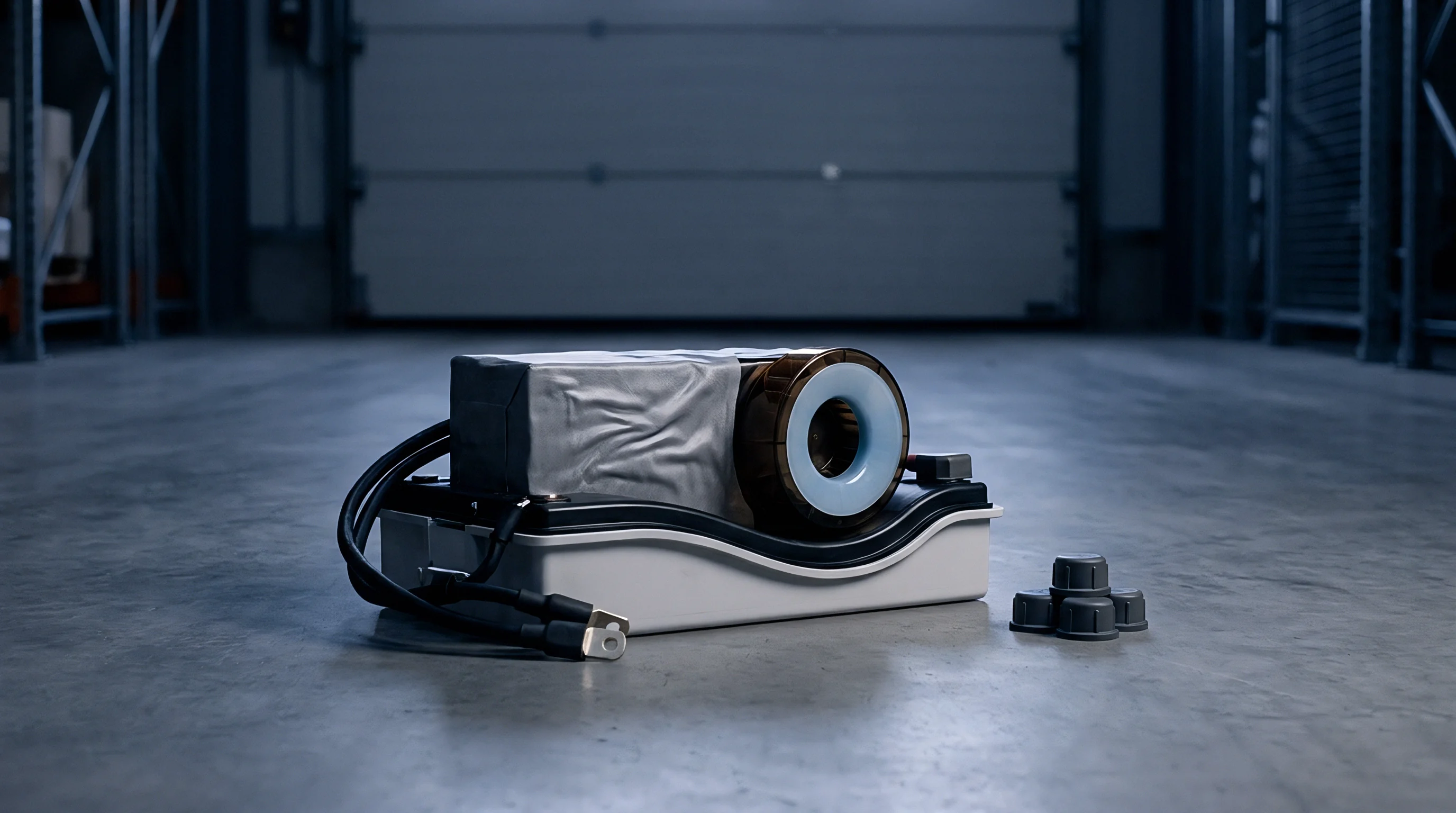
Cell uniformity governs the overall operating lifespan of a multi-cell industrial module. Commercial manufacturing lines introduce minor variations in active material coating weight, separator thickness, and electrolyte fill volume. Unscreened cell lots show internal impedance spreads wider than twelve percent and capacity spreads exceeding three percent.
When connected in series strings, the weakest cell reaches its lower voltage cutoff limit first during discharge, terminating pack output while higher-capacity cells retain unused energy. During charging, low-capacity cells reach upper voltage limits prematurely, triggering management system cutoffs and accelerating localized degradation.
Capacity grading and self-discharge screening weed out statistical outliers before module integration. Sorting cells into tight performance bands balances series strings. High-precision testing equipment measures open-circuit voltage drift over a fourteen-day room-temperature dwell period to derive the cell K-value in millivolts per day.
Standard commercial cells exhibit K-values between 0.05 mV/day and 0.20 mV/day, whereas cells containing microscopic metallic contaminants or separator pinholes show self-discharge rates exceeding 0.50 mV/day. Tracking self-discharge over time catches internal micro-shorts before assembly.
Electrochemical impedance spectroscopy (EIS) measures real and imaginary impedance components across frequency sweeps from 10 kHz down to 10 mHz. The real axis intercept at 1 kHz identifies the pure ohmic resistance from the current collector and electrolyte bulk. Charge transfer resistance appears as a semicircular arc in the mid-frequency spectrum, revealing electrode reaction kinetics.
Industrial module procurement agreements define incoming cell grading bins based on dual criteria: capacity windows within plus or minus 1.0 percent of target nominal values, and 1 kHz AC resistance windows within plus or minus 2.5 percent.
The impact of cell grading shows clearly when modeling module lifetime yield under standard versus tightened parameters. Consider an order of 10,000 cells intended for assembly into 100 series-connected modules of 100 cells each. Assume an unsorted cell population following a normal distribution with a standard deviation of capacity equal to 1.5 percent of nominal rating.
Under baseline loose sorting (plus or minus 3.0 percent capacity binning), statistical modeling projects that ninety-two percent of constructed series strings will contain at least one cell sitting at the lower three-sigma bound. This lower-bound cell reduces effective module usable capacity by 4.5 percent from day one, accelerating capacity fade and dropping cycle life from 3,500 cycles down to 2,200 cycles to eighty percent state-of-health.
Tightening the screening window to plus or minus 0.75 percent capacity binning increases initial cell factory reject rates from 0.3 percent to 4.2 percent. The rejected cells are returned to the supplier or repurposed for low-rate stationary storage. The resulting modules assembled from tightly binned cells maintain string capacity balance within 1.2 percent across their operational lifespan.
The yield loss expense during cell sorting adds approximately 3.8 percent to raw cell procurement cost, but extends field operational lifespan by 59 percent, lowering total amortized energy cost per delivered kilowatt-hour over the equipment operating lifetime.
Purchasers evaluate incoming cell shipments using structured ANSI/ASQ Z1.4 sampling plans to verify defect thresholds without testing whole production lots. The qualification framework evaluates incoming lots through systematic criteria:
- Acceptable Quality Level thresholds fixed at 0.065 percent for critical safety defects including internal short circuits and zero-voltage cells.
- Major defect limits set at 0.40 percent for physical dimensions out of tolerance, damaged tab seals, or incorrect terminal polarity markings.
- Minor defect limits set at 1.50 percent for cosmetic pouch wrinkles, surface paint discoloration, or missing barcode labels.
- K-value dwell verification requiring sample cells to be re-tested after a secondary 72-hour elevated temperature storage protocol at 45 degrees Celsius.
A capacity grading window restricted to plus or minus three-quarters of one percent increases initial cell screening rejection rates while expanding module field cycle life by over fifty percent.
Mixing cells from different production manufacturing dates within a single series string leads to early module failure because internal impedance grows at uneven rates.

Dossier
Regulatory certification records establish the legal clearance to ship, assemble, and commercialize custom battery equipment. International dangerous goods regulations classify lithium-ion modules as Class 9 hazardous materials under UN 3480 or UN 3481 designations. Achieving transport authorization requires passing the UN Manual of Tests and Criteria Section 38.3 protocol.
The testing suite applies eight distinct stress tests sequentially or in parallel: altitude simulation (T1), thermal shock cycling from -40 to +72 degrees Celsius (T2), vibration (T3), mechanical shock up to 150G (T4), external short circuit at 55 degrees Celsius (T5), impact or crush (T6), overcharge (T7), and forced discharge (T8). Modifying a certified module frame or changing an internal cell supplier voids existing UN 38.3 test summary reports, requiring complete re-qualification.
Industrial product safety standards mandate hardware and software architecture evaluations. IEC 62133-2 governs safety requirements for portable sealed secondary cells and modules in industrial applications, focusing on thermal abuse, mechanical drop, and internal short-circuit resistance. Stationary and heavy industrial storage equipment falls under UL 1973, which demands structural enclosure integrity, fire propagation containment, and functional safety verification of the battery management system.
Under UL 1973, single-cell thermal runaway testing proves that an internal propagation event within one module cell will not trigger cascading thermal runaway into adjacent cells.
Regulatory mandates extend into material traceability and environmental impact reporting. The European Union Battery Regulation (2023/1542) requires comprehensive supply chain documentation, including carbon footprint declarations and digital battery passports for industrial storage systems exceeding 2 kWh capacity. Procurement contracts must mandate vendor compliance with material reporting standards, specifying recycled cobalt, lithium, nickel, and lead ratios.
Valid transport certification remains mandatory prior to shipping.
A complete custom module compliance dossier contains standardized technical documents:
- UN 38.3 Test Summary Report signed by an accredited third-party test laboratory, detailing sample quantities and mass loss percentages.
- Material Safety Data Sheets (MSDS) detailing chemical composition percentages, toxicological data, and emergency response procedures per GHS guidelines.
- Declaration of Conformity proving alignment with low-voltage directives, electromagnetic compatibility requirements, and RoHS/REACH substance limits.
- BMS Functional Safety Assessment Record validating ISO 26262 ASIL or IEC 61508 SIL level compliance for safety-critical hardware cutoffs.
International transport regulations mandate complete re-testing under UN 38.3 standards whenever a structural module frame modification or cell supplier change occurs.
Standard purchase agreement terms stipulate that the cell supplier retains full legal liability for factory-level cell manufacturing defects, whereas the module integrator assumes liability for interconnect fatigue failures, BMS firmware errors, and mechanical frame insulation breaches.
Standard commercial clauses mandate that the module integrator holds full indemnification responsibility for third-party damages if field thermal runaway incidents trace back to uncertified BMS firmware changes executed after initial UN 38.3 file sign-off.
Outlay
Non-recurring engineering fees, custom fixture costs, and landed logistics expenses dictate the true unit economics of tailored energy storage. Initial non-recurring engineering (NRE) charges cover custom plastic injection molds for cell holders, progressive stamping dies for aluminum busbars, extruded aluminum enclosure tooling, and specialized automated welding fixtures. Tooling NRE charges for a custom industrial module typically range from 45,000 USD for basic cylindrical pack structures to over 250,000 USD for IP67-sealed die-cast prismatic modules.
Amortizing these fixed costs across low production volumes drastically inflates effective unit prices.
Minimum order quantities (MOQ) established by tier-one cell manufacturers force procurement teams to balance inventory carrying costs against baseline cell unit prices. Primary cell producers enforce minimum shipment volumes ranging from 50,000 to 200,000 cells per order batch. Secondary integrators and pack assemblers bridge this gap by aggregating demand, though they add margin markups between eight and eighteen percent.
Scrap allocation parameters must be calculated directly into financial quotes. Assembly yield loss across cell sorting, laser welding, module enclosure potting, and end-of-line testing averages between 1.5 percent and 3.5 percent on mature lines, and up to 8.0 percent during NPI ramp phases.
| Cost Component | Low Volume (500 Units) | Medium Volume (5,000 Units) | High Volume (50,000 Units) |
|---|---|---|---|
| Raw Cell Sourcing Cost | $120.00 / kWh | $98.00 / kWh | $82.00 / kWh |
| Module BMS Hardware | $35.00 / kWh | $22.00 / kWh | $14.00 / kWh |
| Structural Components & TIM | $28.00 / kWh | $16.00 / kWh | $9.50 / kWh |
| Amortized Tooling NRE | $40.00 / kWh ($200k NRE) | $4.00 / kWh ($200k NRE) | $0.40 / kWh ($200k NRE) |
| Hazardous Freight & Tariffs | $18.50 / kWh | $12.00 / kWh | $8.20 / kWh |
| Total Landed Module Price | $241.50 / kWh | $152.00 / kWh | $114.10 / kWh |
Landed cost calculations incorporate complex international shipping surcharges, customs duties, and dangerous goods transport insurance. Class 9 hazardous goods freight carries specialized ocean container packing requirements, certified dangerous goods declarations, and port handling surcharges that increase baseline sea freight rates by thirty to fifty percent compared to standard cargo. Import tariffs on lithium-ion cells and battery modules vary substantially based on country of origin, with specific section tariffs adding up to 25 percent duty surcharges on finished modules.
Warranty reserve accruals complete the financial model for custom module procurement. Field failure rates for industrial battery modules operating under demanding thermal and vibration environments average between 0.2 percent and 0.8 percent over a five-year warranty period. Calculating warranty reserve funds requires accounting for full module replacement cost, double-leg hazardous transport logistics, onsite technician labor rates, and scrap processing fees for damaged power units.
Structuring purchase contracts with dual-source cell qualifications protects manufacturing timelines against single-factory supply disruptions while retaining leverage during annual price adjustment negotiations.