Thermal Interface Material Compression Decay in Battery Pack Design
Thermal interface material compression decay causes loss of contact pressure, increasing thermal resistance and accelerating cell aging over battery pack operational life.


Contact

Surface Micro-Asperities and Thermal Contact Resistance
Heat dissipation across cell-to-chassis interfaces depends directly on continuous physical conformity between solid surfaces. Microscopic surface roughness on extruded aluminum cold plates and prismatic cell casings creates air gaps where surface peaks meet. Air at atmospheric pressure exhibits a thermal conductivity near 0.026 W/m·K, acting as a potent barrier to conductive thermal transport.
Applying a thermal interface material displaces air pockets, establishing a liquid or elastomeric bridge across the joint.
Initial mechanical compression forces the material into surface asperities. Lower viscosity gap fillers and compliant elastomeric pads require specific clamping pressures to reach minimal thermal contact resistance. Increasing assembly force compresses the bulk material, reducing bond line thickness while expanding the true microscopic contact area.
Thermal resistance decreases exponentially up to a threshold pressure, beyond which further compression yields diminishing thermal returns while elevating mechanical stress on cell enclosures.
| Material Format | Chemistry Type | Bulk Conductivity (W/m·K) | Nominal Assembly Strain (%) | Initial Contact Stress (kPa) |
|---|---|---|---|---|
| Two-part Liquid Gap Filler | Addition-cure Silicone | 1.5 – 3.5 | 15 – 30 | 50 – 150 |
| Cured Elastomeric Pad | Filled Polyurethane | 2.0 – 6.0 | 20 – 40 | 150 – 400 |
| Non-silicone Dispensed Gel | Polyolefin / Acrylic | 1.2 – 2.8 | 10 – 25 | 30 – 100 |
| Phase Change Film | Paraffin Wax Blend | 3.0 – 8.0 | 5 – 15 | 100 – 300 |
Compressive force across the pack cooling interface alters bulk thermal conductivity. Heavily filled elastomeric systems rely on dense networks of aluminum oxide or boron nitride particles suspended within a polymer backbone. Excessive initial squeeze forces liquid resin out of high-pressure zones, changing local particle packing density and altering thermal pathways.
Interfacial impedance dominates heat flow when bond lines drop below 0.10 mm. Thinner bond lines reduce conductive distance, yet surface preparation tolerances set physical limits on minimum thickness. Machining marks on cold plates, dimensional tolerances across prismatic cell bottoms, and assembly alignment skew create spatial variations in compression force across a single module footprint.
Module designers set assembly preload values by calculating the mechanical strength of module endplates, bottom plates, and cell casing walls. Exceeding yield limits risks permanent casing deformation, internal short circuits, or pouch seal failure. Lower initial compression pressures safeguard fragile cell housings while accepting higher initial thermal resistance.
Assembly lines achieve consistent interfacial contact by balancing mechanical tolerances with gel rheology.
Creep
Viscoelastic Relaxation Mechanics under Constant Strain
Polymer matrices in thermal interface materials exhibit time-dependent viscoelastic decay when held under constant mechanical strain. Initial assembly applies fixed deflection to gap pads or cured dispensed gels, creating an immediate peak compressive stress. Over time, polymer chains reorient and slip at the molecular level, relieving internal stress without changing the physical distance between the cold plate and the cell casing.
Initial assembly clamping stress in filled silicone gap pads drops by thirty to fifty percent within forty-eight hours of installation at ambient temperature.
Temperature accelerates viscoelastic relaxation rate following Arrhenius dynamics. Operating module temperatures reaching 45 degrees Celsius speed up polymer chain mobility, shortening the timeframe required for stress decay. Higher thermal environments cause cross-linked networks to relax toward residual equilibrium stress levels far lower than short-term laboratory datasheets indicate.
Compression set measures permanent material deformation following strain release. High compression set values signify that a material loses elasticity, failing to exert outward force against moving substrate interfaces. Polyurethane matrices often demonstrate lower initial compression set than ambient-cured silicone formulations, yet exhibit higher moisture sensitivity over operational lifespans.
- Primary Stress Decay Phase ~ Rapid molecular chain realignment occurs within hours of compression, reducing initial assembly force by up to half at room temperature.
- Secondary Creep Phase ~ Extended logarithmic decay continues across thousands of operating hours, driven by ambient thermal cycling and steady background mechanical strain.
- Equilibrium Plateau Phase ~ Retained mechanical stress stabilizes at a residual baseline, where polymer cross-links resist further structural reorientation under static gap conditions.
Constant displacement control in battery pack structures differs fundamentally from constant load control. Enclosure bolts and module retaining brackets fix the geometry, forcing the thermal interface material to operate in stress relaxation mode. As internal stress declines, interfacial contact pressure drops, rendering the interface vulnerable to gap separation during shock and vibration events.
Neglecting long-term viscoelastic relaxation leads to interface lift-off, elevated cell operating temperatures, and accelerated battery capacity degradation during extended field service.
Stack
Dynamic Cell Expansion and Tolerance Stack-Up Interactions
Lithium-ion cells undergo thickness variations during daily charge-discharge cycling and over multi-year life. Anodes expand during lithiation, creating cyclic mechanical breathing that compresses the interface material against rigid structural frame members. Pouch and prismatic formats show thickness growth up to eight percent over thousands of full-equivalent cycles due to solid electrolyte interphase accumulation and gas generation.
Accumulated dimensional tolerances across multi-cell modules alter local gap dimensions. A module stack consisting of twelve prismatic cells exhibits cumulative casing tolerance variations reaching plus or minus 1.2 mm. Fastener torque tolerances, thermal plate flatness specs, and module frame stiffness variations compound gap uncertainty at individual cell cooling surfaces.
Consider a module design housing a prismatic cell stack above an integrated liquid cooling plate. Mechanical stack-up analysis defines a nominal gap thickness of 1.50 mm, with a worst-case tolerance envelope ranging from 0.80 mm to 2.20 mm. Installing a 2.00 mm nominal elastomeric gap pad into this assembly produces variable local strain and stress profiles across the pack base.
At minimum gap condition (0.80 mm), the pad experiences 60 percent strain. Initial local compression stress reaches 450 kPa, risking cell wall indentation. At maximum gap condition (2.20 mm), nominal compression strain falls to zero, leaving a 0.20 mm clearance gap that completely halts direct conductive heat transfer.
Designing for maximum gap coverage forces extreme over-compression in minimum gap zones.
- Minimum Mechanical Gap ~ Maximum material strain creates high peak stress, accelerating filler migration, matrix tearing, and physical cell housing deformation.
- Nominal Mechanical Gap ~ Optimal material strain balances low thermal contact resistance with acceptable mechanical stress on adjacent cell structures.
- Maximum Mechanical Gap ~ Inadequate strain results in poor surface wetting, residual air pockets, high interface impedance, and localized thermal hot spots.
Dynamic cell breathing modifies long-term stress decay trajectories. Repeated cyclic compression pumps liquid matrices outward from central cell regions toward open module edges. Thinning thermal pad zones under cell centerlines experience severe stress relaxation during discharge phases when cells contract, creating transient air voids.
Suppliers frequently defend field thermal degradation by claiming that module gap dimensions expanded beyond the maximum strain limit specified in baseline material engineering drawings.
Drift
Can Liquid Gap Fillers Outperform Cured Elastomeric Pads over Multi-Year Thermal Cycling?
Liquid gap fillers and pre-cured elastomeric pads exhibit distinct degradation modes over long-term pack operation. Dispensed two-component liquid systems form custom-shaped interfaces that match surface profiles without high assembly forces. However, incomplete volumetric mixing, ratio drift in automated dispensing heads, or low ambient cure temperatures alter polymer cross-linking density, accelerating compression decay and physical breakdown.
Thermal pumping acts as a primary mechanical driver of interface drift. Alternate heating and cooling cycles induce differential thermal expansion between aluminum cold plates and cell casings. Aluminum expands at approximately 23 microstrain per degree Celsius, while cell casings and composite housings expand at different rates.
Relative lateral displacement shears the interface layer, forcing uncrosslinked fluid constituents out of the joint.
ISO 16750-3 mechanical shock and vibration exposure degrades under-compressed gap pads, causing interfacial slip and localized thermal impedance spikes.
Silicone-based formulations suffer from low molecular weight siloxane fluid bleeding. Unreacted silicone oils migrate out of the filler matrix under combined pressure and heat, creeping along metal surfaces. Fluid loss hardens the bulk material, reducing compliance and increasing hardness from 30 Shore OO to over 75 Shore OO.
Hardened matrices lose ability to track dynamic cell movement during thermal cycling.
| Failure Mechanism | Physical Root Cause | Thermal Consequence | Mechanical Consequence |
|---|---|---|---|
| Thermal Pump-Out | Differential CTE lateral shear during thermal cycling | Thinning at center, localized thermal hot spots | Material accumulation at module edges |
| Silicone Oil Bleeding | Fluid phase separation under continuous pressure | Dry-out, loss of surface wet-out capability | Matrix embrittlement, elevated hardness |
| Delamination | Viscoelastic relaxation combined with gap enlargement | Air gap formation, complete thermal disconnect | Zero interfacial compressive stress retention |
| Cohesive Cracking | Cyclic mechanical strain exceeding material fatigue limit | Disrupted bulk conductive pathways | Fragment breakdown, particulate migration |
Non-silicone chemistry platforms eliminate siloxane contamination risks in sensitive electrical zones. Polyurethane and polyolefin gels maintain adhesion without oil bleeding, yet exhibit lower continuous thermal stability ratings. Exposure to temperatures above 80 degrees Celsius over extended periods causes matrix oxidation, chain scission, and permanent volumetric shrinkage.
Air void formation at cell-to-pad interfaces increases localized thermal resistance by orders of magnitude. A 0.05 mm air gap introduces a thermal resistance equivalent to several millimeters of bulk interface material, elevating peak cell operating temperatures during fast-charging events.
Does long-term structural settling inside high-vibration commercial vehicles destroy interfacial thermal continuity before cells reach end-of-life capacity limits?
Probe
ASTM E1530 and Stress Relaxation Testing Standards
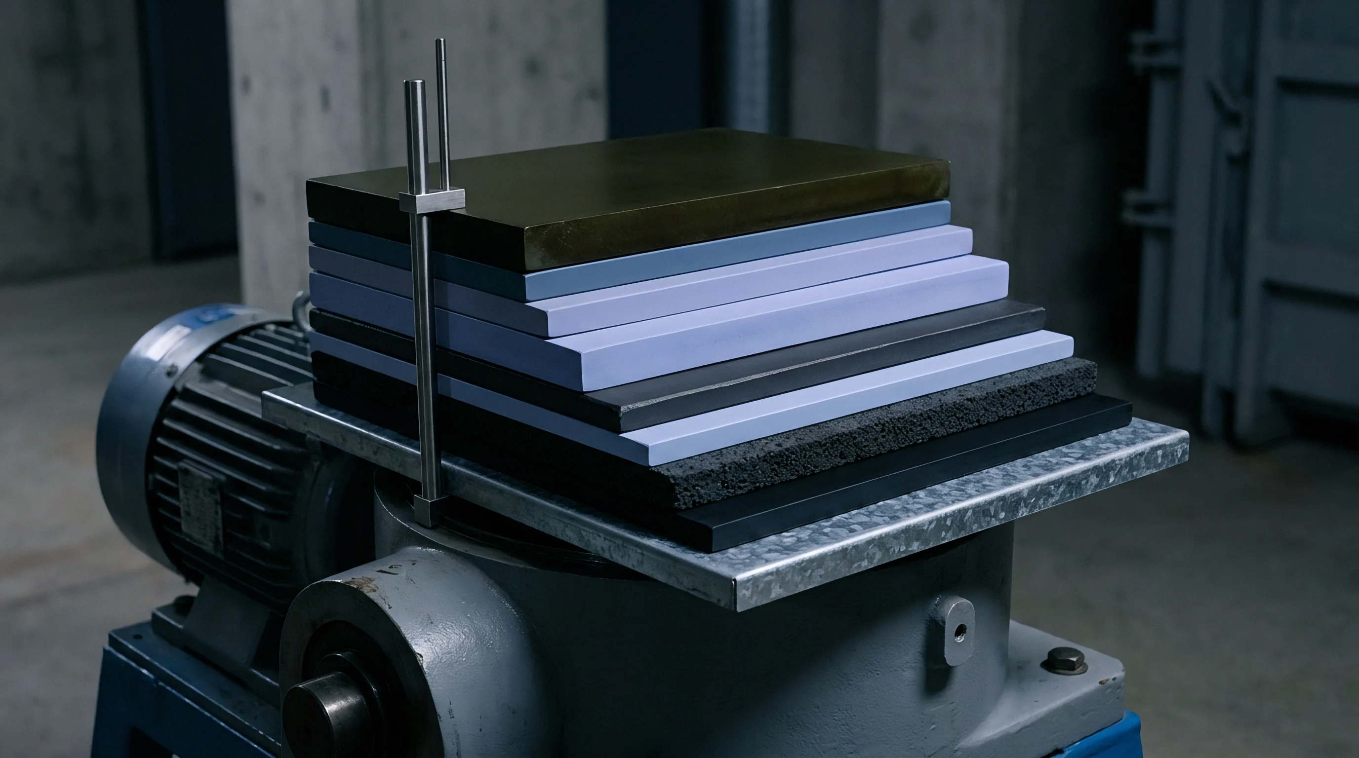
Verifying compression decay rates requires standard test protocols that isolate mechanical relaxation from thermal aging. ASTM E1530 measures thermal impedance across compressed specimens under controlled mechanical loads. Testing materials under constant displacement rather than constant load reproduces actual pack assembly physics, tracking interfacial stress decay against time and temperature.
Characterizing long-term mechanical relaxation require testing specimens across full thermal operating envelopes rather than single ambient room conditions.
Rheological characterization using dynamic mechanical analysis evaluates material storage modulus, loss modulus, and complex viscosity across temperature sweeps. Rising storage modulus indicates cross-linking degradation or dry-out, while falling loss modulus correlates with loss of dampening and surface conformity. Accelerated thermal aging trials subject compressed samples to continuous 85 degrees Celsius and 85 percent relative humidity conditions for 1,000 hours.
Standard compression set procedures follow ASTM D395 Method B, which fixes specimen deflection at 25 percent for specified durations. Test metrics calculate unrecovered deflection following sample release. Relying solely on ASTM D395 values understates field compression decay because the test measures unconstrained recovery rather than residual force retention under continuous constraint.
- Mount fresh material specimens between temperature-controlled platen surfaces fitted with high-precision load cells and micrometer positioners.
- Compress specimens to predetermined gap thicknesses matching maximum, nominal, and minimum stack-up design limits.
- Expose test fixtures to thermal cycling profiles from minus 40 degrees Celsius to 85 degrees Celsius for a minimum of 500 complete cycles.
- Log continuous compressive force decay and calculate instantaneous thermal resistance using steady-state heat flux sensors.
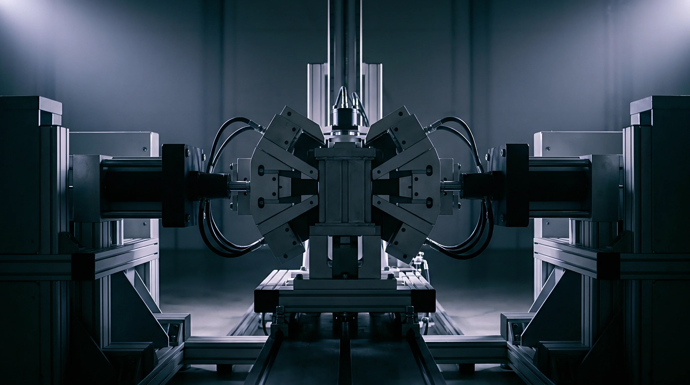
Advanced structural testing incorporates simultaneous mechanical vibration during thermal conditioning. Tri-axial electrodynamic shakers apply random vibration profiles per UN 38.3 transport standards while thermal plates maintain peak operating temperatures. Combined mechanical and thermal stress accelerates filler settlement and bond line thinning.
Commercial purchase contracts stipulate compliance with ISO 22821 protocols, defining minimum residual compressive stress requirements after standardized aging regimes.

Margin
Thermal Interface Safety Margins and Enclosure Fastener Torque Retention
Engineering robust battery packs requires integrating long-term compression decay allowances into thermal stack-up calculations. Designers apply derating factors to initial material thermal performance, assuming a 30 to 50 percent loss in compressive contact stress over operational vehicle lifespans. Worst-case thermal modeling relies on aged thermal contact resistance values rather than fresh supplier datasheet metrics.
Field thermal performance matches early design models only when residual interface stress remains positive across all thermal expansion extremes.
Structural module designs incorporate spring elements or compliant mechanical stops to maintain baseline compression. Wave springs, Belleville washers, or engineered foam backing layers absorb cell thickness growth while preserving continuous outward pressure on thermal interface layers. External mechanical compliance reduces stress spikes during cell charging while preventing complete force drop-off during cell discharge.
| Design Parameter | Conservatively Rated Target | Aggressive Target | Failure Threshold |
|---|---|---|---|
| Minimum Residual Stress | 50 kPa | 20 kPa | < 5 kPa |
| Maximum Compression Set | < 15% (after 1000h at 85°C) | < 30% (after 1000h at 85°C) | > 50% |
| Designed Bond Line Allowance | Nominal + 0.50 mm design gap | Nominal + 0.20 mm design gap | Zero clearance tolerance |
| Torque Decay Safety Factor | 1.3x initial fastener clamp force | 1.1x initial fastener clamp force | 1.0x (un-derated) |
Enclosure fastening strategies impact long-term joint integrity. Decay in gap pad spring force reduces thread friction on module compression tie-rods and bottom-plate mounting bolts. Unsecured threaded fasteners back out under chassis vibration when internal joint preload falls below threshold limits, leading to catastrophic enclosure loosening and structural isolation failure.
Mechanical layout choices determine where compliance responsibility sits within the pack architecture. Cell-level compressible shims absorb manufacturing variations and pouch cell swelling, allowing the main structural thermal interface material to operate within a narrow strain band. Isolating cell expansion mechanics from the thermal interface layer stabilizes thermal resistance across multi-year operating windows.
Selecting low-decay thermal interface formulations increases initial bill-of-materials costs while substantially lowering field warranty exposure. Verification protocols combining dynamic thermal-mechanical aging trials with tolerance stack simulations confirm that cell operating temperatures remain within safety limits throughout product service life.