Mechanical Load Frame Design for Isothermal Pouch Cell Characterization
Isothermal load frames require sub-micron stiffness, decoupled thermal paths, and uniform pressure control to accurately capture pouch cell swelling kinetics.

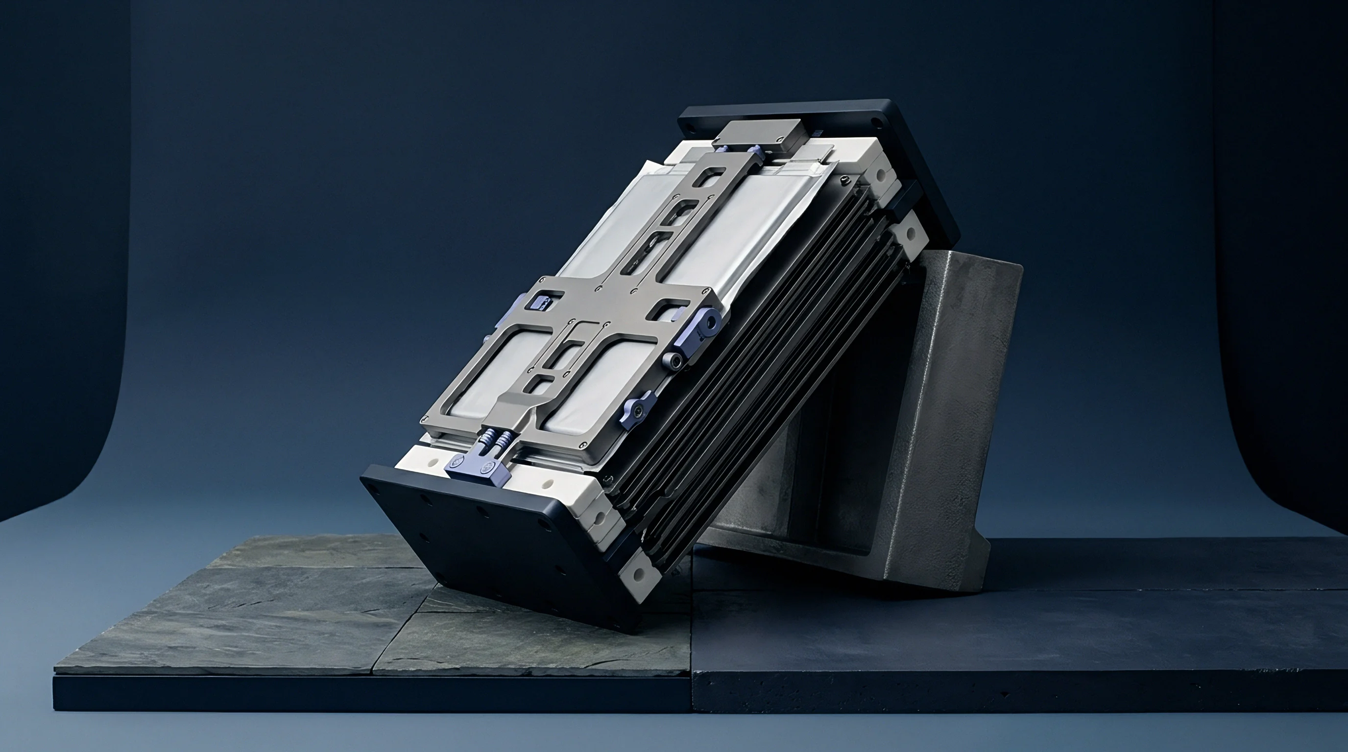
Constraint
Lithium-ion pouch cells expand and contract both reversibly and irreversibly over charge and discharge cycles. As lithium ions intercalate and deintercalate within host lattice structures, microscopic volume changes build up across hundreds of stacked double-sided electrode layers. Without external restraint, this produces macroscopic swelling normal to the cell surface, leading to rapid capacity fade, localized delamination, and early lithium plating as active material particles lose contact with current collectors.
Maintaining surface pressure preserves physical contact across the interfaces, stabilizes SEI layers, and keeps current distribution uniform across the planar footprint.
Pouch cells expand as lithium enters the anode.

Mechanics of Pouch Swelling under Compression
Volume changes inside the cell stem from phase transformations in active electrode materials during lithiation. Graphite anodes expand by roughly 10 percent when fully lithiated to LiC6, whereas high-silicon composite anodes can swell by over 300 percent at the particle scale. Under external constraint, this internal expansion pushes directly against clamping surfaces as normal mechanical stress.
The rate of thickness change tracks state of charge, temperature, and C-rate. Reversible expansion follows state of charge directly, while irreversible swelling builds over cycle life through SEI growth, gas generation, and microcracking.
Steel fixtures bend under sustained loads.
Test fixtures must replicate the mechanical boundary conditions of the target pack architecture if characterization data is to reflect actual field behavior. Rigid endplates maintain a near-constant-volume boundary, forcing cell expansion to manifest as rising internal pressure. Designs built around compressible foam or spring retention maintain a near-constant-force boundary instead.
Running a load frame in the wrong actuation mode produces thermal models and degradation curves that misrepresent pack-level performance.

Pressure Concentration Risks across Flexible Laminates
Because flexible aluminum-polymer pouch envelopes lack the structural stiffness of prismatic or cylindrical hard cans, internal forces transfer directly to external clamping surfaces. Uneven pressure across the cell creates localized force peaks and variations in current density. High-pressure zones drive out electrolyte and concentrate mechanical stress, while low-pressure areas suffer from higher contact resistance and trapped gas pockets.
| Applied Surface Pressure (MPa) | Initial Impedance Shift (1 kHz) | Capacity Retention at 500 Cycles | Dominant Failure Mechanism |
|---|---|---|---|
| 0.05 | +14% baseline | 74.2% | Interfacial delamination and gas pocket isolation |
| 0.30 | 0% reference | 91.8% | Uniform SEI growth and gradual lithium inventory loss |
| 1.00 | -6% baseline | 88.4% | Separator pore closure and localized lithium plating |
| 2.50 | -9% baseline | 63.1% | Particle cracking, internal shorting risk, and separator creep |
Edge effects introduce substantial error into mechanical measurements. Pouch perimeters carry excess aluminum material, thermal seal welds, and tab transitions where the internal stack terminates. Clamping over this seal transfers force onto polymer welds rather than the active electrode area.
To prevent this, frame platens require relief steps matched to the seal geometry so load passes strictly through the active stack footprint.
Applying 0.3 MPa surface pressure reduces capacity fade rate by 22 percent compared to unconstrained pouch cell cycling at 1C rates.
Uneven pressure distribution across flexible pouch envelopes triggers localized lithium plating during fast charging. This causes early micro-shorts and throws off long-term capacity retention models used in pack assembly design.


Rig
Test hardware requires high axial stiffness so cell expansion can be measured independently of frame strain. Load frames for pouch cell testing must hold rigid planar alignment across varying mechanical and thermal loads. Even 20 micrometers of frame deflection under load corrupts force-displacement curves and hides subtle phase-change transitions.
Misalignment degrades measurement accuracy.
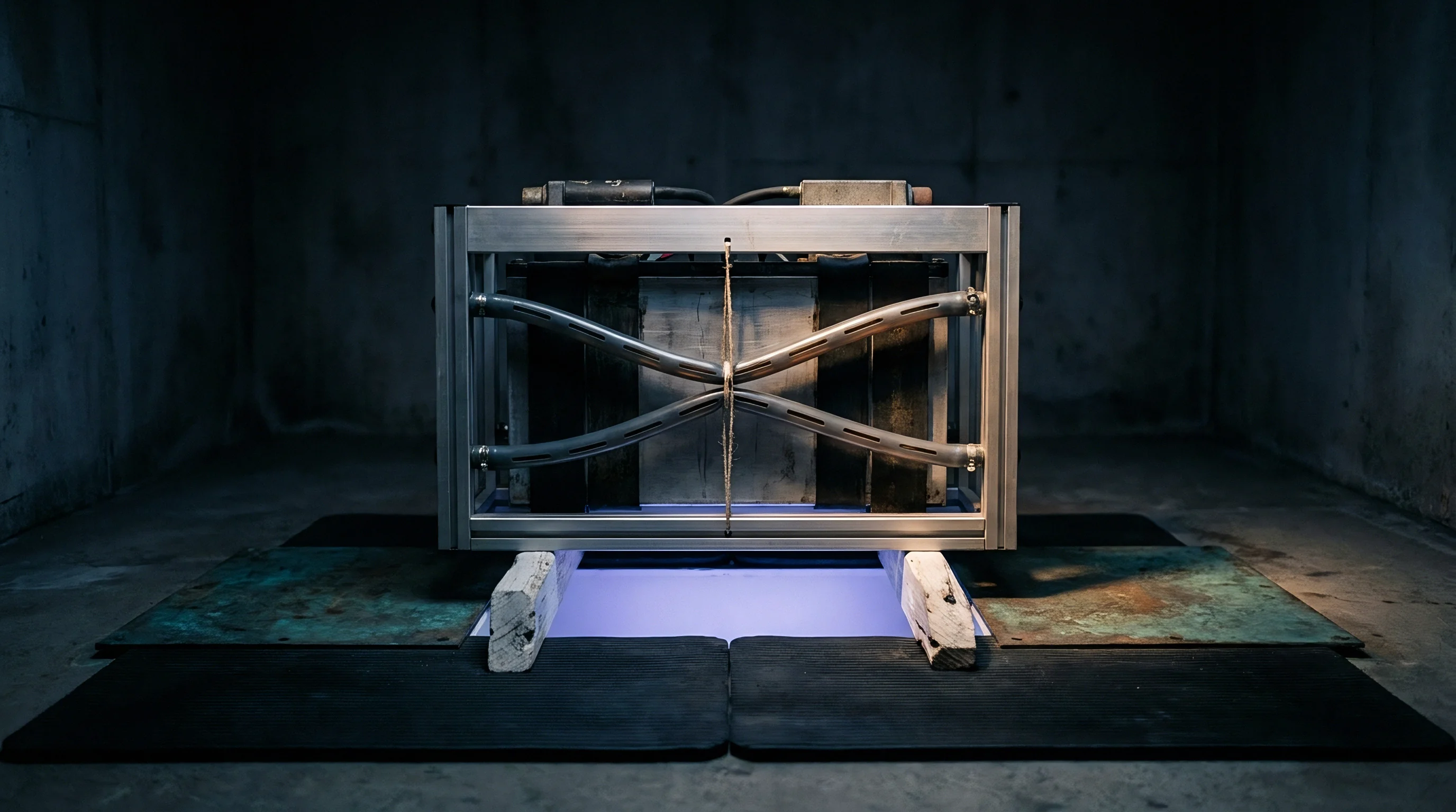
Frame Deflection and Structural Stiffness Targets
Preventing bending deflection requires heavy structural sizing on all load-bearing parts. Universal test machines often introduce parasitic bending when asymmetric swelling tilts the upper crosshead. Dual-column and four-column setups with hardened steel tie rods resist these bending moments far better.
Frame compliance needs to stay under 0.5 micrometers per kilonewton of applied force so fixture flexure does not obscure actual cell thickness changes.
Spherical alignment joints placed directly behind loading platens offset minor parallelism variations from manufacturing. Non-parallel cell faces create skewed pressure profiles across flat platens, creating local stress spikes near the edges. Spherical seats prevent parasitic moments by allowing the platen to self-align with the surface profile of the pouch during initial clamping.

Actuation Selection for Constant Pressure versus Fixed Gap
Constant-pressure testing requires active position adjustment as the cell expands. Pneumatic actuators paired with proportional regulators provide low moving mass and steady force control, holding target pressure through rapid swelling. For fixed-gap testing, electromechanical screw drives driven by high-resolution stepper motors lock platen spacing to sub-micron tolerances, measuring peak expansion forces during overcharge or thermal degradation.
Screw drives hold rigid position gaps.
- Mount the load frame base plate to an isolated optical table to eliminate ambient floor vibrations from disturbing low-force displacement sensors.
- Install tie rods and torque load-bearing fasteners in a cross-pattern to specified values to set uniform structural pre-tension across the frame columns.
- Mount the upper fixed platen using a precision-ground spherical seat joint to enable three-axis rotational self-alignment under initial contact force.
- Calibrate load cell offset and set linear displacement sensor zero points using a ceramic gauge block of certified thickness placed between platens.
- Cycle the motion actuator through its full stroke under target pressure to measure fixture compliance curves across the operational force envelope.
Platens flex under heavy surface loads.
Structural deflection in the frame mechanism skews cell thickness measurements long before the load cell reaches its force limit.
Actuators running without active feedback tend to drift under sustained mechanical loads, introducing small pressure variations that distort long-term electrochemical cycle life data.
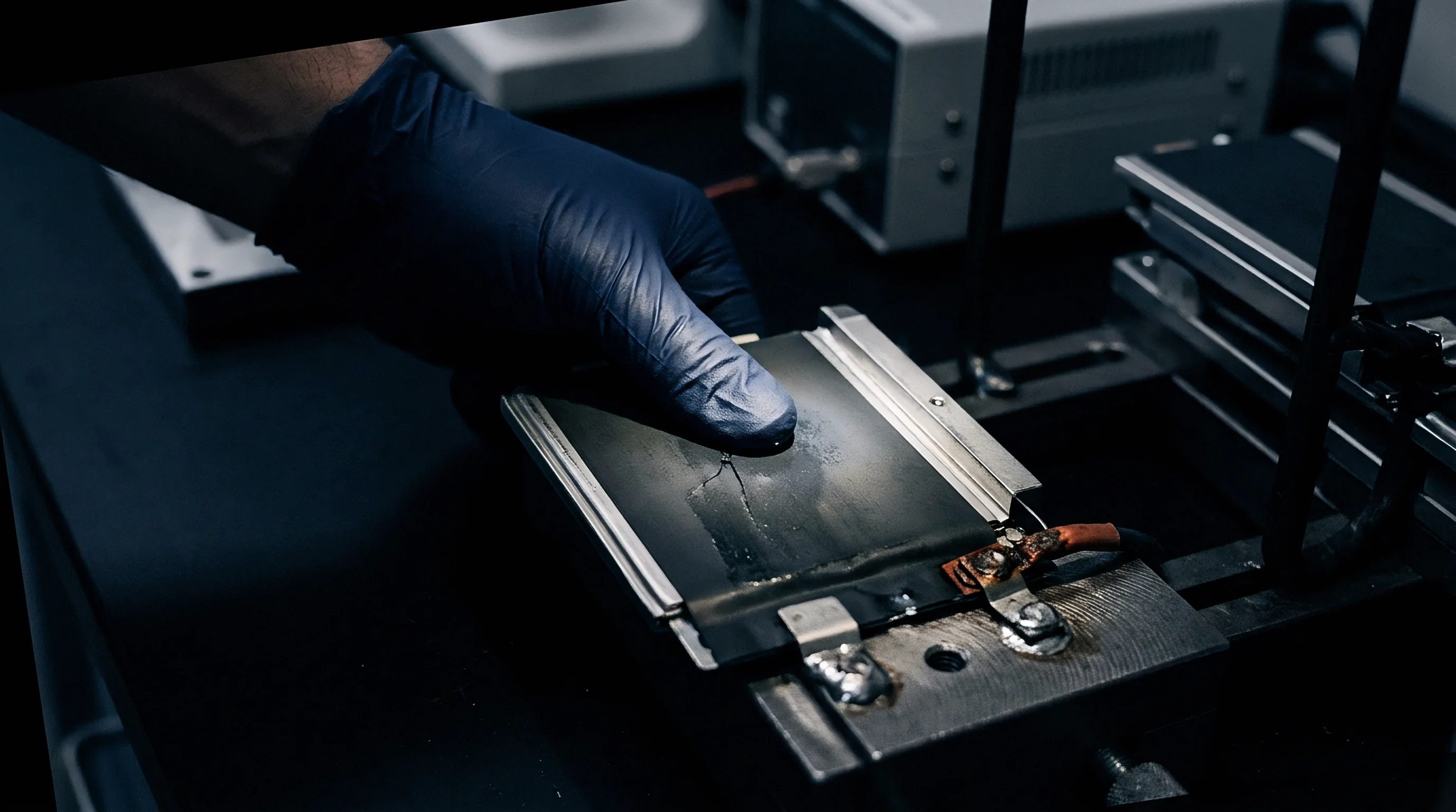

Conduction
Maintaining isothermal boundaries requires fast heat transfer across the platen interface. Characterization load frames act as both mechanical clamps and thermal control systems. Heat generated during high-C-rate discharge must pass smoothly through the platens into liquid cooling loops without letting thermal gradients inside the cell exceed 1.0 °C.
Cooling loops draw off heat.
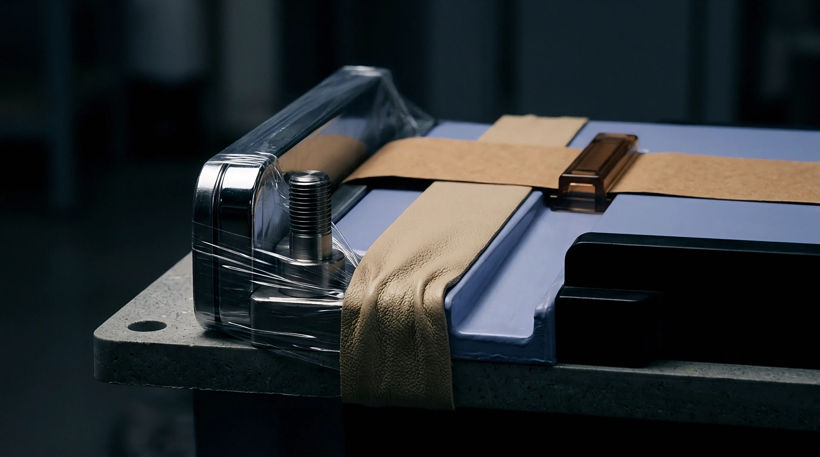
How Does Platen Bending Distort Heat Flux Measurements?
Platen deflection alters thermal contact resistance across the pouch face. Under heavy swelling forces, platens without backing ribs flex outward, dropping pressure at the center relative to the edges. This lower center pressure increases thermal resistance between the pouch laminate and the metal platen, trapping heat near the core of the cell.
Heat flux sensors built into flexing platens then read distorted dissipation values, skewing the microcalorimetric data needed for thermal system design.
Platens are typically machined from high-conductivity metals like oxygen-free copper or aluminum alloys such as 6061-T6 or 7075-T6. Internal channels cut into the platen body optimize heat removal, while counter-flowing serpentine paths prevent temperature gradients across the surface so coolant entering at 25.0 °C leaves with minimal temperature rise across the active cell area.

Thermal Interface Materials under Dynamic Compressive Loading
Choosing thermal pads for compression fixtures requires balancing conductivity against mechanical compliance. Bare metal platens have microscopic surface roughness, creating air gaps that restrict heat flow. Thermal interface materials such as phase-change films, graphite sheets, or soft silicone pads conform to these surface variations and lower thermal contact resistance.
Clamping pressure decays over extended runs.
Thermal interface performance changes with applied compressive stress. Phase-change materials melt into micro-voids at temperatures above 45 °C, reaching thermal impedance below 0.1 °C·cm²/W under 0.3 MPa. Soft silicone pads compress under load, thinning out and improving conductance as surface pressure rises.
Testing routines must account for this pressure-dependent resistance shift when linking surface temperature readings to internal electrochemistry.
Compliance with IEC 62660-1 mandates thermal stability across cell faces within a maximum gradient of 1.5 °C during full-rate characterization.
Consider a 60 Ah silicon-graphite pouch cell measuring 300 mm by 100 mm by 8 mm generating 18 W of heat during a 3C discharge step. Cold plates back high-purity copper platens circulating liquid coolant at 25.0 °C. At an initial preload of 0.1 MPa, thermal interface material resistance sits at 0.45 °C·cm²/W. Across a total active surface area of 600 cm² over both pouch faces, the temperature drop across the interface layer is 1.35 °C. When cell expansion increases surface pressure to 0.5 MPa, pad compression drops interface resistance to 0.22 °C·cm²/W, reducing that temperature drop to 0.66 °C. The resulting 0.69 °C shift in cell surface temperature comes entirely from mechanical pressure changes rather than shifting internal electrochemistry.
External cooling plate temperatures do not reliably match internal cell core temperatures unless interface thermal resistance is validated under load.
Gauge
Precision transducers measure sub-micron displacement and force variations during electrical cycling. Characterizing mechanical degradation requires sensors that capture both static preloads and small dynamic fluctuations caused by phase transitions in the active materials. Sensors mounted in load frames must handle sustained mechanical loads without drifting from environmental shifts.
Temperature shifts distort force signals.

Load Transducer Selection and Thermal Isolation
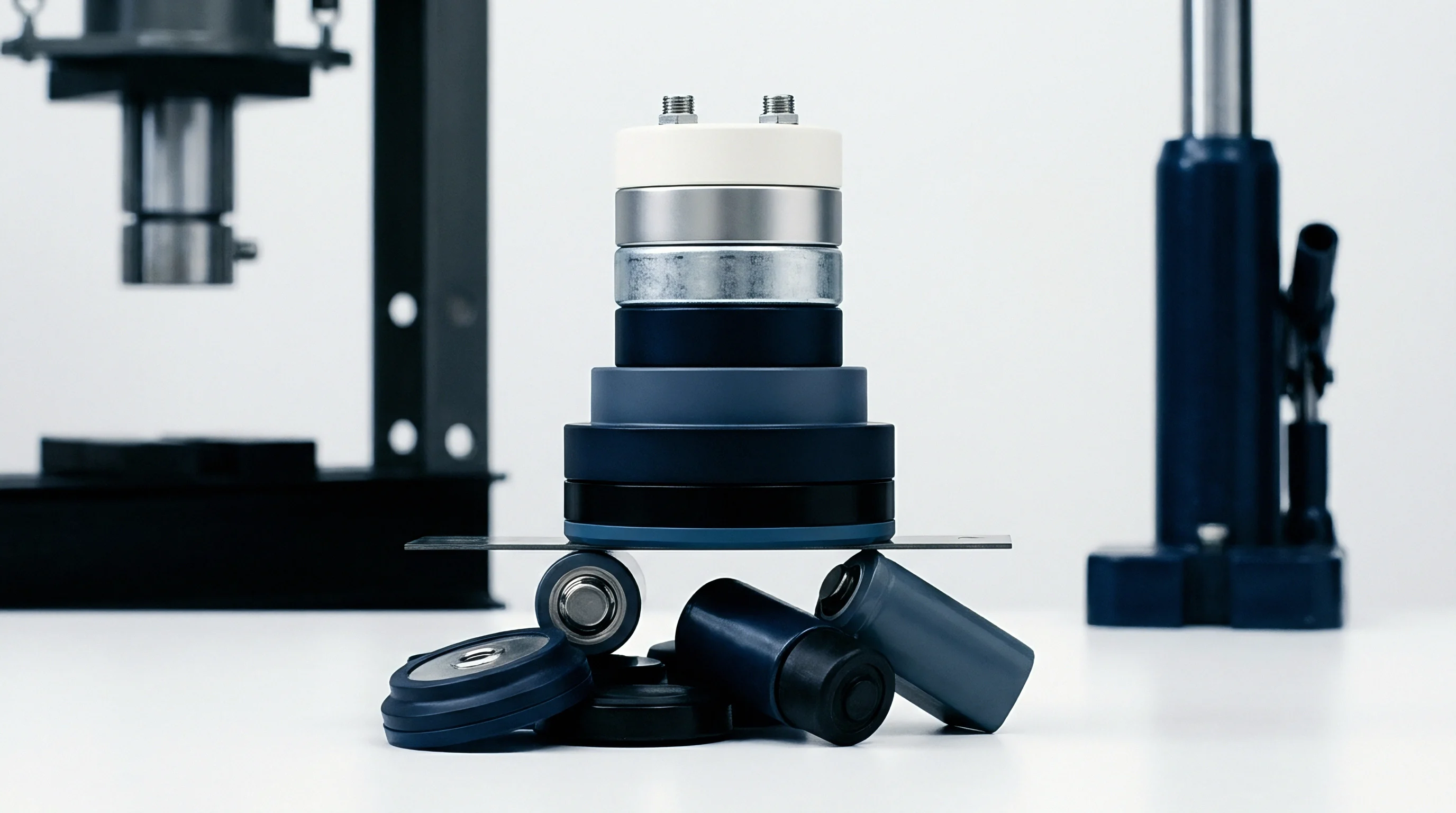
Load cells placed directly in the thermal path suffer zero-point drift when temperatures fluctuate. S-beam and pancake load cells provide high stiffness and axial accuracy, but heat flowing through the sensor body shifts the strain gauge bridge output. Installing ceramic isolation spacers such as zirconia (ZrO2) or high-performance polymers like PEEK between the platens and transducers blocks this conductive heat path.
Pneumatics hold stable clamping loads.
Piezoelectric sensors offer high dynamic force resolution, capturing micro-cracking events inside electrode layers as they occur. Strain gauge load cells provide the long-term stability needed for multi-month cycling tests. Pairing invar load frame components with temperature-compensated bridge circuits keeps lab room temperature swings from showing up as false changes in cell force.
Multi-Point Displacement Sensing across the Cell Face
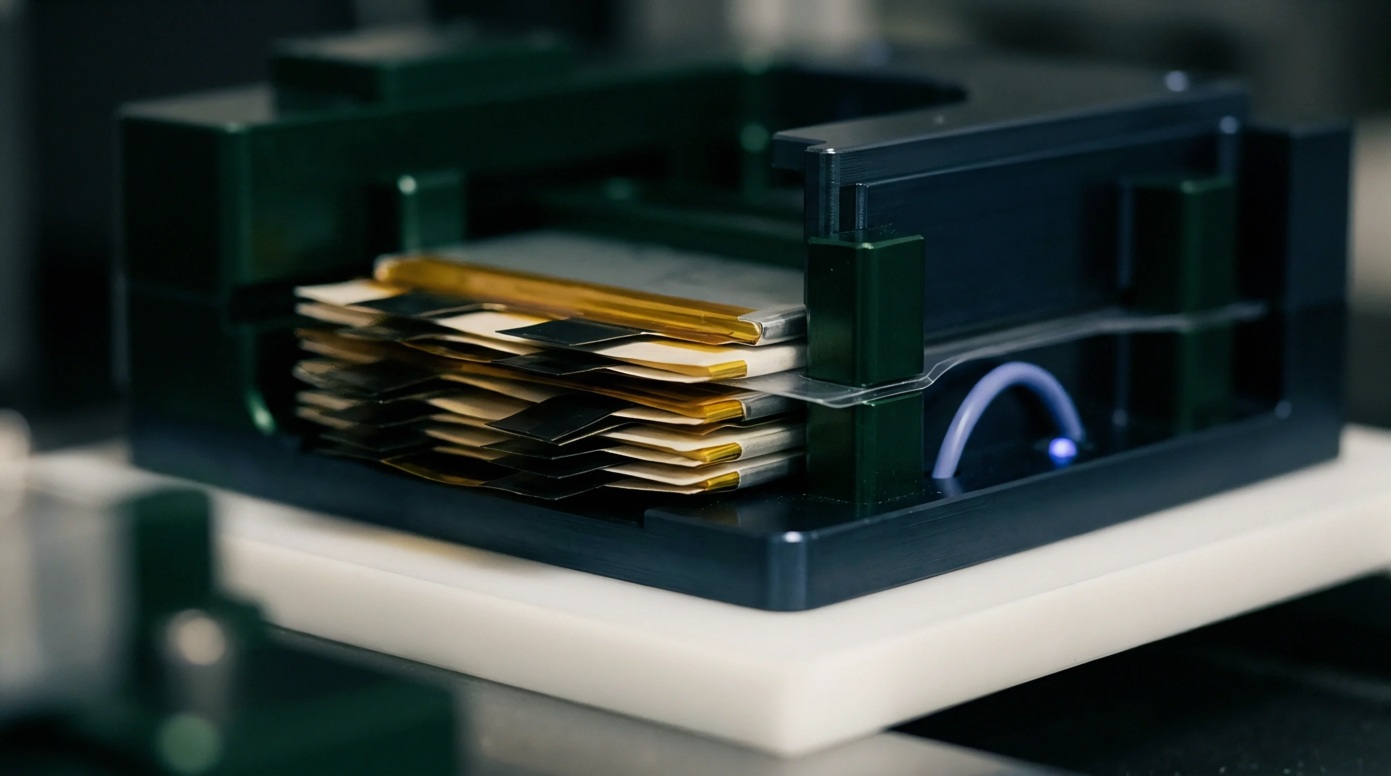
Thickness expansion across a pouch cell face is rarely uniform due to edge constraints and varying current density. Measuring displacement at a single point in the center misses local bulging from gas generation or uneven lithium plating. Multi-point arrays using Linear Variable Differential Transformers (LVDTs) or non-contact optical sensors capture how thickness evolves across the entire surface.
| Sensor Type | Measurement Range | Resolution | Thermal Sensitivity | Mechanical Integration Complexity |
|---|---|---|---|---|
| LVDT (Contact) | ±2.5 mm | 0.1 µm | Low (with invar shafts) | Moderate (requires platen feedthroughs) |
| Laser Triangulation (Optical) | 10 mm | 0.5 µm | Insignificant | High (demands clear optical access) |
| Capacitive Displacement | 1.0 mm | 0.01 µm | High (requires temperature calibration) | High (sensitive to EMI from cyclers) |
| Piezoresistive Load Cell | 0–50 kN | 1.0 N | Moderate (needs ZrO2 thermal barrier) | Low (direct inline mounting) |
Displacement gauges need exact calibration.
- Thermal decoupling hardware prevents heat transfer from hot platens into strain gauge load cells.
- High-bandwidth data acquisition cards capture transient mechanical force spikes during fast-charging steps.
- Differential displacement tracking systems subtract structural load frame compliance from net measured pouch thickness.
- Multi-channel optical sensors monitor planar surface deformation without exerting physical contact forces on cell envelopes.
Uncompensated thermal expansion of structural steel tie rods creates fictitious cell swelling data during isothermal temperature steps.
Under ISO/IEC 17025 calibration procedures, displacement transducers must undergo multi-point verification across their full scale using NIST-traceable gauge blocks under simulated thermal swings from 15 °C to 45 °C before datasets can be accepted into compliance records.


Margin
Data validity boundaries determine how reliably test measurements translate into battery pack engineering. Characterizing mechanical behavior under temperature control provides the data needed to size pack compression springs, tune BMS swelling models, and define structural safety limits. Clear test boundaries protect load frame hardware while keeping cells safe during aggressive testing routines.
Heat spreads sideways through copper.

Defining Ownership Seams in Characterization Data Dossiers
Translating cell test specifications into production drawings requires separating fixture compliance from actual cell expansion. Test dossiers for cell procurement must document frame stiffness, temperature stability margins, and signal noise alongside force-displacement metrics. Omitting fixture compliance details often leads pack designers to over-spec compression foam, adding unnecessary volume and weight to the battery enclosure.
Setting clear seams between supplier test data and internal qualification results prevents disputes over warranty coverage. Vendor qualification testing often runs under ideal, unconstrained lab conditions that inflate cycle-life figures. Requiring characterization data collected in load frames that match actual pack pressures and operating temperatures yields a defensible baseline for accepting or rejecting cell production lots.
Thermal Runaway Containment in Mechanical Characterization Frames
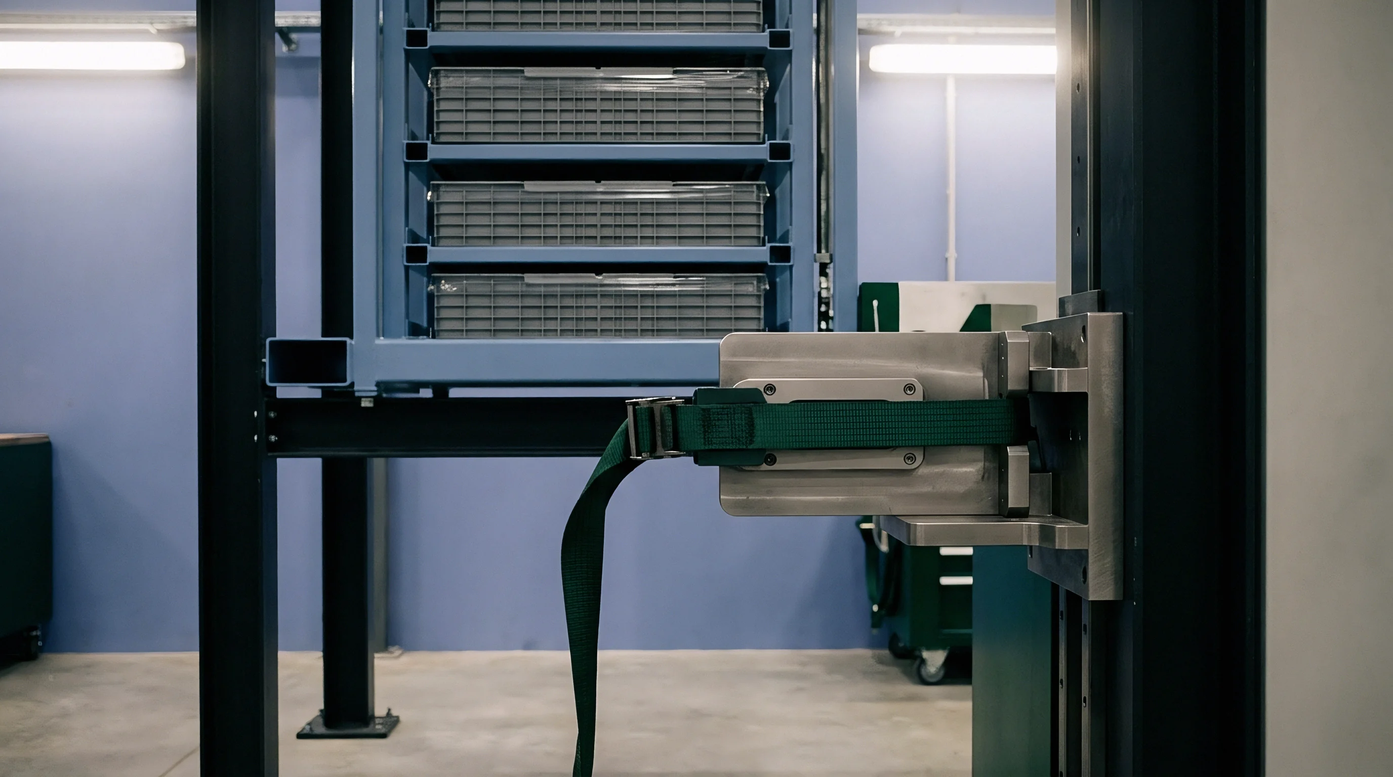
Fixtures holding pouch cells during high-C-rate testing risk heavy damage during sudden thermal failure. High-energy cells under thermal or mechanical stress can rapidly vent toxic gases, shower molten material, and go into full thermal runaway. Load frames in environmental chambers require blast-mitigation features to protect lab equipment and personnel.
Liquid cold plates control surface heat.
- Pneumatic emergency dump valves release applied mechanical forces immediately upon detecting anomalous temperature spikes on cell tabs.
- Stainless steel blast shields enclose the platen assembly to prevent high-velocity cell debris from striking environmental chamber walls.
- Corrosion-resistant platen coatings resist chemical attack from hydrofluoric acid generated during electrolyte decomposition.
- Isolated electrical isolation layers prevent high-voltage tab arcing from grounding through frame columns into sensitive sensor electronics.
- In-line thermal fuse interlocks cut cycler channel current if platen temperature exceeds upper safety thresholds.
Silicon composite anodes expand faster.
- Structural frame yielding caused by unconstrained cell expansion during thermal runaway events.
- Load cell zero-shift drift driven by continuous heat conduction through uninsulated mechanical platens.
- Platen binding and jamming resulting from thermal expansion misalignment between frame guide columns.
- Fictitious thickness compression readings generated by thermal expansion of load frame tie rods during ambient temperature sweeps.
How much parasitic frame compliance can automated thickness-tracking routines tolerate before real-time BMS state-of-health models fail to separate normal SEI growth from lithium plating in high-density pouch cells?