Tolerance Stack Calculations for Prismatic Battery Module Enclosures
Prismatic module enclosures require coupled statistical stacks combining cell manufacturing tolerances with non-linear compression pad and swelling dynamics.
Envelope
Exterior tolerances across the thickness, width, and height of standard aluminum-cased lithium iron phosphate cells set the physical boundaries for module packaging. Manufacturers specify nominal dimensions at twenty-five degrees Celsius on free, unconstrained cans, whereas operational modules hold these cells under active preload ~ a gap that immediately separates catalog specifications from assembly-line reality. A format measuring seventy-one millimeters wide, one hundred seventy-three millimeters tall, and twenty-seven millimeters thick carries independent tolerances along each axis, with thickness showing the widest percentage spread because of can-wall deep-drawing variance, jelly roll winding tension, and electrolyte fill volume.
As stamping dies for prismatic aluminum cans wear down across extended production runs, the center of the broad faces domes outward. This bulging alone adds between zero point two and zero point eight millimeters to uncompressed thickness measurements. Across a series stack of six to twenty-four cells, those variations compound along the primary module axis unless managed directly.
Sizing the structural enclosure therefore requires accounting for every physical interface between the bare aluminum casing and the pack chassis.
Mechanical Boundaries for Prismatic Formats
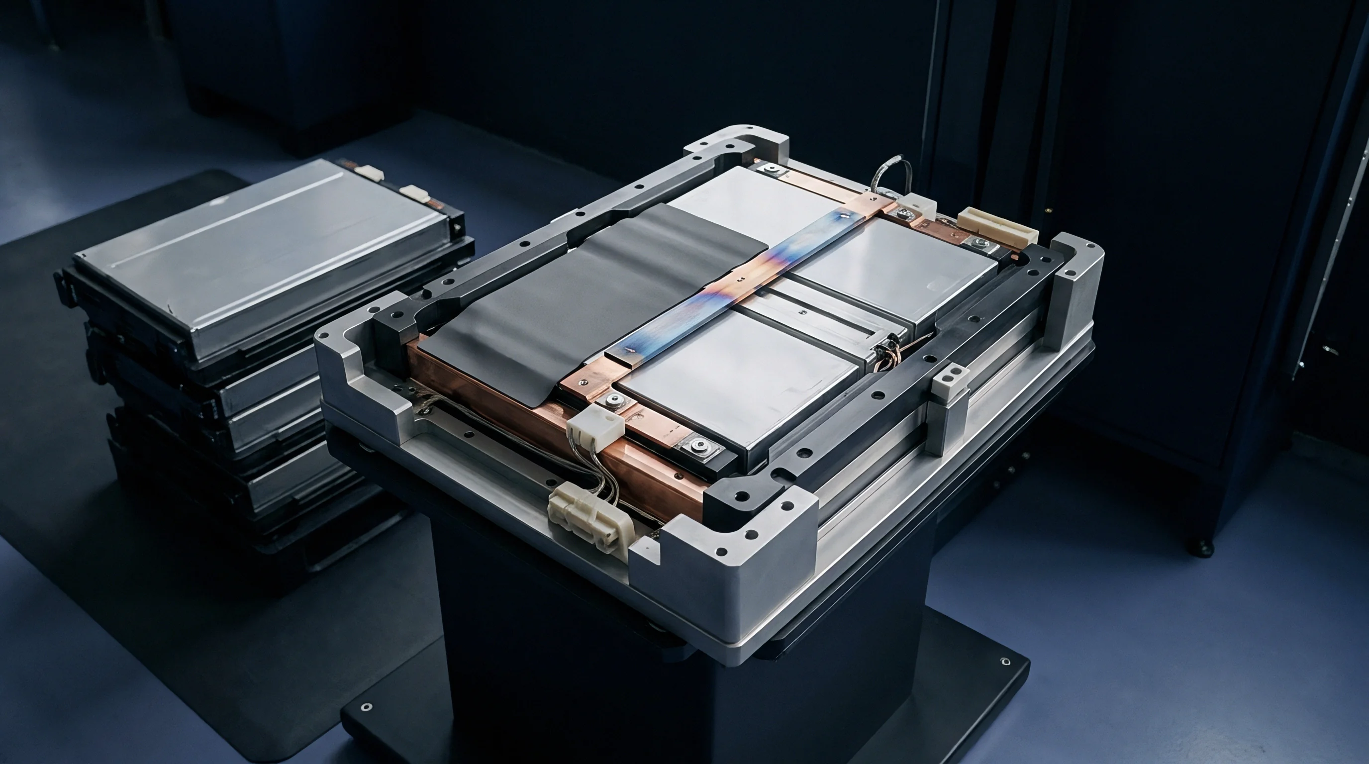
Dielectric isolation wraps of shrinkable polyethylene terephthalate film add between zero point zero five and zero point one two millimeters to each side of the can. Adhesive transfer tapes introduce further stack variance, varying by up to twenty micrometers per bond line, while automated film-wrapping tools leave seam overlaps that create localized high spots. Once the pack reaches its clamping preload, those high points concentrate mechanical stress directly into the can wall.
| Component Layer | Nominal Size (mm) | Lower Tolerance (mm) | Upper Tolerance (mm) | Distribution Type |
|---|---|---|---|---|
| Bare Prismatic Cell Thickness | 54.00 | -0.30 | +0.60 | Skewed Normal |
| Dielectric PET Insulation Wrap | 0.08 | -0.01 | +0.02 | Uniform |
| Aerogel Barrier Sheet | 1.50 | -0.15 | +0.25 | Normal |
| Epoxy Adhesive Film | 0.12 | -0.02 | +0.04 | Uniform |
| Aluminum End Plate Thickness | 15.00 | -0.10 | +0.10 | Normal |
| Side Tension Band Length | 980.00 | -0.50 | +0.50 | Normal |
Simple linear tolerance stacks consistently overestimate total length: adding every worst-case upper bound yields an oversized enclosure that cuts directly into gravimetric energy density. Relying solely on unadjusted statistical limits, on the other hand, risks physical interference during robotic cell insertion. Structural design balances these cell tolerances against the mechanical compliance of the module frame.
Datum Planes and Boundary Stacks
Rigorous datum selection keeps tolerance loops from propagating across axes. The bottom faces of the cells establish the primary vertical datum where they seat against an insulating, thermally conductive interface pad, while a fixed structural end plate defines the longitudinal start point. Lateral guides locate cell width without pinching the aluminum walls.
Before cells proceed to stacking, automated fixtures record these baseline dimensions under controlled platen pressures.

Growth
Lithium-ion cells expand and contract through every cycle as active materials take up and release lithium. During lithiation, the crystalline lattice of natural and synthetic graphite anodes swells up to ten percent along the c-axis at full stage-one lithium carbide formation. At the cell level, this translates to reversible breathing between one and two percent of total thickness across a complete cycle.
Nickel manganese cobalt oxide cathodes show less volumetric change than graphite, but their volumetric shifts still interact with anode swelling to generate measurable casing displacement.
Alongside reversible cycling, continuous solid electrolyte interphase growth drives permanent swelling over thousands of cycles. Reduction reactions consume active lithium and build up inorganic salts and polymeric films across the negative electrode particles. Trace moisture and high-voltage electrolyte oxidation produce gas that further strains the can walls, steadily adding irreversible thickness over calendar and cycle life.
Constrained lithium iron phosphate cells subjected to three thousand full cycles develop continuous mechanical loads between two hundred and four hundred kilopascals against rigid structural boundaries.
Completely rigid enclosures accelerate internal degradation: when an enclosure permits zero mechanical breathing, internal stress levels climb rapidly, exceeding eight hundred kilopascals at high states of charge. That level of compression crushes the porous polyethylene or polypropylene separator, restricting ionic mobility across the liquid electrolyte. The resulting current non-uniformities trigger lithium plating along negative electrode margins during cold fast charging.
Enclosures must incorporate calibrated compliance to balance cell life against physical envelope limits.
Electrochemical Breathing and Irreversible Bulging
The pace of irreversible swelling tracks operating chemistry, thermal exposure, and operational depth of discharge. While lithium iron phosphate exhibits lower lattice strain than nickel-rich formulations during normal cycling, elevated temperatures still accelerate steady interfacial layer formation. Cells incorporating silicon-doped graphite anodes show the most aggressive expansion profiles, generating overall thickness increases exceeding eight percent before reaching eighty percent retained capacity.
Dimensional budgets therefore define distinct boundaries for beginning of life uncompressed states, beginning of life clamped states, and end of life swollen conditions.

Swelling Pressure Development over Cycle Life
Swelling forces map directly to the structural spring rate of the module enclosure. An infinitely rigid frame prevents external dimensional growth at the cost of high internal pressures, whereas compliant framing allows external expansion while moderating internal stack pressure. Sizing analysis resolves this balance by intersecting the non-linear expansion force curves of the cells with the deflection stiffness of the external retention bands.
In field situations, excessive can displacement traces back either to internal pouch-pack delamination or to improper customer preload application.

Shim
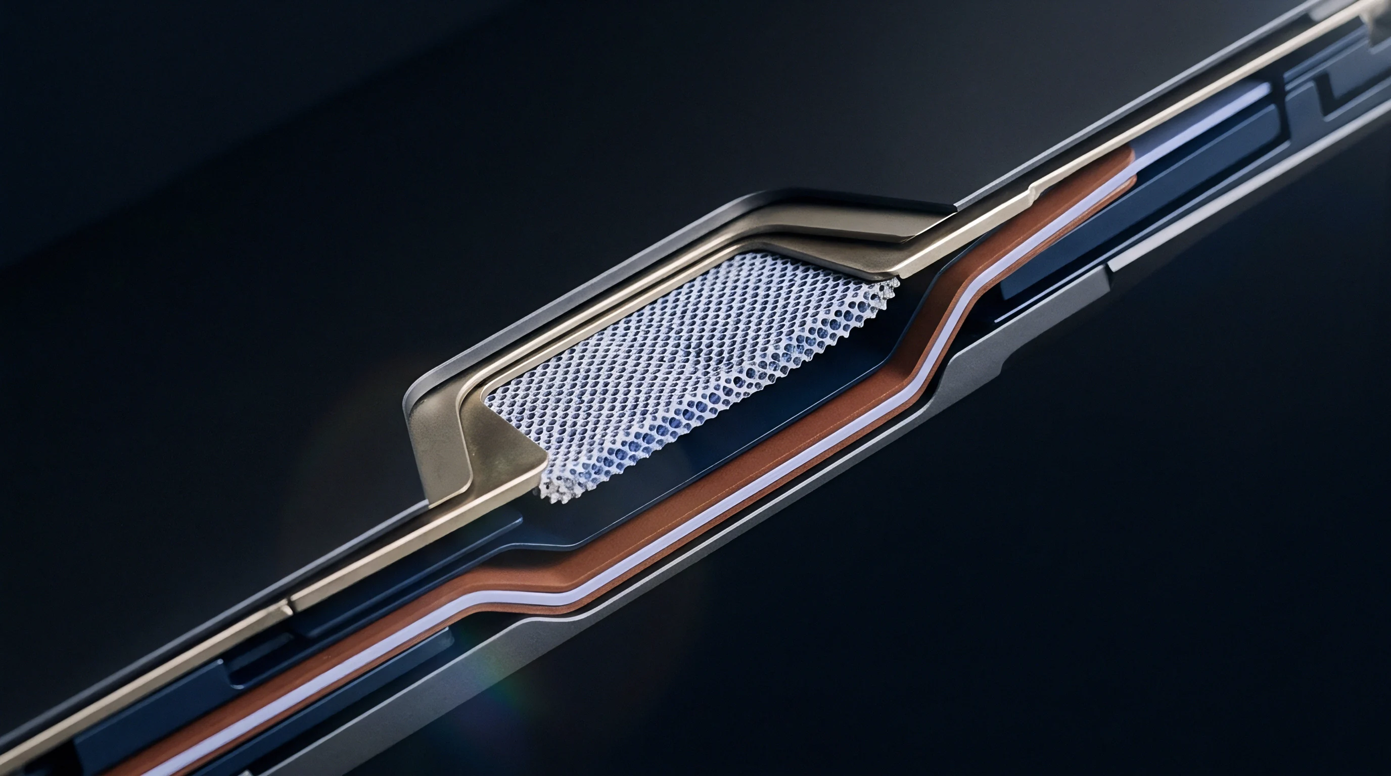
Compliant sheets positioned between adjacent aluminum cell bodies serve as internal spring cushions within the module perimeter. Microcellular polyurethanes, silicone sponges, and ceramic-fiber aerogel blankets each provide this mechanical decoupling, though each introduces a distinct non-linear compression force deflection curve into the stack calculation. As cells breathe reversibly during daily cycling, the compliant pad compresses and expands, absorbing the displacement while holding interfacial contact pressure above thirty kilopascals.
Initial pad compression also takes up piece-part variations across raw cell cans during module clamping. If sixteen adjacent cells each sit at their positive tolerance boundary, the compression pad compresses further during initial tie-plate fastening, elevating beginning-of-life assembly stress. If the cells sit at their lower tolerance limit, the pad experiences less initial compression, risking cell loose-play under road vibration environments.

Which Compression Pad Recovers across Thermal Cycling?
Elastomeric pads display compression set and stress relaxation over extended operational lifetimes. Silicone foams retain elasticity across extreme automotive temperature bands from minus forty to eighty-five degrees Celsius, showing minimal compression set after standardized aging protocols. Polyurethane formulations offer favorable cost structures and progressive stiffness curves, but they experience higher compression set when held under continuous compressive strain at elevated temperatures.
Aerogel materials provide thermal propagation protection alongside mechanical compliance, though their mechanical recovery after repeated cyclic compression is lower than dedicated elastomeric foams.
- Compression force deflection curve governs initial assembly clamping force and subsequent load transfer during cell swelling.
- Compression set percentage dictates the loss of elastic recovery after prolonged exposure to elevated pack temperatures.
- Thermal conductivity rating establishes heat rejection capability across cell-to-cell thermal propagation barriers.
- Dielectric breakdown voltage guarantees electrical isolation between adjacent aluminum can walls under continuous compression.
Chassis components also contract during cold soaks: aluminum structural members shrink at approximately twenty-three parts per million per Kelvin, while steel straps contract at twelve parts per million. Sub-zero storage increases stack pressure if the enclosure contracts faster than the cells and pads shrink. Calculations incorporate temperature-dependent material properties across the full operating range.
Softer compression pads accommodate wide manufacturing spreads while stiffer foams transfer destructive swelling loads directly into structural side members.

Line Compensation and Pad Sorting
High-volume manufacturing lines implement selective grading systems to control stack variance. Automated measuring stations determine the exact thickness of individual cells following the application of insulating films. Control algorithms group cells into matched dimensional sets or select variable-thickness shims to neutralize accumulated lot deviations.
A module containing oversized cells receives thinner compression pads, while a module built from undersized cells incorporates thicker shims. A compliant pad preserves electrical contact pressure across winter thermal contraction while limiting peak structural loading during high-temperature fast charging.
Modulus
The rigidity of module side bands and aluminum end castings governs how much physical breathing the cell jelly roll experiences during high-rate cycling. Structural end plates distribute the concentrated tension of side straps evenly across the face of the terminal cells. Under end-of-life swelling loads exceeding thirty kilonewtons, thin end plates bow outward at their centers.
This deflection relieves pressure at the center of the cell face while concentrating compressive force near the restrained edges, initiating non-uniform electrode utilization across the active coating area.
Predicting end-plate displacement requires modeling the component as a thick plate or structural beam subjected to distributed area loading. Aluminum extrusions feature internal ribs designed to increase the section area moment of inertia without adding dead mass. Steel tension straps welded or bolted to the end plates stretch elastically under these swelling loads, acting as tension springs in series with the compression pads.
| Structural Material | Elastic Modulus (GPa) | Yield Strength (MPa) | Thermal Expansion (10⁻⁶/K) | Density (g/cm³) |
|---|---|---|---|---|
| EN AW-6063-T6 Extrusion | 69.0 | 210 | 23.4 | 2.70 |
| EN AW-6082-T6 Machined Plate | 70.0 | 260 | 23.1 | 2.70 |
| AISI 304 Stainless Steel Band | 193.0 | 290 | 16.0 | 8.00 |
| High-Strength Low-Alloy Steel | 210.0 | 450 | 12.0 | 7.85 |
| Die-Cast Magnesium AZ91D | 45.0 | 150 | 26.0 | 1.81 |
Laser welding side straps to cast end plates produces heat-affected zones with reduced yield strength. Cyclic swelling creates alternating tensile stresses across these welded seams; if the enclosure stiffness is too high, cyclic stress amplitudes accelerate joint fatigue. The structural designer tunes enclosure compliance to keep peak cyclic stresses below fifty percent of base metal fatigue thresholds.
Structural Compliance of Enclosure Restraints
Side strap elongation follows Hooke’s law up to material yield limits. The total mechanical elongation depends on the cross-sectional area of the strap, its active length spanning the cell group, and the elastic modulus of the chosen alloy. Stainless steel provides high elastic modulus, reducing strap stretch to one-third that of aluminum straps of identical geometry.
This stiffness restricts exterior growth, redirecting expansion work into pad compression.
Thermal Expansion and Chassis Deflection
Mismatched thermal expansion coefficients alter module internal preloads across environmental qualification regimes. Operational heating expands the aluminum cell cans faster than external steel tension bands expand. An assembly balanced for two hundred kilopascals of preload at room temperature reaches significantly higher stress levels at fifty degrees Celsius purely through thermal expansion differentials.
The degree to which microscopic weld yield in aluminum module side straps relieves or concentrates fatigue stress during automotive shock profiles remains an active dispute between simulation teams and physical test facilities.

Variance
Engineers calculate overall assembly stack limits using statistical techniques balanced against physical worst-case envelopes. The linear worst-case method sums every individual upper and lower tolerance limit directly. This approach guarantees that physical interference cannot occur, regardless of component combinations.
It assumes every cell, pad, and bracket sits simultaneously at its extreme dimensional limit. In high-cell-count modules, worst-case calculations demand excessively large packaging margins, driving down energy density and increasing enclosure mass.
Actual manufacturing dimensions cluster around the nominal mean according to normal or slightly skewed distributions across production lots. Root Sum of Squares methods calculate the statistical likelihood of extreme combinations, establishing realistic manufacturing clearance boundaries. When component distributions follow predictable Gaussian bell curves, the standard deviation of the complete assembly equals the square root of the sum of individual variance squares.

Should Root Sum Square Replace Worst Case Models?
Pure linear statistical models produce dangerous assumptions when applied directly to battery modules. Standard Root Sum of Squares calculations assume completely rigid parts that do not deform when touching adjacent surfaces. Battery modules contain elastomeric compression pads that deform non-linearly under load.
A simple Root Sum of Squares model also assumes that dimensional deviations are completely independent, yet cells from a single supplier production batch often share common thickness offsets driven by slurry coating weights or separator lot thicknesses.
- Determine unconstrained dimensional means and three-sigma limits for every mechanical layer from supplier production capability data.
- Establish non-linear load-deflection equations for the selected compression pad materials across operating temperature envelopes.
- Define structural deflection functions for the end plates and side tension straps under applied longitudinal loads.
- Calculate the beginning-of-life clamped assembly stack length using numerical equilibrium iterations between pad compression and strap tension.
- Superimpose cyclic reversible breathing and end-of-life irreversible swelling displacements onto the baseline cell thicknesses.
- Solve the coupled non-linear mechanical equilibrium equations to evaluate peak end-of-life structural stresses and total module expansion.
To account for process mean drift, tool wear, and non-normal distribution shapes in incoming lots, a static Bender correction factor between one point three and one point six scales Root Sum of Squares values upward. Advanced pack programs apply Monte Carlo simulations, generating ten thousand virtual module builds by sampling real supplier coordinate-measuring-machine datasets.
Worst-case arithmetic stacks force structural enclosures to consume excess pack volume that statistical distributions show remains empty throughout the operating life.

Stepwise Calculation Sequence for Prismatic Arrays
Coupled calculations combine mechanical deflection with electrochemical swelling limits. The calculation begins with bare cell thickness distributions, applies film wrapping layers, inserts compliant pads, and closes the loop around structural retention members. The resulting calculation yields both physical exterior dimensions and expected internal pressure values across the module lifecycle.

Worked Stack Budget for Sixteen Cell Assemblies
A reference module contains sixteen prismatic lithium iron phosphate cells separated by seventeen compliant aerogel insulation pads, bounded by two aluminum end plates, and held by two stainless steel side straps. The engineering target maintains beginning-of-life assembly clamping pressure at fifty kilopascals while capping end-of-life internal stress at three hundred kilopascals.
Assumptions for the baseline uncompressed state:
Bare cell thickness equals fifty-four point zero zero millimeters with a three-sigma tolerance of plus zero point forty millimeters and minus zero point twenty millimeters. Wrapped dielectric insulation adds zero point sixteen millimeters per cell with a tolerance of plus zero point zero two millimeters and minus zero point zero one millimeters. The uncompressed aerogel pad measures one point fifty millimeters with a tolerance of plus zero point fifteen millimeters and minus zero point ten millimeters.
End plates measure fifteen point zero zero millimeters with a tolerance of plus or minus zero point zero five millimeters each.
Linear Worst-Case Maximum Uncompressed Stack Length:
Total Cells Maximum = 16 × (54.00 + 0.40) = 870.40 mm.
Total Insulation Maximum = 16 × (0.16 + 0.02) = 2.88 mm.
Total Pads Maximum = 17 × (1.50 + 0.15) = 28.05 mm.
Total End Plates Maximum = 2 × (15.00 + 0.05) = 30.10 mm.
Maximum Uncompressed Length = 870.40 + 2.88 + 28.05 + 30.10 = 931.43 mm.
Linear Worst-Case Minimum Uncompressed Stack Length:
Total Cells Minimum = 16 × (54.00 – 0.20) = 860.80 mm.
Total Insulation Minimum = 16 × (0.16 – 0.01) = 2.40 mm.
Total Pads Minimum = 17 × (1.50 – 0.10) = 23.80 mm.
Total End Plates Minimum = 2 × (15.00 – 0.05) = 29.90 mm.
Minimum Uncompressed Length = 860.80 + 2.40 + 23.80 + 29.90 = 916.90 mm.
The total linear worst-case uncompressed dimensional variation span equals 931.43 minus 916.90, which is fourteen point fifty-three millimeters. Accommodating a fourteen-millimeter mechanical variation in a rigid enclosure without compliant shimming is physically impossible without crushing cells or leaving them completely loose.
Root Sum of Squares Statistical Stack Calculation:
Assume symmetric three-sigma standard deviations derived from tolerance bands: cell sigma equals zero point one zero millimeters; insulation sigma equals zero point zero zero five millimeters; pad sigma equals zero point zero four millimeters; end plate sigma equals zero point zero一七 millimeters.
Assembly Variance = (16 × 0.10²) + (16 × 0.005²) + (17 × 0.04²) + (2 × 0.017²).
Assembly Variance = 0.1600 + 0.0004 + 0.0272 + 0.0006 = 0.1882 mm².
Assembly Three-Sigma Stack Deviation = 3 × √(0.1882) = 3 × 0.4338 = 1.30 mm.
Nominal Uncompressed Length = (16 × 54.00) + (16 × 0.16) + (17 × 1.50) + (2 × 15.00) = 864.00 + 2.56 + 25.50 + 30.00 = 922.06 mm.
The statistical three-sigma uncompressed stack envelope spans between 920.76 millimeters and 923.36 millimeters. The total statistical variation span is two point sixty millimeters, compared to fourteen point fifty-three millimeters under the arithmetic worst-case model.
To seat components and maintain contact pressure, an automated module pack line applies a calibrated hydraulic press to compress the assembly to a fixed nominal fixture length of 912.00 millimeters, compressing the seventeen aerogel pads from their nominal total thickness of 25.50 millimeters down to 15.44 millimeters. This initial deflection absorbs the two point sixty millimeter statistical stack variance while establishing fifty kilopascals of initial seating pressure. Under end-of-life conditions, each cell expands by zero point eighty millimeters.
The resulting displacement drives the pads deeper into their compression curves, elastically elongates the steel side straps by zero point forty-five millimeters, and deflects the end plates by zero point thirty millimeters, maintaining final peak pressures below structural limits. Underestimating the cumulative statistical stack produces fractured end-plate retention bolts, sheared busbar laser welds, and unseated thermal interface paste during end-of-life thermal runaway propagation tests.

Closure
Terminal interconnects accommodate displacement vectors arising from cell stack expansion along the longitudinal axis. Aluminum or copper busbars welded across adjacent cell terminals cannot behave as rigid structural links. As cells breathe cyclically and swell permanently, terminal centers shift outward away from the module center datum.
A sixteenth cell in a series string experiences cumulative axial displacement equal to the sum of all preceding cell expansions.
To accommodate this movement, fabricated busbars feature formed expansion loops, omega bends, or laminated foil layers between terminal weld pads. These flexible profiles lower mechanical reaction forces transmitted into the cell terminal glass-to-metal or polymeric seals. If a busbar is excessively stiff, cell swelling forces shear the internal terminal rivets or crack the top lid seal, causing slow electrolyte leakage and insulation resistance faults across the high-voltage bus.

Busbar Interconnect Compliance across Module Axes
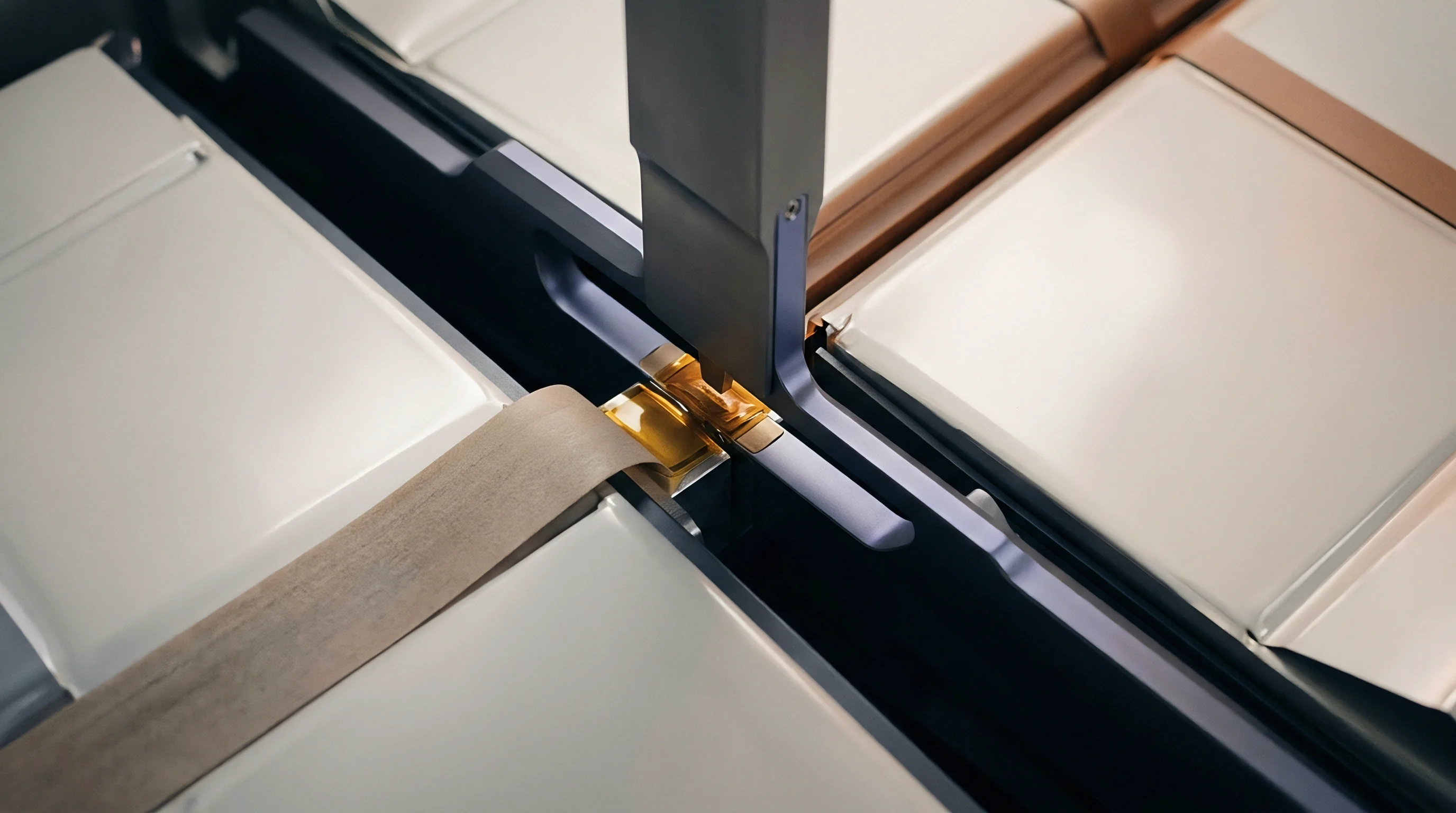
Laser welding processes require tight fit-up tolerances between the busbar contact surface and the cell terminal top face. Gap variations prior to laser firing cannot exceed zero point one zero millimeters without risking weld spatter, blow-through, or incomplete fusion. Height variations among cells within the assembled stack directly consume this welding process tolerance.
If the vertical datum does not hold cell tops co-planar within zero point two millimeters across the entire row, automated vision systems fail or laser focus parameters drift out of specification.
- Unconstrained cell thickness limits define physical receiving inspection rejection criteria for bare cans.
- Pneumatic clamp measurement values establish verified compliance under specified factory preload forces.
- Terminal position true-position boundaries govern automated laser welding tool paths and optical recognition pass rates.
- Swelling force degradation thresholds state maximum permissible end-of-life mechanical loads against module end structures.
Beyond halting cell-to-cell thermal propagation with aerogel insulation, structural packaging engineers must balance mechanical retention, cell life, and thermal safety boundaries within a single enclosure design. The module shell must remain stiff enough to prevent loose cells under vibration, compliant enough to prevent cell crushing under electrochemically driven expansion, and open enough to vent hot gases safely during a cell thermal event.
Contract terms specifying cell thickness at zero preload void supplier warranty claims whenever incoming inspection measures bulging without the prescribed pneumatic clamping fixture.

Commercial Boundaries and Interface Drawings
Commercial contracts fail when battery module drawings omit measurement boundary conditions. A drawing note stating cell thickness as fifty-four millimeters plus or minus zero point three millimeters is legally unenforceable without stating the exact clamping pressure applied during measurement. Cell suppliers reject dimensional non-conformance claims if the buyer measures unconstrained bulging cans on an open granite surface plate.
Incorporating an explicit clamping pressure clause into incoming inspection agreements transfers cell distortion liability back to the cell manufacturer whenever unconstrained incoming thicknesses exceed drawing maximums.