Cylindrical Prismatic and Pouch Cells and How Packs Are Built
Cell format selection dictates pack thermal dissipation paths, stack compression mechanics, busbar welding tolerances, and compliance responsibility.


Form
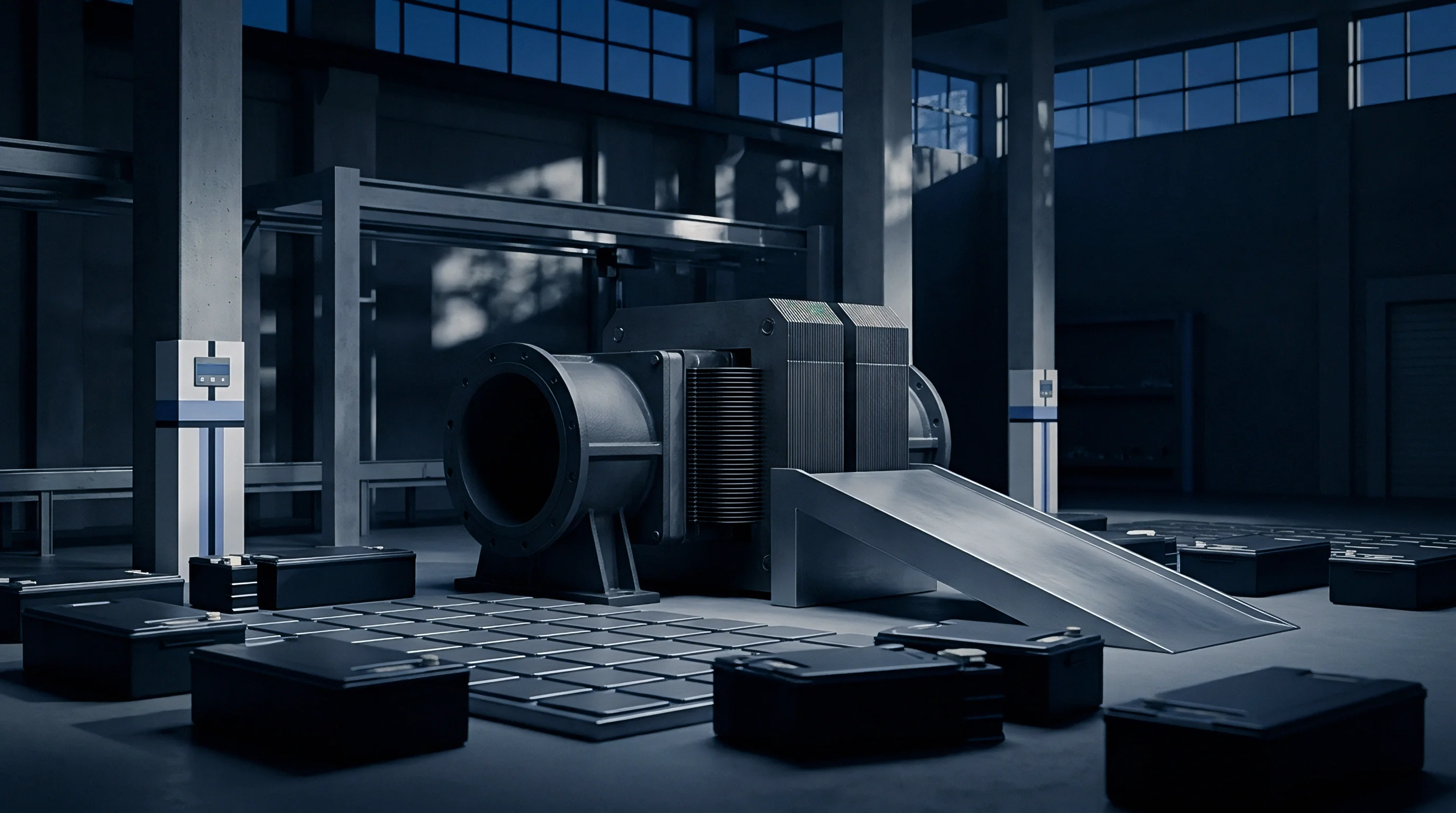
Cylindrical, prismatic, and pouch cell geometries set the baseline where electrochemistry meets mechanical packaging. Choosing a format determines a pack integration team’s volumetric efficiency, mechanical support options, and thermal dissipation paths. Cylindrical cells use a continuous jellyroll wound around a central mandrel and sealed in a rigid metal canister.
Prismatic cells house either wound jellyrolls or stacked electrode sheets in a semi-rigid aluminum alloy case fitted with terminal posts and a burst vent. Pouch cells drop the rigid casing altogether, using heat-sealed aluminum laminate envelopes around flat, z-folded electrode stacks. Each shape comes with distinct mechanical tolerances and packing constraints that shape module tooling and automated assembly lines.
Volumetric packaging efficiency changes substantially between individual bare cells and fully assembled packs. Pouch cells achieve high energy density at the cell level by cutting down dead enclosure space, but their effective pack-level efficiency drops once required expansion gaps, compression plates, and support frames are added. Prismatic cells present flat surfaces that stack cleanly inside enclosures, yielding strong cell-to-pack packing factors without heavy external module frames.
Cylindrical cells leave natural void spaces when arranged in hexagonal or inline arrays; these gaps create built-in channels for air or liquid cooling, though they lower baseline volumetric density.

Mechanical Geometry and Active Volume Ratios
Inside a metal canister or laminated pouch, the ratio of active electrode area to inactive enclosure space determines overall volumetric density. Cylindrical formats like 18650, 21700, and 4680 use spiral-wound electrode assemblies pressed tight against rigid steel or aluminum walls. Steel casing wall thickness usually runs from 0.15 millimeters to 0.25 millimeters on 21700 cells, increasing to 0.50 millimeters to 0.60 millimeters on structural 4680 designs intended to carry chassis bending loads.
The center void left after pulling the mandrel takes up roughly 2 percent to 4 percent of internal canister volume, acting as a pressure relief plenum during thermal events.
Prismatic formats pack active material into rectangular aluminum shells with wall thicknesses between 0.8 millimeters and 1.5 millimeters. Large-format prismatic cells (spanning 100 Ah to 300 Ah) maximize internal volume by arraying multiple flattened jellyrolls or large z-folded stacks side by side. Pouch cells use an aluminum laminate film built from a polypropylene inner seal layer, a 40 to 50 micrometer aluminum barrier foil, and an outer polyamide protective skin.
Total pouch shell thickness remains under 0.15 millimeters, delivering high cell-level density but leaving active components vulnerable to physical punctures and moisture ingress if the perimeter seal degrades.
| Format Standard | Internal Electrode Configuration | Shell Material and Wall Thickness | Cell Volumetric Density (Wh/L) | Typical Pack Packing Factor (%) |
|---|---|---|---|---|
| 21700 Cylindrical | Spiral Wound Jellyroll | Nickel-Plated Steel (0.20 mm) | 680 – 730 | 52 – 58 |
| 4680 Cylindrical | Spiral Wound Tabless Jellyroll | Aluminum Alloy (0.55 mm) | 650 – 700 | 62 – 68 |
| 100Ah Prismatic | Flattened Jellyroll Array | Aluminum 3003 (1.00 mm) | 600 – 640 | 68 – 74 |
| 280Ah Prismatic | Stacked Z-Fold Array | Aluminum 3003 (1.20 mm) | 620 – 660 | 72 – 78 |
| 60Ah Pouch | Stacked Z-Fold Array | Aluminum Laminate (0.12 mm) | 700 – 750 | 50 – 56 |

Jellyroll Winding against Z-Fold Stacking
Whether electrodes are assembled by continuous rotation or stacked layer by layer dictates the internal structure of the cell core. Spiral winding pulls continuous anode, cathode, and separator strips around a spinning spindle under controlled tension. Modern winding lines run above 20 meters per minute for fast throughput, but the process concentrates mechanical stress at the tight inner turns of the jellyroll.
During low-temperature charging, lithium tends to plate at these high-curvature points because current density across the inner layers becomes uneven.
Z-folding feeds a continuous separator web through a reciprocating guide while placing individual double-sided anode and cathode sheets into alternate folds. Stacking eliminates the bending stresses of wound jellyrolls, maintaining uniform current density across the full planar surface of every electrode sheet. Automated stacking keeps edge alignment within plus or minus 0.10 millimeters to prevent anode-overhang misalignment.
Losing that overhang margin creates high-current hot spots that speed up dendrite growth. Stacking lines run slower than winding lines, which raises unit production costs at the cell level.
Tab design varies completely across cell shapes. Standard cylindrical cells use one or two spot-welded nickel tabs running from the internal foil collectors to top cover rivets or bottom cap assemblies. The resistance through these long, narrow tab runs creates localized hot spots during continuous discharge above 2C.
In contrast, tabless 4680 designs laser-weld the uncoated foil edges straight to current collector discs, shortening the electronic path from hundreds of millimeters down to the height of the canister. Prismatic and pouch formats feature wide copper and aluminum terminal tabs ultrasonically welded across all electrode layers to sustain currents over 200 Amperes.
- Separator Wrinkling at Jellyroll Core Local stress peaks during winding create microscopic alignment shifts that lead to internal soft shorts early in cycling.
- Pouch Seal Layer Delamination Hydrofluoric acid generated from trace moisture in the electrolyte attacks the inner polypropylene heat seal, opening pathways for ambient moisture.
- Prismatic Can Swelling and Arching Internal gas buildup pushes flat aluminum sidewalls outward, distorting module mounting structures and misaligning interconnect busbars.
- Tab Fatigue Crack Generation Ongoing vibration transfers dynamic loads into internal foil-to-tab ultrasonic welds, causing fatigue fractures and open circuits.
- Corner Wrinkling in Z-Fold Separators Incorrect web tension during high-speed stacking folds separator edges, letting adjacent electrode layers touch.
Raw material lot tolerances account for capacity variation between shipments.

Thermal
Heat generated during high-rate charging and discharging travels through different paths depending on cell enclosure design. Lithium-ion electrochemistry operates safely between 15 degrees Celsius and 45 degrees Celsius, but degradation speeds up rapidly past 50 degrees Celsius. Thermal management systems have to balance internal heat from Joule losses and entropy shifts against heat shed through cell surfaces.
Because cell geometry dictates the surface area-to-volume ratio available for conduction and convection, engineers must choose between side cooling, tab cooling, or bottom-plate cooling.
Small cylindrical cells provide substantial surface area per unit volume, making side-wall convective air cooling or conductive liquid cooling very effective. But as cell diameter expands from 21 millimeters to 46 millimeters, that surface-to-volume ratio drops by more than 50 percent, inducing steep radial temperature gradients between the core and outer wall. Pouch and prismatic cells present broad, flat faces for direct mounting against liquid-cooled aluminum plates.
Internal heat conduction remains strongly anisotropic: conductivity reaches 20 to 30 Watts per meter-Kelvin parallel to the electrode sheets, but falls below 1 Watt per meter-Kelvin through the thickness of the separator and electrolyte stack.

Heat Transfer Coefficients across Geometry Interfaces
Heat transfer paths through active material layers differ sharply between the axial and radial directions in round cans compared to flat sheets. Inside cylindrical cells, radial heat flow must cross hundreds of alternating foil, separator, and liquid electrolyte interfaces. This keeps radial thermal conductivity low ~ around 0.5 to 0.8 Watts per meter-Kelvin ~ whereas axial conductivity along the continuous copper and aluminum foils hits 30 Watts per meter-Kelvin.
Pulling heat out through the bottom cap or top terminal tab leverages this conductive axial path to curb core heat buildup during heavy charge pulses.
Pouch and prismatic cells shed heat effectively through their main faces when clamped against cooling plates. A thin thermal interface material (TIM) fills surface micro-gaps between the aluminum casing and the cold plate. TIM conductivity usually runs from 1.5 to 6.0 Watts per meter-Kelvin, with compressed bond line thickness held between 0.2 millimeters and 1.0 millimeter.
Inadequate TIM coverage or uneven clamping leaves air pockets that boost interface thermal resistance, causing temperature swings of over 8 degrees Celsius across a single pouch face.
A 4680 cylindrical cell operating at a continuous 3C discharge rate exhibits a center-to-can thermal delta exceeding 18.2 degrees Celsius when conduction is restricted to the bottom puck interface.

Cooling Plate Integration and Boundary Resistance
Bottom cold plates relying on gap pads depend heavily on uniform contact pressure. Aluminum heat sinks with internal channels circulate glycol-water mixtures at flow rates calculated to stay in turbulent flow regimes. The pressure drop through these plates must be weighed against pump power draw in the pack.
Snake-style cooling tubes routed between rows of cylindrical cells offer direct side cooling and stabilize temperatures across large parallel groups, though they introduce extra fluid joints and potential leak points.
Containing thermal runaway propagation is a mandatory safety threshold under UN 38.3 and UL 1973 standards. If an individual cell suffers an internal short and goes into runaway, temperatures quickly top 800 degrees Celsius. In cylindrical layouts, insulation sleeves, aerogel wraps, or phase-change materials wrap each cell to prevent heat from cascading to neighboring units.
Pouch and prismatic packs place compression-resistant ceramic fiber sheets or mica plates between adjacent flat faces. These barrier materials hold up at 1000 degrees Celsius, blocking direct flames and stopping conductive heat transfer to adjacent cells.
| Cell Format | Surface Area-to-Volume Ratio (m⁻¹) | Internal Axial Thermal Conductivity (W/m·K) | Internal Radial/Transverse Thermal Conductivity (W/m·K) | Max Allowable Continuous Current (C-Rate) |
|---|---|---|---|---|
| 21700 Cylindrical | 190 | 28.5 | 0.65 | 3.0C |
| 4680 Cylindrical | 87 | 32.0 | 0.52 | 1.5C |
| 100Ah Prismatic | 42 | 24.0 | 0.85 | 2.0C |
| 280Ah Prismatic | 28 | 22.0 | 0.92 | 1.0C |
| 60Ah Pouch | 115 | 26.0 | 0.78 | 2.5C |
Thermal limits set the ceiling for current. Because embedded physical sensors disturb electrode layers, tracking internal core temperatures relies on calibrated state estimators. Thermocouples placed on negative terminal tabs provide the best practical proxy for internal conditions during heavy discharge pulses.
In sub-zero ambient conditions, cell internal resistance spikes, producing heat that self-heating control loops can use to warm the pack before starting charge acceptance.
How phase-change interface materials degrade under continuous mechanical vibration over a ten-year lifespan in cell-to-pack designs has not been fully quantified in field operation.


Clamp
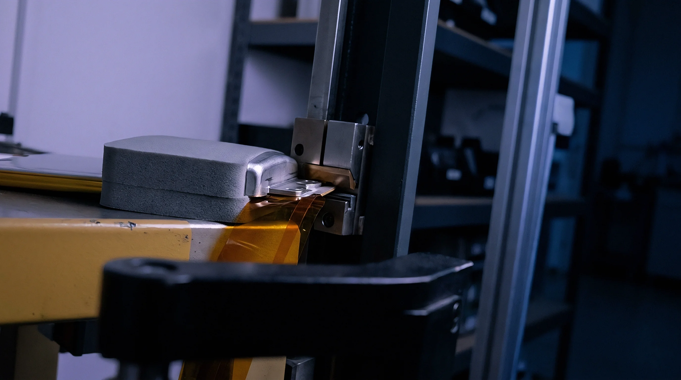
Ongoing electrochemical cycling swells internal cell volumes, forcing external pack structures to manage expansion over the battery’s operational life. Anode materials ~ especially graphite blended with silicon ~ expand during lithiation. At the atomic scale, silicon expands up to 300 percent when fully lithiated, driving macroscopic stack thickness increases of 5 percent to 15 percent over the cycle life.
Without external clamping, pouch and prismatic cells suffer layer delamination, localized gassing, and fast capacity loss. Mechanical restraint systems must balance assembly pre-load against peak end-of-life swelling forces.
Cylindrical cells withstand internal hoop stress through their rigid metal canisters, containing radial expansion without external compression plates. Flat pouch and prismatic cells, by contrast, depend on end plates, tie rods, or spring-loaded side frames to maintain steady, uniform stack pressure. Keeping correct pressure preserves layer-to-layer contact, lowers internal resistance, and stops lithium plating in areas where gaps might otherwise form.
In these formats, the clamping structure acts as both a load-bearing frame and a swelling buffer over the life of the pack.

Pouch Swelling Dynamics and Pressure Maintenance
Lithium intercalation into graphite anodes drives thickness expansion from roughly three percent when new up to twelve percent by end of life. On top of this long-term growth ~ driven by solid electrolyte interphase (SEI) layer buildup ~ cells breathe reversibly during each charge and discharge cycle. New pouch cells are typically assembled under a mechanical pre-load of 100 kilopascals to 300 kilopascals; without this pressure, cycling quickly causes electrode buckling and separator slippage.
Over hundreds of cycles, accumulated growth builds internal compressive stress to 800 kilopascals or even 1.2 megapascals inside rigid frames. If the end plates cannot yield, those forces warp structural fasteners and fracture cooling plate joints. Placing elastomeric compression pads (like polyurethane or silicone foam sheets) inside the stack absorbs dimensional growth.
These foam pads feature non-linear spring rates that absorb expansion while keeping pressure above the minimum threshold needed to prevent electrode separation.
Compliance with IEC 62619 subclause 7.2.2 mandates that pouch cell compression hardware retain dimensional stability within plus or minus 0.15 millimeters under sustained 800-kilopascal expansion loads over 3000 thermal cycles.

Module Enclosure Rigidity and Cell-to-Pack Integration
Structural pack designs remove internal side plates and bond large format cases straight to chassis cross-members. Module-to-Pack (MTP) designs group cells inside local metal trays held by bolts and structural straps. Cell-to-Pack (CTP) skips sub-modules entirely, using high-strength polyurethane or epoxy structural adhesives to bond long prismatic cells directly to the tray floor and side extrusions.
These structural adhesives achieve tensile shear strengths over 12 megapascals while insulating electrically up to 3000 Volts DC.
Module walls take up dynamic loads. Tray bending under road impacts requires finite element analysis to protect bonded joints from fatigue failure. In CTP setups, large prismatic cells contribute directly to the tray’s overall torsional stiffness.
That dual role requires tight control over adhesive bead geometry, open time, and curing conditions during assembly. Voids in the adhesive line can trap moisture and concentrate stress, triggering bond failure under repeated chassis flex.
- Evaluate Peak End-of-Life Swelling Force Calculate predicted expansion pressure at 80 percent state of health to size the end plate section modulus and tie-rod tensile specs.
- Select Elastomeric Compression Pad Stiffness Select foam compression curves that maintain at least 100 kilopascals of pressure at low charge while keeping peak end-of-life pressure under 1.0 megapascal.
- Verify Adhesion Surface Preparation Require plasma cleaning or surface priming on cell casing walls before applying polyurethane structural adhesives.
- Quantify Bending Moment Redistribution Model tray flexure to ensure structural cell-to-pack adhesive joints stay below 3.0 Newtons per millimeter of peel stress during chassis twist tests.
- Set Fastener Pre-Load Torque Window Define torque windows and thread-locking compound specifications for module tie-rod fasteners to stop vibration loosening.
Evaluating module structural designs involves running maximum pack vibration profiles on electrodynamic shakers while monitoring strain across clamping tie rods. In testing of large-format prismatic stacks, unconstrained modules showed rapid internal resistance spikes from micro-fretting corrosion at the terminals.
Underestimating clamping plate thickness caused structural deflection, forcing a full redesign of the module housing and delaying initial production builds by eleven weeks.

Weld
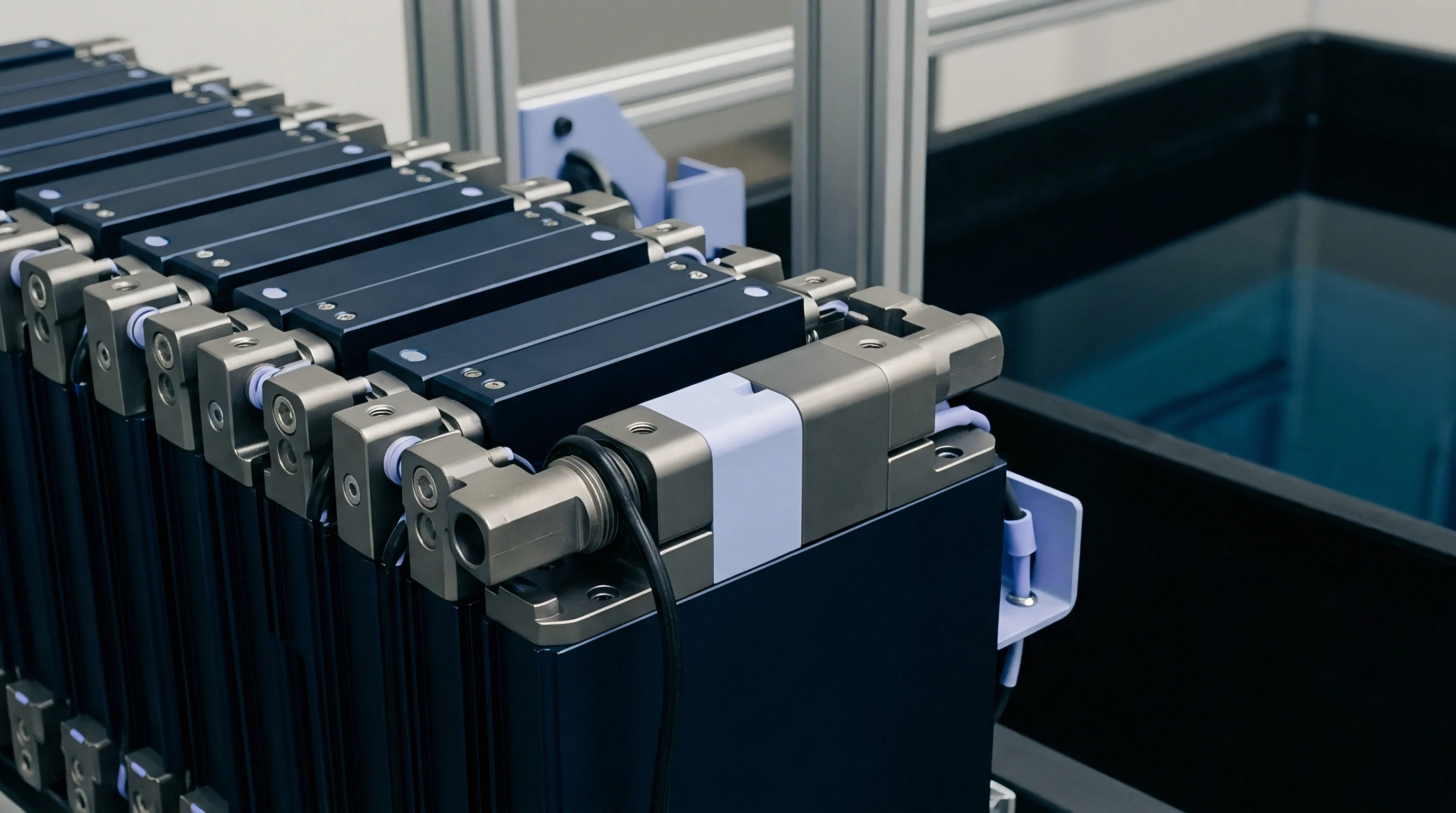
Electrical power flow between cells relies on high-integrity metal connections that endure continuous vibration and thermal cycling. Busbars connect cell terminals in series and parallel to reach the target pack voltage and current capacity. Joining dissimilar metals ~ like copper busbars to aluminum cell terminals ~ creates metallurgical challenges because melting points and thermal conductivities differ widely, risking brittle intermetallic compounds.
Joining methods include laser welding, ultrasonic wedge bonding, micro-resistance spot welding, and mechanical clamping.
Laser joining is the primary high-speed automated method for attaching busbars to prismatic and cylindrical cells. Fiber lasers operating in the near-infrared spectrum (1070 nanometers wavelength) or blue spectrum (450 nanometers wavelength) deliver precise energy density directly into the weld zone. Ultrasonic bonding offers a cold, solid-state alternative, making it ideal for heat-sensitive pouch cell tabs where molten weld pools could burn internal separator films.
Every joining option requires tight control over terminal height variation, surface oxidation, and fit-up gaps.

Laser Joining Mechanics for Copper and Aluminum
Infrared fiber beam energy couples differently into copper and aluminum tabs because of wavelength-dependent reflectivity. Bare copper reflects over 90 percent of 1070-nanometer infrared energy at room temperature, demanding high keyhole initiation power that can cause weld blowout into internal cell parts. Blue lasers running at 450 nanometers boost absorption in copper to over 65 percent, producing conduction-mode weld pools with minimal spatter and penetration depth controlled between 0.3 millimeters and 0.8 millimeters.
Overlap joints require near-zero gap between the underside of the busbar and the top of the terminal. Gaps larger than 10 percent of upper sheet thickness lead to beam drop-through, incomplete fusion, and porosity. Automated clamping fixtures use spring-loaded mechanical fingers to press busbars flat against terminals during welding, holding gaps below 0.05 millimeters.
Real-time monitoring systems track reflected light spectra and thermal images, flagging joints with keyhole instability before packs move down the line.
Direct laser welding of dissimilar terminal metals without nickel-coated transition layers guarantees brittle intermetallic compound formation at the joint interface.

Ultrasonic Bonding and Wire Bonding Alternatives
Solid-state friction joining forms clean metallurgical contacts without melting the metal foils. Ultrasonic wedge bonding applies high-frequency vibrations (typically 20 kilohertz to 40 kilohertz) while pressing a textured sonotrode against stacked pouch tabs or wire leads. Dynamic shear forces break surface oxide layers, causing plastic deformation and atomic diffusion across the boundary.
Because no liquid metal forms, this process avoids brittle intermetallics when joining aluminum straight to copper.
Wire bonding with heavy aluminum wire (300 micrometers to 500 micrometers diameter) adds cell-level fusing to high-density cylindrical modules. If an internal short occurs in one cell, the thin wire acts as a sacrificial fuse, melting under surge current to isolate the failed unit from parallel neighbors. Automated equipment completes individual bonds in under 100 milliseconds, though wire bonds have higher electrical resistance per connection than laser-welded copper busbars.
| Joining Technology | Compatible Material Combinations | Typical Joint Resistance (µΩ) | Tensile Shear Strength (N) | Maximum Gap Tolerance (mm) |
|---|---|---|---|---|
| Infrared Laser Welding | Al-Al, Steel-Ni, Cu-Cu (with coating) | 15 – 30 | 850 – 1200 | 0.05 |
| Blue Light Laser Welding | Bare Cu-Cu, Cu-Al Dissimilar Joints | 8 – 18 | 1100 – 1500 | 0.03 |
| Ultrasonic Heavy Wire Bonding | Al Wire to Cu/Al Terminals | 120 – 250 | 15 – 35 | 0.10 |
| Ultrasonic Tab Wedge Bonding | Multi-layer Al/Cu Foil Stacks | 10 – 25 | 400 – 750 | 0.02 |
| Resistance Spot Welding | Ni Ribbon to Steel Cans | 45 – 90 | 180 – 320 | 0.08 |
- Clean cell terminals using pulsed laser ablation to remove organic residues and surface oxide layers before positioning busbars.
- Position busbar sheets using vision-guided robotic end effectors to align weld slot features within plus or minus 0.03 millimeters of terminal centerlines.
- Apply localized mechanical down-force via pneumatic clamping fixtures to achieve zero interfacial clearance between busbars and terminal faces.
- Execute programmed laser weld patterns while supplying high-purity argon shielding gas at 15 liters per minute to suppress molten pool oxidation.
- Measure four-point DC micro-ohm resistance across every completed joint, rejecting assemblies that exceed 25 micro-ohms total interface resistance.
Joint interfaces suffer fatigue over time. Thermal expansion mismatch between copper busbars and aluminum cell terminals creates cyclic shear stress during heavy charging and discharging. Over thousands of operating hours, these joints risk micro-fretting and fatigue cracking.
Subjecting welded tabs to 1000 thermal shock cycles between minus 40 degrees Celsius and plus 85 degrees Celsius produces up to a 3.2 milliohm contact resistance variance.
Standard IEC 61960 section 5.4 mandates micro-ohm resistance validation across every welded busbar series junction to prevent localized resistive heating.
Harness
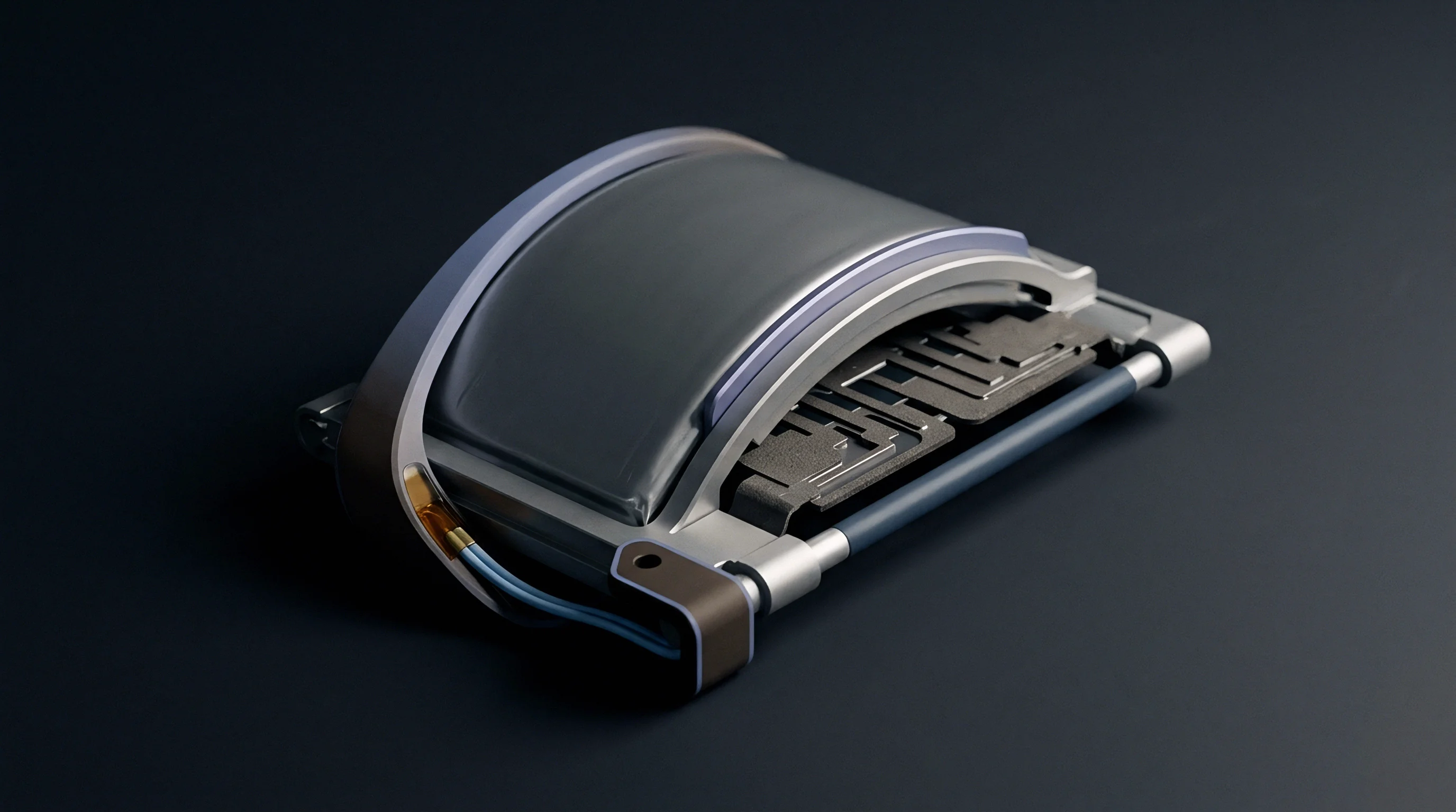
Cell monitoring electronics require physical wiring paths to route voltage and temperature telemetry back to the controller. Battery Management Systems (BMS) rely on precise cell voltage readings (typically within plus or minus 2 millivolts) to calculate state of charge, estimate state of health, and balance cells actively or passively. Designing these signal lines requires layouts that maintain isolation from high-voltage traction bus potentials.
Traditional wire harnesses built from hand-routed bundles add manual labor, weight, and the risk of miswiring during high-volume assembly. Flexible Printed Circuits (FPC) and Flexible Flat Cables (FFC) automate this by integrating dozens of signal traces into thin polyimide films. Mounting passive components ~ like overcurrent protection fuses and thermistors ~ directly onto signal FPCs streamlines assembly and reduces pack part counts.

Flexible Printed Circuit Routing and Isolation
Copper traces etched onto polyimide substrates lower harness weight and eliminate manual wiring mistakes. FPC thickness stays below 0.5 millimeters, running flat across module busbar covers. Nickel-plated copper pads on the FPC line up with cell busbars for joining by ultrasonic welding, laser soldering, or spring pins.
Surface-mount chip fuses wired in series with each voltage sense trace isolate signal lines if a short occurs on the BMS board.
Dielectric isolation must prevent high-voltage arcing between adjacent voltage traces operating at cumulative pack potentials. Polyimide film provides breakdown strength above 100 kilovolts per millimeter. Edge clearances along FPC trace runs must satisfy creepage and clearance distances dictated by operating voltages.
High-current switching noise from adjacent power busbars is managed by routing sense traces as differential pairs or shielding them with continuous ground planes in multi-layer flex circuits.

Creepage Clearance and High Voltage Safety
Dielectric spacing between adjacent series taps follows IPC-2221 standards based on peak voltage differential. In an 800-Volt traction pack, system voltage requires physical clearance distances exceeding 8.0 millimeters across uninsulated board areas under pollution degree 2 conditions. Creepage distances along insulation surfaces must be larger if condensation can form inside the sealed enclosure.
Encapsulating delicate traces in conformal coating or potting compound relaxes spatial clearance requirements while sealing out moisture.
- Inspect raw FPC assemblies for polyimide substrate micro-cracks and trace continuity using automated optical inspection equipment.
- Position the flexible circuit alignment holes over locate pins integrated directly into the plastic module top harness carrier frame.
- Secure signal pads to cell busbar surfaces using low-temperature laser soldering or micro-spot welding techniques.
- Verify fuse resistance values across every integrated surface-mount voltage tap resistor using multi-channel automated test fixtures.
- Connect the master FPC tail connector to the BMS module interface header, verifying positive latch engagement and pin retention force.
Connector pins are frequent failure points in automotive shock and vibration environments. Loose or floating connectors cause intermittent signal drops that trigger false BMS fault codes and unexpected pack shutdowns. Direct-soldered or welded FPC tails eliminate physical plug connectors at module interfaces, boosting long-term reliability ~ though repairing them in the field requires specialized tools.
Flexible printed circuits eliminate assembly wiring mistakes, though they require mechanical support fixtures at every connector interface.


Economics
Financial commitments in pack manufacturing span cell unit costs, tooling expenditures, and certification overhead. Format selection fundamentally alters landed pack economics by setting the line between cell supplier investment and integrator manufacturing burden. Standard commodity cylindrical cells like 21700 offer low cell procurement prices thanks to global factory scale, but require higher assembly automation spending to handle thousands of weld joints and cell holders.
Custom large-format prismatic and pouch designs reduce pack part counts, shifting non-recurring engineering (NRE) and tooling costs upstream into casing dies and sealing machinery.
Cell procurement makes up 60 percent to 75 percent of total completed pack manufacturing cost. The remaining expense covers tray extrusions, cold plates, thermal interface materials, BMS electronics, wire harnesses, structural adhesives, and factory labor. Choosing between off-the-shelf and custom formats determines where engineering ownership, quality liability, and regulatory compliance rest between the cell vendor and the pack integrator.
Non-Recurring Engineering and Tooling Amortization
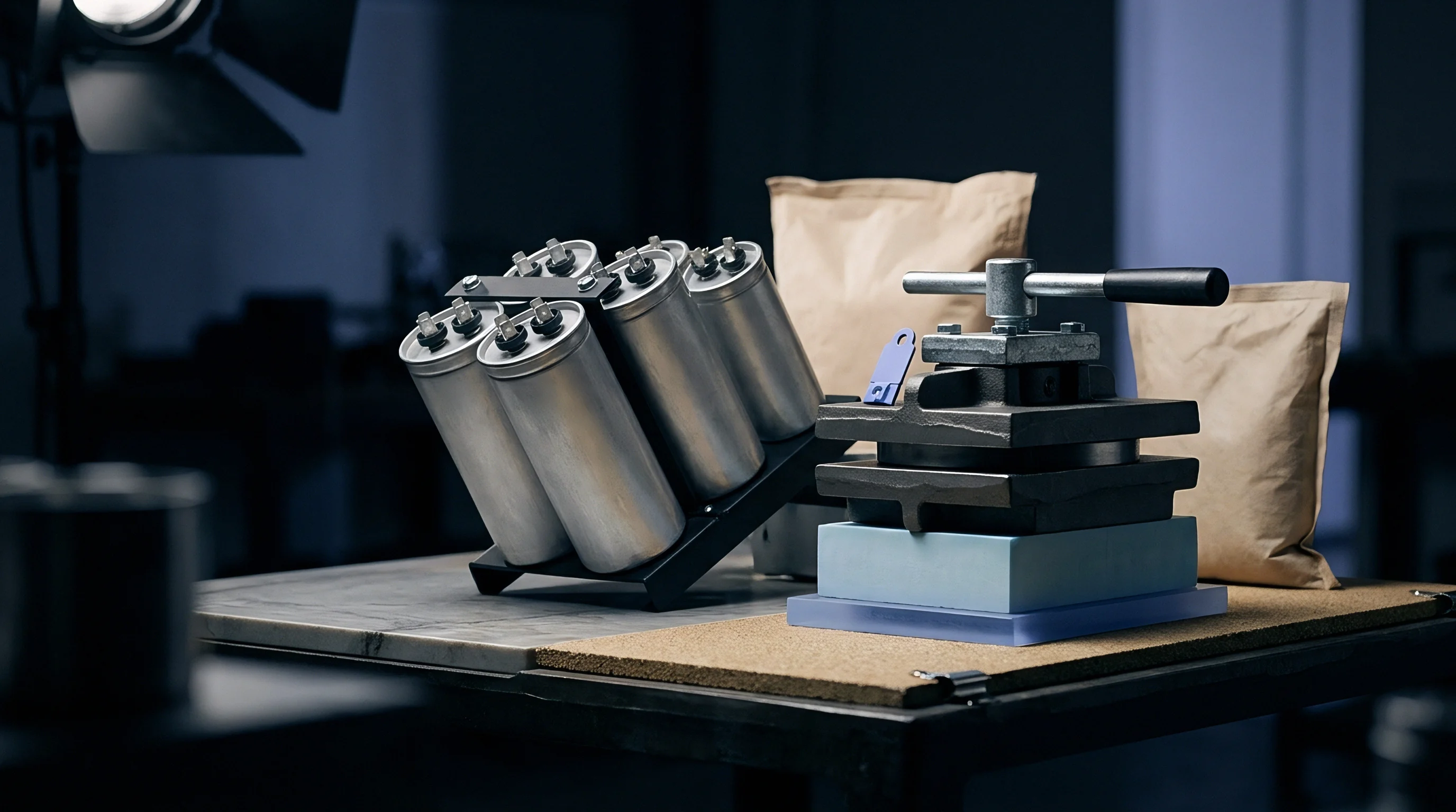
Custom extrusion dies, injection molds, and automated welding fixtures require heavy upfront capital before production starts. Standardizing around high-volume off-the-shelf cylindrical or prismatic cells avoids cell-level tooling NRE, limiting capital expenditure to pack assembly fixtures, busbar stamping dies, and plastic module trays. Injection molds for custom module end frames and cell holders cost between fifty thousand and two hundred thousand dollars per set, requiring substantial production volume to amortize conversion costs.
Custom pouch dimensions require dedicated aluminum laminate tooling, vacuum sealing nests, and formation charging trays at the cell factory. Cell manufacturers pass these costs to buyers as NRE fees ranging from two hundred thousand to over one million dollars. If annual production stays below ten thousand packs, amortized NRE strongly favors off-the-shelf cell formats despite the volumetric compromises.
Tooling amortization costs for custom prismatic extruded aluminum module trays alter the landed pack price balance once annual volume crosses twenty thousand units.
Compliance Ownership and Warranty Boundaries
Contractual terms define whether the cell supplier or the pack builder carries liability for safety certification. Standalone loose cells are qualified under component standards like UL 1642 and IEC 62133, proving basic electrochemical and mechanical safety. Assembling those cells into a finished pack requires full system-level re-certification under UN 38.3 transport regulations, UN ECE R100 electric vehicle standards, and stationary storage rules under UL 1973 or UL 9540.
Compliance ownership dictates where warranty liability falls. When a pack suffers early capacity fade or thermal failure, disputes quickly arise over whether cell chemistry or poor thermal management caused the issue. Integrating clear technical data boundaries into supply contracts protects both parties.
Specifications must explicitly define operating temperature ranges, maximum continuous charge C-rates, cell compression limits, and voltage windows. Exceeding agreed parameters shifts warranty liability from the cell vendor to the pack integrator.
- UN 38.3 Transport Test Dossier Complete test documentation confirming pack survival under altitude simulation, thermal cycling, shock, vibration, external short circuit, impact, and forced discharge.
- UL 1973 Safety Compliance File Certified laboratory test records covering electrical risk protection, mechanical stress testing, environmental exposure, and single-cell thermal runaway propagation resistance.
- Cell Specification Boundary Annex Signed contractual addendum defining precise upper limits for continuous charge current, operating temperature envelopes, and mechanical end-of-life swell allowance.
- Material Traceability and Certificate of Analysis Batch-level chemical purity and dimensional inspection records linked to unique cell matrix barcodes for full production traceability.
- Quality Agreement and Inspection Protocol Formally defined acceptance quality limit thresholds, incoming lot sampling plans, and micro-ohm busbar weld defect rejection criteria.
Tooling investments, assembly line cycle times, and compliance responsibilities determine whether a cell format produces sustainable margins. Settling compliance file ownership early prevents disputed engineering change orders when system-level testing begins.